

JBL TLXPS-10 Service manual
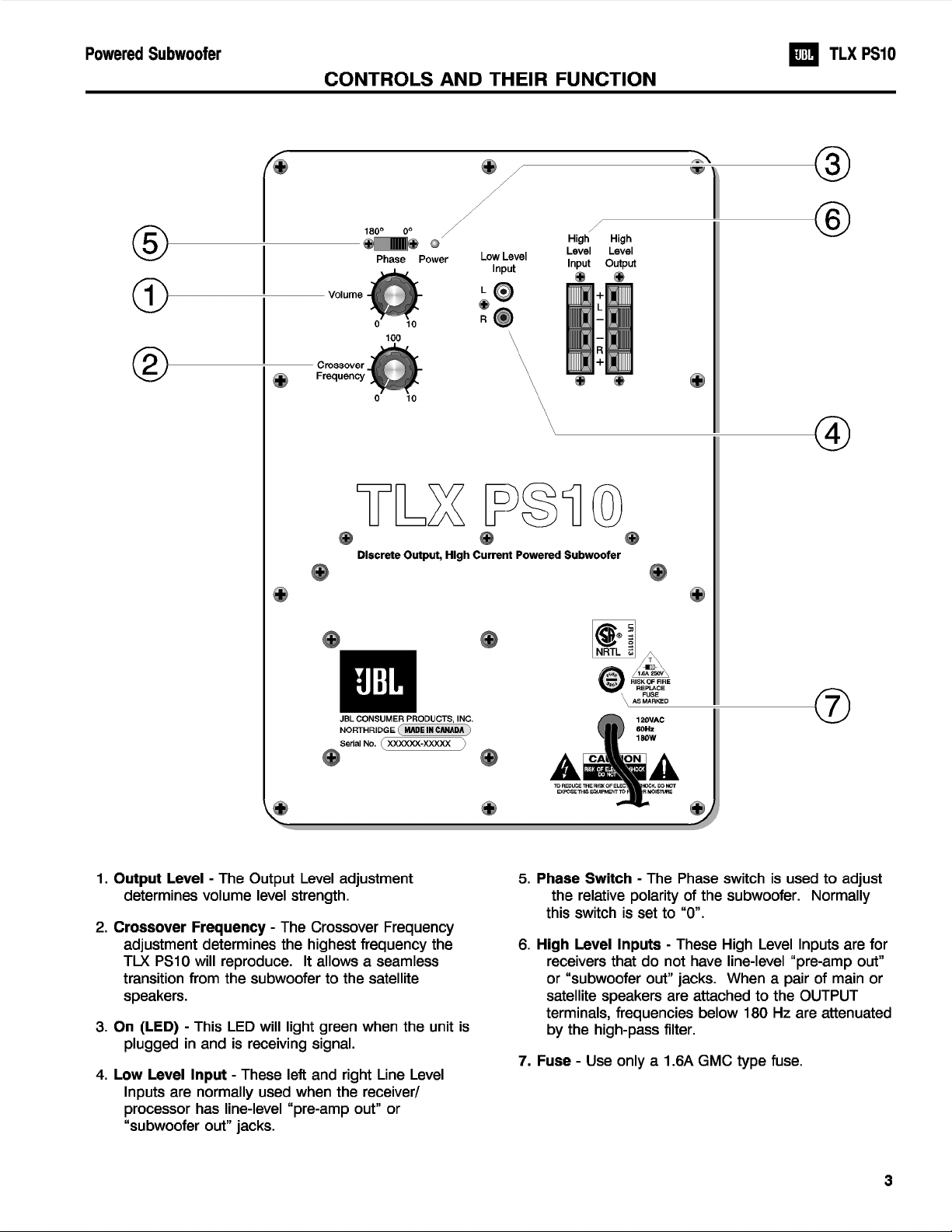
SERVICE MANUAL
TLX PS10
Discrete Output, High Current
10" Powered Subwoofer
JBL Consumer Products Inc.
250 Crossways Park Drive
Woodbury, N.Y. 11797
8500 Balboa Blvd.
Northridge, CA 91329
A Harman International Company
1112-TLXPS10 Rev A

Powered Subwoofer TLX PS10
TABLE OF CONTENTS
Specifications ..................................................................1
Warranty ..........................................................................2
Safety Symbols ...............................................................2
Controls and Their Functions.........................................3
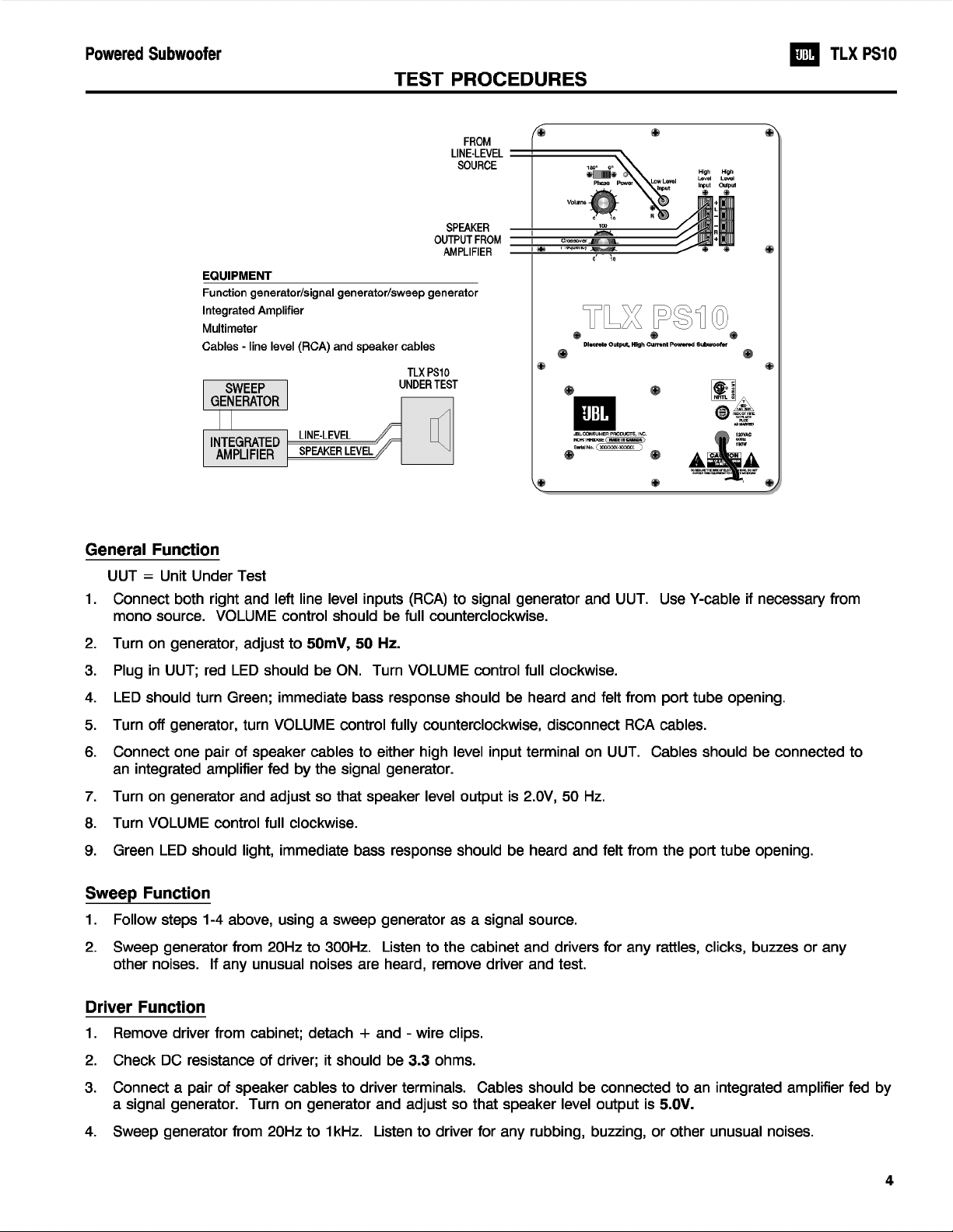
Test Procedure................................................................4
Trouble Shooting Before Opening.................................5
Removing the Amplifier ..................................................5
Trouble Shooting After Removal ....................................5
Components Requiring Exact Replacement .................6
SPECIFICATIONS
Amplifier Power RMS ...........100Watts
Drivers ................10"with high-polymer-laminated cones
Inputs.................Line level and Speaker Level
Outputs*................High level with High-Pass filter at 180Hz
Crossover Frequency ...........50-150Hz
(continuosly variable)
Frequency Response ...........30Hz to (50-150Hz)
(-6dB)
Block Diagram ................................................................7
Amplifier Exploded View.................................................8
Cabinet Exploded View ..................................................9
Parts Lists......................................................................10
Packaging and Shipping ..............................................12
Integrated Circuit Diagrams .........................................13
Printed Circuit Boards .................................................14
Schematic Diagrams ...................................................16
External Dimensions (Inches)
Height ................17"
Width .................13"
Depth.................163/4"
Weight ................36lbs
Shipping Weight .............42lbs
External Dimensions (mm)
Height ................432mm
Width .................330mm
Depth.................426mm
Weight ................16.4 kg
Shipping Weight .............19kg
* High-Level (speaker) outputs are active only if high-level input are used.
Occasional refinements may be made to existing products without notice, but will always meet
or exceed original specifications unless otherwise stated.
1
Powered Subwoofer TLX PS10
WARRANTY
This amplifier is warranted against defects in material
and workmanship for a period of 90 days from date of
shipment, when installed in accordance with the owner’s
manual in a clean, dry, interior home environment. THIS
AMPLIFIER IS NOT SUITABLE FOR OPERATION OUTSIDE
OR IN HARSH ENVIRONMENTS. During the warranty
period, the manufacturer will, at its option, either repair of
replace products which prove to be defective.
For warranty service or repair, this product must be
properly packed and returned to a service facility
designated by the manufacturer. Buyer shall prepay
shipping charges to the designated facility and the
manufacturer shall pay shipping charges to return the
product to buyer. However, Buyer shall pay all shipping
charges, duties and taxes for products returned to the
manufacturer from another country.
The manufacturer does not warrant that the operation
of the product will be uninterrupted or error-free. The
Buyer must determine the suitability of the product for his
or her purposes.
LIMITATION OF WARRANTY
The foregoing warranty shall not apply to defects
resulting from improper or inadequate maintenance by
Buyer, Buyer-supplied interfacing, unauthorized
modification or misuse, operation outside of the
environment specifications for the product including
inadequate ventilation, or improper site preparation,
installation, or maintenance.
NO OTHER WARRANTY IS EXPRESSED OR IMPLIED.
THE MANUFACTURER SPECIFICALLY DISCLAIMS THE
IMPLIED WARRANTIES OF MERCHANTABILITY AND
FITNESS FOR A PARTICULAR PURPOSE.
EXCLUSIVE REMEDIES
THE REMEDIES PROVIDED HEREIN ARE BUYER’S
SOLE AND EXCLUSIVE REMEDIES. THE
MANUFACTURER SHALL NOT BE LIABLE FOR ANY
DIRECT, INDIRECT, SPECIAL, INCIDENTAL, OR
CONSEQUENTIAL DAMAGES, WHETHER BASED ON
CONTRACT, TORT, OR ANY OTHER LEGAL THEORY.
SAFETY SYMBOLS
The following symbols are used throughout this manual
and in the product. Familiarize yourself with each of the
symbols and its meaning before servicing this amplifier.
Instruction manual symbol. The product will
be marked with this symbol when it is necessary
for the user to refer to the instruction manual in
order to protect the unit against damage.
Indicates dangerous voltages are present. Be
extremely careful.
The CAUTION sign denotes a hazard. It calls
attention to a procedure which, if
not correctly performed or adhered
to, could result in damage to or
destruction of the amplifier. Do not proceed beyond a
CAUTION sign until the indicated conditions are fully
understood and met.
The WARNING sign denotes a
hazard. It calls attention to a
procedure which, if not correctly
performed or adhered to could
result in injury or loss of life. Do not proceed beyond a
WARNING sign until the indicated conditions are fully
understood and met.
GENERAL SAFETY CONSIDERATIONS
THIS UNIT DOES NOT HAVE A POWER SWITCH;
HAZARDOUS VOLTAGES ARE PRESENT WITHIN THE
UNIT WHENEVER IT IS PLUGGED IN. This still applies
when the over-temperature thermostat opens, as it may
automatically reset at any time.
There are voltages and hot components at many points
in the amplifier which can, if contacted, cause serious
injury. Be extremely careful. Any adjustments or service
procedures that require operation of the amplifier out of its
enclosure should be performed only by trained service
personnel.
2
Powered Subwoofer TLX PS10
BEFORE THIS AMPLIFIER IS PLUGGED IN, make sure its rated voltage corresponds to the voltage of the AC power
source to be employed. Failure to use the correct voltage could cause damage to the amplifier when the AC power cable is
plugged in. Do not exceed the rated voltage by more than 10%; operation below 90% will degrade performance or cause the
unit to shut off.
1. TROUBLE SHOOTING BEFORE OPENING
Check connections, control settings, driver and other
possible external problems. If there is Output, determine if
all controls and Inputs function properly. Rotate Pots over
full range while applying lateral and vertical oscillating
forces to locate possible intermittent function. High Level
Inputs should be tested individually both differentially
(signal from "-" to "+" with normal output) and in common
mode (signal from low level ground to both "+" and "-"
shorted together, giving virtually no output). While passing
a signal, corner drop the enclosure a few inches to expose
possible intermittent problems. Check woofer for rubbing
of voice coil or tears in cone or surround. Check cabinet
for loose extraneous articles which may have been pushed
into front port.
If line core, its strain relief, or the AC switch are
replaced, it is necessary to seal them completely to panel
with an approved conformal coating to prevent air
"whistling" through any openings from woofer pressure.
To reduce the risk or electric shock and/or
fire, replace items as marked on schematic
with the safety marking only with the exact
replacements listed in the safety component
list, section 5. If exact replacements are not available,
order them from the factory or an authorized service
center.
2. REMOVING THE AMPLIFIER.
There are voltages and hot components at many points
in the amplifier which can, if contacted, cause personal
injury. Be extremely careful. Any adjustments or service
procedures that require operation of the amplifier out of its
enclosure should be performed only by trained service
personnel. Refer to PCB drawings for locations of hazards
and familiarize yourself with their locations before starting.
3. TROUBLE SHOOTING AFTER REMOVAL
Verify AC plug is disconnected See WARNINGS in
section 2.
To prevent loose hardware from reducing safety
spacings, it is essential that all hardware be replaced in the
same manner as it was removed, with lock washers under
all nuts, proper torque on screws and thread locking sealer
on the transformer nuts.
A.) Check fuse F1. If blown visually check transformer
for discoloration, and large capacitors (C36, C37) for
bulges or venting. Check for shorts in Q3-Q7 with
an Ohmmeter, (see schematic).
B. With ohmmeter, verify contacts of thermostat are
closed, voice coil of woofer is 3.3 ohms and
windings of transformer are continuous.
C. Examine board and wiring for obvious damage,
broken or poorly soldered connections, or
discoloration.
D. Repair or replace items identified above.
Procedures for replacing power transistors and
removing PCB are as follows:
Use low power, grounded temperature regulated iron
with small tip such as Weller PTA7 and ESD control.
Use SN63/37 solder 0.032" diameter with "no clean"
flux core, Alpha Metals P2 or equal.
I) Replacing power transistors:
near body of transistor. Remove screw and
discard device (keep hardware and insulator).
Holding each lead in turn with needle nose
Clip all 3 leads
5
 Loading...