

Page 1

SYNTHESIS
SDEC-1000/2500
INSTALLATION
GUIDE
Page 2

Page 3

TABLE
OF
CONTENTS
SECTION ___________________________________________________________PAGE
1.0 _________________________________________________________PRECAUTIONS
5.5 Important Safeguards for Audio Products _________________________________________7–10
2.0_____________________________________________INTRODUCTION TO THE SDEC
2.0 Introduction __________________________________________________________________________11
The Concept __________________________________________________________________________11
2.1 SDEC-1000 and SDEC-2500 Rear Panels ____________________________________________________12
2.2 What the SDEC does_________________________________________________________________13–17
Driver EQ ____________________________________________________________________________13
Driver Time Correction __________________________________________________________________14
Channel-to-Channel Distance Correction (Auto-Time Correction)__________________________________15
Crossovers ___________________________________________________________________________15
Screen Correction______________________________________________________________________16
Modes_______________________________________________________________________________16
Room Correction EQ_________________________________________________________________16–17
3.0 __________________________________________________INSTALLING THE SDEC
3.1 Location, Location, Location . . .___________________________________________________________18
3.2 A Note On Wiring ______________________________________________________________________19
3.3 Wiring Connections to the SDEC________________________________________________________20–22
Case I – Replacing an analog equalizer in an existing Synthesis system _________________________20–21
Case II – Installing an SDEC as part of a new Synthesis system installation_______________________21–22
Power the system up for the first time ______________________________________________________22
4.0_______________________________THE DIGITAL ACOUSTIC CALIBRATION SYSTEM
4.1 Operational Overview ________________________________________________________________23–27
Stimulus _____________________________________________________________________________23
Data Acquisition ____________________________________________________________________23–24
Data Post-Processing___________________________________________________________________24
Display Data __________________________________________________________________________24
Make Corrections ______________________________________________________________________25
Target Curves ______________________________________________________________________25
Ideal Low-Frequency Response __________________________________________________25–26
Ideal High-Frequency Response__________________________________________________26–27
4.2 DACS4 Connections and Use __________________________________________________________28–32
Things To Consider When Selecting A Location For DACS4 ______________________________________28
Hookup ______________________________________________________________________________29
AC/Power Connections _______________________________________________________________29
Audio Connections __________________________________________________________________30
Other Connections __________________________________________________________________30
Microphone Connection and Placement _______________________________________________30–32
3
Page 4

4
Room Placement ________________________________________________________________30
How is the Room Used?________________________________________________________31
Microphone #1 _______________________________________________________________31
Now Place the Remaining Microphones _________________________________________31–32
4.3 Power Up Synthesis and DACS4___________________________________________________________33
4.4 Preliminary Surround Processor Settings____________________________________________________34
I. Global Settings ______________________________________________________________________34
II. Mode Specific Settings________________________________________________________________34
4.5 DACS4 Operation ___________________________________________________________________35–40
Notational Conventions__________________________________________________________________35
About Online Help___________________________________________________________________35
[F-1] Help ______________________________________________________________________35
Starting DACS4________________________________________________________________________35
Initial DACS4 Screen_________________________________________________________________36
Enter Customer Information___________________________________________________________37
Synthesis Model____________________________________________________________________38
Select a Surround Processor __________________________________________________________38
Center Screen Compensation __________________________________________________________39
Left/Right Compensation _____________________________________________________________39
Confirm DACS4 Connections __________________________________________________________40
4.6 DACS4 Main Screen _________________________________________________________________41–45
Response Graph _______________________________________________________________________42
Filters at a Glance ______________________________________________________________________42
Individual Filter Control__________________________________________________________________43
Channel and Mode Selection/Status ________________________________________________________43
Overlay Previously Tested Channels ________________________________________________________44
Online Help___________________________________________________________________________44
Special Function Keys________________________________________________________________44–45
4.7 Calibration Walk-Through _____________________________________________________________46–56
Auto-Time Correction ___________________________________________________________________47
Cinema, Subwoofer Calibration_________________________________________________________48–50
Setting the Level ____________________________________________________________________49
Auto-Equalization ___________________________________________________________________50
Cinema, Left – Center – Right Calibration_________________________________________________48–50
Setting the Level____________________________________________________________________51
Run Auto-EQ_______________________________________________________________________52
Left and Right Ambient Calibration______________________________________________________52–53
Setting The Level ___________________________________________________________________53
Music Mode Calibration _________________________________________________________________53
TABLE
OF
CONTENTS
SECTION ___________________________________________________________PAGE
Page 5

TABLE
OF
CONTENTS
SECTION ___________________________________________________________PAGE
Quitting DACS4________________________________________________________________________54
After A Complete Calibration __________________________________________________________54
Quitting When Some Channels Are Not Accepted___________________________________________54
SDEC Maintenance _____________________________________________________________________54
Using the Loader Utility ______________________________________________________________54
Troubleshooting ____________________________________________________________________55–56
Correcting Hum Problems ____________________________________________________________55
Why Does It Hum In The First Place?_________________________________________________55
What You Can Do During Installation _________________________________________________55
Video Devices___________________________________________________________________56
5.0 _______________________________________________________SPECIFICATIONS
5.0 Specifications _________________________________________________________________________57
6.0 ___________________________________________INTERCONNECTION DIAGRAMS
Synthesis One Interconnection Diagram _____________________________________________________58–59
Synthesis Two and Three Interconnection Diagram ____________________________________________60–61
7.0 ____________________________________________CONTROL WIRING DIAGRAMS
Synthesis One Control Wiring Diagram______________________________________________________62–63
Synthesis Two and Three Control Wiring Diagram _____________________________________________64–65
8.0__________________________________________SYNTHESIS LIMITED WARRANTY
6.0 Synthesis Limited Warranty ______________________________________________________________66
JBL Synthesis SDEC-1000/2500
Installation Guide
©1998 Harman Digital Systems Group
“Dolby” and “Pro Logic” are trademarks of Dolby Laboratories.
Confidential Unpublished Works. ©1992–1997
Dolby Laboratories, Inc. All Rights Reserved
THX is a registered trademark of Lucasfilm, Ltd.
JBL and Synthesis are registered trademarks of JBL Incorporated.
All Rights Reserved
Design and digital production by Harman Digital Systems Group
Design and Production Center, Woodbury, New York
JBL Consumer Products
250 Crossways Park Drive, Woodbury, NY 11797
8500 Balboa Boulevard, Northridge, CA 91329
800-336-4JBL
Printed on Recycled Paper
Part Number: 1113-SDECInstal
5
Page 6

TABLE
OF
Figures
Figure 1: Raw Driver Response/Corrected Driver Response _________________________________________13
Figure 2: System With & Without Driver Time Correction___________________________________________14
Figure 3: Effect of Auto-Time Correction________________________________________________________15
Figure 4: Effect of Screen Correction EQ ________________________________________________________16
Figure 5: Effect of Room EQ _________________________________________________________________17
Figure 6: System Response In 5 Locations ______________________________________________________26
Figure 7: Synthesis 1 Main Target Curve, Below 1kHz______________________________________________28
Figure 8: Complete Synthesis 1 Target Curve ____________________________________________________29
Figure 9: DACS4 Connection to Synthesis_______________________________________________________31
Figure 10: Microphone Placement: Large Listening Area ____________________________________________33
Figure 11: DACS4 Opening Screen _____________________________________________________________37
Figure 12: Customer Information Window _______________________________________________________38
Figure 13: Customer Information Window: Select A Synthesis Model___________________________________39
Figure 14: Select A Surround Processor _________________________________________________________39
Figure 15: Identify Screen Type, Center Channel ___________________________________________________40
Figure 16: Identify Screen Type, Left & Right Front_________________________________________________40
Figure 17: DACS4 On Screen Wiring Diagram_____________________________________________________41
Figure 18: DACS4 Main Calibration Screen _______________________________________________________42
Figure 19: Response Graph Window ____________________________________________________________43
Figure 20: Filter Setting and Control Field ________________________________________________________43
Figure 21: Filter Control Field _________________________________________________________________44
Figure 22: Direct Channel and Mode Access ______________________________________________________44
Figure 23: Channel Display Control Field_________________________________________________________45
Figure 24: Continuously Updated Online Help _____________________________________________________45
Figure 25: Function Keys and Status Line ________________________________________________________45
Figure 26: Channel Gain and Delay Information ___________________________________________________46
Figure 27: Fresh Install, First Screen____________________________________________________________47
Figure 28: Auto-Time Correction Dialog Box ______________________________________________________48
Figure 29: Ready For Subwoofer Level Test ______________________________________________________49
Figure 30: Setting Level______________________________________________________________________50
Figure 31: Without Smoothing Filter ____________________________________________________________50
Figure 32: Results of Auto-EQ _________________________________________________________________51
Figure 33: Left Cinema Level Set_______________________________________________________________52
Figure 34: Auto-EQ _________________________________________________________________________53
Figure 35: Ambient Target____________________________________________________________________54
6
Page 7
The lightning flash with arrowhead
symbol, within an equilateral triangle, is intended to alert the user to
the presence of uninsulated ”dan-
gerous voltage” within the product's
enclosure that may be of sufficient magnitude to
constitute a risk of electric shock to persons.
The exclamation point within an
equilateral triangle is intended to
alert the user to the presence of
important operating and maintenance (servicing) instructions in
the literature accompanying the unit..
CAUTION
RISK OF ELECTRIC SHOCK
DO NOT OPEN
CAUTION: TO REDUCE THE RISK OF ELECTRIC SHOCK, DO NOT REMOVE COVER (OR BACK). NO
USER-SERVICEABLE PARTS INSIDE. REFER SERVICING TO QUALIFIED SERVICE PERSONAL.
WARNING: TO REDUCE THE RISK OF FIRE OR ELECTRIC SHOCK, DO NOT EXPOSE THIS UNIT
TO RAIN OR MOISTURE.
CAUTION: TO PREVENT ELECTRIC SHOCK, DO NOT USE THIS (POLARIZED) PLUG WITH AN EXTENSION CORD RECEPTACLE OR OTHER OUTLET UNLESS THE BLADES CAN BE FULLY INSERTED TO PREVENT
BLADE EXPOSURE.
ATTENTION: POUR PREVENIR LES CHOCS ELECTRIQUES NE PAS
UTILISER AVEC UN PROLONGATEUR. UNE PRISE DE COURANT OU UNE
AUTRE SORTIE DE COURANT SAUF SI LES LAMES PEUVENT ETRE
INSEREES A FOND SANS EN LAISSER AUCUNE PARTIE A DECOUVERT.
1.1
IMPORTANT SAFEGUARDS
7
1.0
PRECAUTIONS
1.1 Important Safeguards
For Audio Products
PLEASE READ CAREFULLY ALL THE
FOLLOWING IMPORTANT SAFEGUARDS
THAT ARE APPLICABLE TO YOUR EQUIPMENT
1. Read Instructions – All the safety and operating
instructions should be read before the product
is operated.
2. Retain Instructions – The safety and operating
instructions should be retained for future reference.
3. Heed Warnings – All warnings on the product
and in the operating instructions should be
adhered to.
4. Follow Instructions – All operating and use
instructions should be followed.
5. Water and Moisture – The product should not
be used near water – for example, near a bathtub,
washbowl, kitchen sink, laundry tub, in a wet basement, or near a swimming pool, and the like.
6. Carts and Stands – The product should be
used only if a cart or stand is recommended by
the manufacturer.
6a. A product and cart combination should be moved
with care. Quick stops, excessive force, and
uneven surfaces may cause the product and cart
combination to overturn.
7. Wall or Ceiling Mounting – The product
should be mounted on a wall or ceiling only when
and as recommended by the manufacturer.
8. Ventilation – The product should be situated
so that its location or position does not interfere
with its proper ventilation. For example, the product should not be situated on a bed, sofa, rug, or
similar surface that may block the ventilation
openings; or placed in a built-in installation, such
as a bookcase or cabinet, that may impede the flow
of air through the ventilation openings.
9. Heat – The product should be situated away
from heat sources such as radiators, heat registers,
stoves, or other products that produce heat. If
placed near an amplifier, check with the
manufacturer for applicability.
10. Power Sources – The product should be
connected to a power supply only of the type
described in the operating instructions or as
marked on the product.
11. Grounding or Polarization – Precautions
should be taken so that the grounding or
polarization means of a product is not defeated.
12. Power-Cord Protection – Power-supply cords
should be routed so that they are not likely to be
walked on or pinched by items placed upon or
against them, paying particular attention to cords
at plugs, convenience receptacles, and the point
where they exit from the product.
13. Cleaning – The product should be cleaned only
as recommended by the manufacturer.
14. Power Lines – An outdoor antenna should be
located away from power lines.
Page 8
8
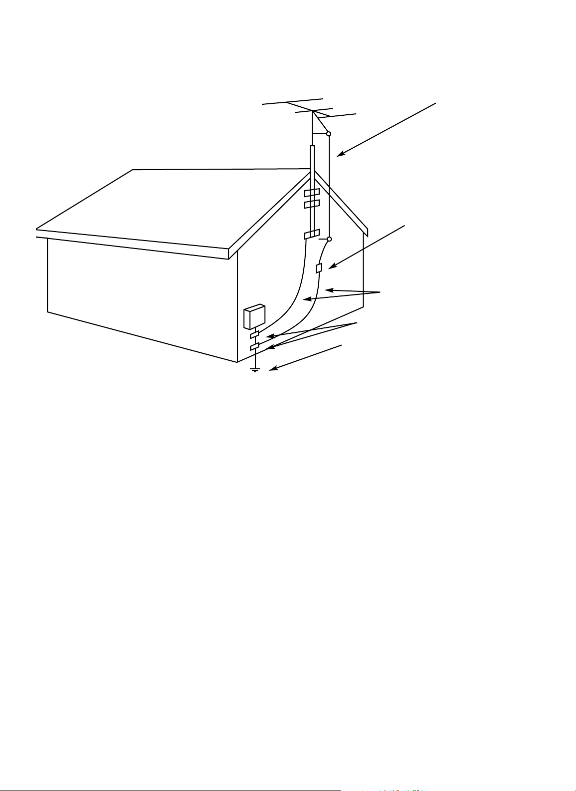
ANTENNA
LEAD-IN
WIRE
ANTENNA
DISCHARGE UNIT
(NEC SECTION 810-20)
GROUNDING CONDUCTORS
(NEC SECTION 810-21)
GROUND CLAMPS
POWER SERVICE GROUNDING
ELECTRODE SYSTEM
(NEC ART 250, PART H)
Example of Antenna Grounding
as per National Electrical Code
1.1
IMPORTANT SAFEGUARDS
15. Nonuse Periods – The power cord of the product should be unplugged from the outlet when left
unused for a long period of time.
16. Object and Liquid Entry – Care should be taken
so that the objects do not fall and liquids are not
spilled into the enclosure through the openings.
17. Outdoor Antenna Grounding – If an outside
antenna is connected to the receiver, be sure the
antenna system is grounded so as to provide some
protection against voltage surges and built-up
static charges. Article 810 of the National Electrical
Code, ANSI/NFPA 70, provides information with
regard to proper grounding of the mast and
supporting structure, grounding of the lead-in
wire to an antenna-discharge unit, size of grounding conductors, location of antenna-discharge
unit, connection to grounding electrodes, and
requirements for the grounding electrode (see
above figure).
18. Damage Requiring Service – The
product should be serviced by qualified service
personnel when:
a. The power supply or the plug has been
damaged; or
b. Objects have fallen on, or liquid has been
spilled into, the product; or
c. The product has been exposed to rain; or
d. The product does not appear to operate
normally or exhibits a marked change in
performance; or
e. The product has been dropped, or the
enclosure damaged.
19. Servicing – The user should not attempt to service the product beyond what is described in the
operating instructions. All other servicing should
be referred to qualified service personnel.
Note To CATV System Installer:
This reminder is provided to call the CATV system
installer’s attention to Article 820-22 of the NEC
that provides guidelines for proper grounding and,
in particular, specifies that the cable ground shall be
connected to the grounding system of the building,
as close to the point of cable entry as practical.
Page 9
Français
Instructions de Sûreté Importantes
Gardex ces instructions pour réference future.
Observez toutes les instructions et tous les avertissements marqués sur l’appareil.
Branchez uniguements sur un réseau de tension indiquée. Consultez le manuel
d’instruction du fabriquant pour les spécifications de courant. N’oubliez pas que
différentes tensions peuvent nécessiter l’utilisation de cables et/ou de fiches
deconnexion différents.
N’installez pas l’appareil en un compartiment non-aéré ou directement au-dessus
d’équipements générateurs de chaleur, tels qu’amplificateurs de courants, etc. Ne
dépassez pas la température ambiante maximale de fonctionnement indiquée
dans les spécifications du produit.
Des fentes et ouvertures sont prévues dans le boîtier pour l’aération; Pour assurer
le bon fonctionnement et pour prévenir l’échauffement, ces ouvertures ne doivent
pas être couvertes ou bloquées. N’insérez pas d’objets dans les fentes d’aération.
Empêchez tout liquide de se répandre sur l’appareil.
Ce produit est muni d’une fiche à trois fils pour la mise à terreee. Ceci est une
mesure de sécurité et ne doit pas être contrariée.
Ne connectez jamais d’amplificateurs audio directement aux connecteurs de
l’appareil.
Pour empêcher les chocs électriques et le danger d’incendie, évitez d’exposer
l’appareil à la pluie ou à l’humidité, et ne le mettez pas en marche en un endroit
où il serait exposé aux éclaboussures d’eau.
N’essayez pas de faire fonctionner l’appareil s’il est tombé à terre, a été endommangé, exposé à un liquide, ou si vous observez des différences nettes dans son
fonctionnement, indiquant la nécessité de réparations.
Cet appareil ne doit être ouvert que par un personnel de service qualifié. En enlevant les couvercles vous vous exposez àdes tensions électriques dangereuses.
Ce triangle, sur votre appaeil vous avertit de la présence de tension dangereuse, non-isolée à l’intérieur du boîtier…une tension
suffisante pour représenter un danger d’electrocution.
Ce triangle sur sur votre appareil vous invite de suivre d’importantes instructions d’utillisation et d’entretien dans la documentation livrée avec le produit.
Español
Instrucciones importantes de sequiridad
Guarde esta instrucciones para uso posterior.
Utilice siempre el voltaje correcto. Diríjase a las instrucciones de operación del
fabricante para obtener las especificaciones de potencia. Esté al tanto de que
voltajes de operación distintos requieren el uso de cable y/o enchufes distintos.
No instale esta unidad en un estante sin vntilación, ni tampoco directamente
encima de equipose que generen calor tales como amplificadores de potencia.
Fíjese en las temperaturas ambientales máximas de operación que se mencionan
en las especificaciones del producto.
Las aperturas y ranuras del chasis sirven para proveer la ventilación necesaria
para operar la unidad con sequridad y para prevenir sobrecalentamiento, y por lo
tanto no pueden ser obstruidas o cubiertas. No introcuzca objetos de ningún tip
a través de las ranuras de ventilación, y nunca deje caer ningún líquido sobre
la unidad.
Este producto está equipado con un enchufe de 3 clavijas con conexión a ierra.
Este es un elemento de seguridad que no debe ser eliminado.
Nunca conecte ningùn tipo de salida de amplificadores de sonido directamente a
los conectores de la unidad.
Para prevenir descargas eléctricas o incendios, mantenga la unidad alejada de la
lluvia, humedad o cualquier lugar en el que pueda entrar en contacto con ague.
No trate de hacer funcionar la unidad si se ha caído, está dañada, ha entrado en
contacto con lítuidos, o si nota cualquir cambio brusco en su funcionamiento
que indique la necesidad de hacerle un servicio de mantenimiento.
Esta unidad deberá ser abierta únicamente por personal calificado. Si usted quita
las coberturas se expondrá a voltajes peligrosos.
Este triángulo que apaece en su componente le advierte sobre
la existencia dentro del chasis de voltajes peligrosos sin
aislantes…voltajes que son lo suficientemente grandes como
para causar electrocución.
Este triángulo que aparece en su componente lo alerta sobre las
instrucciones de operación y mantenimiento importantes que
están en los materiales de lectura que se incluyen.
Italiano
Importanti norme di sicurezza
Conservare le presenti norme per l’utilizzo futuro.
Osservare tutte le istruzioni e le avvertenze apposte sull’unita.
Utilizzare esclusivamente con la tensione di rete corretta. Consultare le istruzioni
operative fornite dal fabbricante per i dati riguardanti la tensione e l’assorbimento
di corrente. Potrebbe essere necessario l’uso di cavi di rete e/o di spine diverse a
seconda della tensione utilizzata.
Non installare l’unità in uno scaffale privo di ventilazione oppure direttamente
sopra una fonte di calore, come, ad esempio, un amplificatore. Non superare la
temperatura ambientale massima di funzionamento riportata nei dati tecnici del
prodotto.
Le fessure e le altre aperture nella scatola servono alla ventilazione. Per un funzionamento affidabile, e per evitare un eventuale surriscaldamento, queste aperture non vanno ostruite o coperte in nessun modo. Evitare in tutti i casi di inserire
oggetti di qualsiasi genere attraverso le fessure di ventilazione. Non versare mai
del liquido di nessun tipo sull’unità.
Questo pordotto viene fornito con una spina a 3 fili con massa. Tale dispositivo di
sicurezza non va leiminato.
Evitare sempre di collegare le uscite dell’amplificatore auio direttamente ai connettori dell’unità.
Per prevenire il pericolo di folgorazione e di incendio non esporre l’unità alla
pioggia o ad un’umidtà eccessiva; evitare di adoperare l’unità dove potrebbe
entrare in contatto con acqua.
Evitare di adoperare l’unità se la stessa è stata urtata violentemente, se ha subito
un danno, se è stata esposta ad un liquido o in caso di un evidente cambiamento
dell prestazioni che indichi la necessità di un intervento di assistenza tecnica.
Ogni intervnto sull’unità va esqguito esclusivamente da personale qualificato. La
rimozione della copertura comporta l’esposizione al pericolo di folgorazione.
ll present triangolo impresso sul componente avverte della
presenza di tensioni pericolose non isolate all’interno della
copertura…tali tensioni rappresentano un pericolo di folgorazione
ll presente triangolo imprsso sul componente avverte l’utente della
presenza nella documentazione allegata di importanti istruzioni
relative al funzionament ed alla manutenzione.
Deutsch
Wichtige Sicherheitsanweisungen
Heben Sie sich diese Sicherheitsanweisungen auch für später auf.
Befolgen Sie alle auf der Vorrichtung stehenden Anweisungen und Warnungen.
Immer nur mit der richtigen Spannung verwenden! Die Gebrauchsanweisungen
des Herstellers informieren Sie über die elektrischen Anforderungen. Vergessen
Sie nicht daß bei vershiedenen Betrievsspannungen ggf. auch verschiedene
Leitungskabel und/oder Verbindungsstacker zu verwenden sind.
Stellen Sie die Vorrightung nicht in ein unbelüftetes Getell oder unmittelbar
über wärmeerzeugende Geräte wie z.B. Tonverstärker. Halten Sie die in den
Produktspezifikationen angegebene maximale Umgebungstemperatur bei
Betrieb ein.
Schlitze und Öffnungen im GehUause dienen der Belüfung; um verläßlichen
Betrieb sicherzustellen und Überheizen zu vermeiden dürfen diese Öffnungen
nich verstopft oder abgedeckt werden. Stecken Sie nie irgend einen Gegenstand
durch die Belüftungsschlitze. Vergießen Sie keine Flüssigkeiten auf den Apparat.
Dieses Produkt is mit einem 3-drahtigen Erdungsstecher ausgerüstet. Diese
Sicherheitsmaßnahme darf nicht unwirksam gemacht werden.
Schließen Sie nie Tonverstärker unmittelbar an einen Anschluß des
Apparates an.
Um elektrischen Schlag oder Feuer zu vermeiden, setaen Sie den Apparat
weder Regen noch Feuchtigkeit aus und betreiben Sie ihn nicht dort wo Wasser
eindringen könnte.
Versuchen Sie nicht den Apparat zu betreiben falls er fallen gelassen, beschädigt,
oder Flüssigkeiten ausgesetzt wurde, oder falls sich seine Arbeitsweise derart
ändert daß daraus ein Bedarf nach Raparatur zu schließen ist.
Dieser Apparat sollte nur von qualifizierten Fachleuten geöffnet
werden. Das Abnehmen von Abdeckungen setzt Sie
gefährlichen Spannungen aus.
Dieses Dreick auf ihrem Apparat warnt Sie voe nicht-isolierter,
gefährlicher Spannung im Gehäuse…stark genug um eine
Berührungsgefahr darzustellen.
Diese Dreick auf ihram Apparat bedeutet daß wichtige Betriebsund Wartungsanweisungen in der mitgelieferten Dokumentation
zu finden sind.
Page 10
Dansk
Vigtig information om sikkerhed
Gem denne vejledning til senere brug.
Følg all anvisninger og advaresler på apparatet.
Apparatet skal altid tilslttes den korrekte spænding. Der henvises til brugsanvis-
ningen, der indeholder specifikationer for strømforsyning. Der gøres opmærksom
på, at ved varierende driftsspændinger kan det blive nødvendigt at bruge andre
lednings- og/eller stiktyper.
Apparated må ikke monteres i et kabinet uden ventilation eller lige over andet
udstyr, der udvikler varme, f.eks. forstærkere. Den maksimale omgivelsestemperatur ved drift, der står opført i specifikationerne, skal overholdes.
Der er ventilationsåbninger i kainettet. For at sikre apparatets drift og hindre
overophidning må disse åbninger ikke blokeres elle tildækkes. Stik aldrig noget
ind igennem ventilationsåbningerne, og pas på aldrig at spilde nogen form for
væske på apparatet.
Dette apparat er forsynet med et stik med jordforbindelse. Denne sikkerhedsforanstaltning må aldrig omgås.
Udgangsstik fra audioforstærkere må aldrig sættes direkte i apparartet.
Apparatet må ikke udsættes for regn eller fugt og må ikke bruges i nærheden af
vand for at undgå risiko for elektrisk stød og brand.
Apparatet må aldrig bruges, hvis det er blevet stødt, beskadiget eller vadt, eller
hvis ændringer i ydelsen typer på, at det trænger til eftersyn.
Fette apparat må kun åbnes af fagfolk, Hvis dækslet tages af, udsættes man for
livsfarlig højspænding.
Denne mærkat på komponenten advarer om uisoleret, farlig
spænding i apparatet… høj nok til at give elektrisk stød.
Denne mærkat på komponenten advarer om vigtig driftsog
vedligeholdsinformation i den tilhørende litteratur.
Suomi
Tärkeitä varten
Säilytä nämä ohjeet tulevaa käyttoöä varten.
Seuraa kaikkia yksikköön merkittyjä ohjeita ja varoituksia.
Käytä aina oikeaa verkkojännitettä. Tehovaatimukset selviävät valmista-
jan käyttöohjjeista. Huomaa, että eri käyttöjännitteet saattavat vaatia
toisenlaisen verkkojohdon ja/tai- pistokkeen käytön.
Älä asenna yksikköä telineeseen jossa ei ole tuulet usta, tai välittömästi
lämpöä tuottavien laitteiden, esim. tehovahvistimien, yläpuolelle.
Ympäristön Iämpötila käytössä ei saa ylittää twotespesifikaation
maksimilämpötilaa.
Kotelo on varustettu tuuletusreiillä ja -aukiooa. Luotettavan toiminnan
varmistamisksi ja ylilämiseksi näitä aukkoja ei saa sulkea tai peittää.
Mitään esineitä ei saa työntää tuuletusaukkoihin. Mitään nestritä ei saa
kaataa yksikköön.
Tuote on varustettu 3-jjohtimisella maadoitetulla verkkipistokkeella.
Tämä on turvallisuustoiminne eikä sitä saa poistaa.
Älä kytke audiotehovahvistimen lähtöjä suoraan mihinkään yksikön
liittimeen.
Sähköiskun ja palovaaran välttämiseksi yksikkö ei saa olla sateessa tai
kosteassa, eikä sitä saa käyttää märässä ympäristössa.
Älä käytä yksikköä jos se on pudonnut, vaurioitunut, kostunut, tai jos
sen suorituskkyky on huomattavasti muuttunut, maikä vaatii huoltoa.
Yksikön saa avata vain laitteeseen perehtynyt huoltohenkilö. Kansien
poisto altistaa sinut vaarallisille jännittelille.
Tämä kolmio, joka esiintyy homponentissasi, varoittaa
siua eristämättömän vaarallisen jännitteen esiintymisestä
yksikön sisällä. Tämä jännite saattaa olla riittävä korkea
aiheuttamaan sähköiskuvaaran.
Tämä koimio, joka esiintyy komponentissasi, kertoo sinulle, että tässä tuotedokumentoinnissa esiintyy tärkeitä
käyttö-ja ylläpite-ohjeita.
Norsk
Viktig informasjon om sikkerhet
Ta vare pådenne veiledningen for senere bruk.
Følg alle anvisningene og advarslene som er angitt på apparatet.
Apparatet skal alltid anvendes med korrekt spenning.
Produktbeskrivelsen inneholder spesifikasjoner for strømkraav. Vær oppmerksom
på at det ved ulike driftsspenninger kan være nødvendig å bruke en annen
ledningog/eller støpseltype.
Apparatet skai ikke monteres i skap uten ventilasjon, eller direkte over varmeproduserende utstyr, som for eksempel kraftforsterkere. Den maksimale romtemperaturen som står oppgitt i produktbeskrivelsen, skal overholdes.
Apparatet er utstyrt med ventilasjonsåpninger. For at apparatet skal være pålitelig
i bruk og ikke overopphetes, må disse åpningene ikke blikkeres eller tildekkes.
Stikk aldri noe inn i ventilasjonsåpningene, og pass på at det aldri søles noen
form for væske på apparatet.
Dette apparatet er utstyrt med et jordet støpsel. Dette er en sikkerhetsforanstaltning som ikke må forandres.
Utgangsplugger fra audioforsterkere skai aldri koples direkte til apparatet.
Unngå brannfare og elektrisk støt ved å sørge for at apparatet ikke utsettes for
regn eller fuktighet og ikke anvendes i næheten an vann.
Apparatet skal ikke brukes hvis det har blitt utsatt for støt, er skadet eller blitt vått,
eller hvis endringer i ytelsen tyder på at det trenger service.
Dette apparatet skal kun åpnes av fagfolk. Hvis dekselet fjernes, utsettes man for
livsfarlig høyspenning.
Komponenten er merket med denne trekanten, som er en
advarsel om at det finnes uisolert, farlig spenning inne i kabinettet…høy nok til å utgjøre en fare for elektrisk støt.
Komponenten er merket med denne trkanten, som betyr at den
tilhørende litteraturen inneholder viktige opplysninger om drift
og vedikehold.
Svenska
Viktiga säkerhetsföreskrifter
Spara dess föreskrifter för framtida bruk.
Följ alla anvisningar och varningar som anges på engeten.
Använd alltid rätt nätspänning. Se tillverkarens bruksanvisningar för informa-
tion om effektkrav. Märkväl, att andra matningsspänningar eventuellt kräver att
en annan typs nätsladd och/eller kontakt anänds.
Installera inte enheten i ett oventilerat stativ, eller direkt ovanför utrustningar
som avger värme, t ex effektförstärkare. Se till att omgivningens temperatur vid
drift inte överskrider det angivna värdet i produktspecifikationen.
Behållaren är försedd med hål och öppningar för ventilering. För att garantera
tillförlitlig funktion och förhindra överhettning får dessa oppningar inte blockeras eller täckas. Inga föremål får skuffas in genom ventilationshålen. Inga
vätskor får spillas på enheten.
Produkten är försedd med en jordad 3-trådskontakt. Detta ä en säkerhetsfunktion som inte får tas ur bruk.
Anslut aldrig audioeffektförstärkarutgångar direkt till någon av enhetens
kontakter.
För att undvika elstöt eller brandfara får eenheten inte utsättas för reegn eller
fukt, eller användas på ställen där den blir våt.
Använd inte enheten om den far fallit i golbet, skadats, blivit våt, eller om dess
prestanda förändrats märkbart, vilket kräver service.
Enheten får öppnas endast av behörig servicepersonal. Farliga spänningar blir
tillgängliga när locken tas bort.
Denna triangel, som visas på din komponent, varnar dig om en
oisolerad farlig spänning inne i engeten. Denna spänning är
eventuellt så hög att fara för elstöt föreligger.
Denna triangel, som visas på din komponent, anger att viktiga
bruksanvisningar och servideanvisningar ingår i dokumentationen i fråga.
10
Page 11

JBL Synthesis SDEC-1000/ SDEC-2500 Installation Guide:
The SDEC-1000/2500 is a dealer installed digital equalizer and time correction unit. It is part of the Synthesis home
theater package. This Installation Guide will supply all the necessary information for the operation of the SDEC-1000 with
Synthesis 1, or the SDEC-2500 with Synthesis 2 and 3.
Introduction:
From its inception, JBL Synthesis has been the answer to the questions: “How do you build a state-of-the-art home theater
system and make it sound superb in every installation? How can you be sure all the hardware is compatible?” These were the
big questions five years ago – Synthesis was the answer.
Once again, JBL Synthesis moves beyond the competition and is the answer. The JBL Synthesis Digital Equalizer (SDEC)
is a six channel in/seven channel out 20-bit digital audio signal processor. Unlike nearly all other audio components on
the market, the SDEC has been designed to work specifically with other Synthesis System components. This narrow
application focus has allowed our engineers to design a product with far fewer compromises, resulting in unequalled
system performance. By reading the following pages, you will become familiar with the technological features and unique
capabilities incorporated within the SDEC and available nowhere else.
The Concept:
Visualize a speaker system with the highest performance components available. Imagine that you have the power of 20-bit
digital signal processing available to correct any remaining system non-linearity. Fantasize about crossovers that are
theoretically perfect, and time-domain correction delivering idealized impulse response.
The fun doesn’t stop there. Now that this perfected speaker is in the room, you’ve got arrival time correction, multipositional
spatially averaged measurements and scientifically derived target response curves for each speaker, multiband parametric
equalizers, auto-EQ algorithms and compensation for perforated video projection screens! How good would all this be? In a
few words, “very, very good”!
Okay, stop dreaming. It’s here, now. (It’s in that box over there, and you’re going to install it and make someone very
happy!) The JBL Synthesis Solution
™
. The SDEC and the Digital Acoustic Calibration System (DACS) together can
achieve what others only dream about.
Properly used, a high-quality equalizer can improve the overall sound quality of most systems. However, there are many
areas of a speaker’s behavior that can be improved, but only if you know, in advance, what the speaker needs. The
Synthesis solution allows this to be a reality. Until now, anything beyond the most basic equalization has been impossible
without expensive acoustical instrumentation and the knowledge to use it. This is why, traditionally, equalizers have been
general-purpose devices, designed to be applicable to any audio system, usually of doing more harm than good!
Add to this situation the fact that equalizing a speaker system by ear is truly a futile exercise. This helps to account for the
generally low acceptance of equalizers outside of professional audio applications.
11
2.0
INTRODUCTION
2.0
INTRODUCTION
Page 12
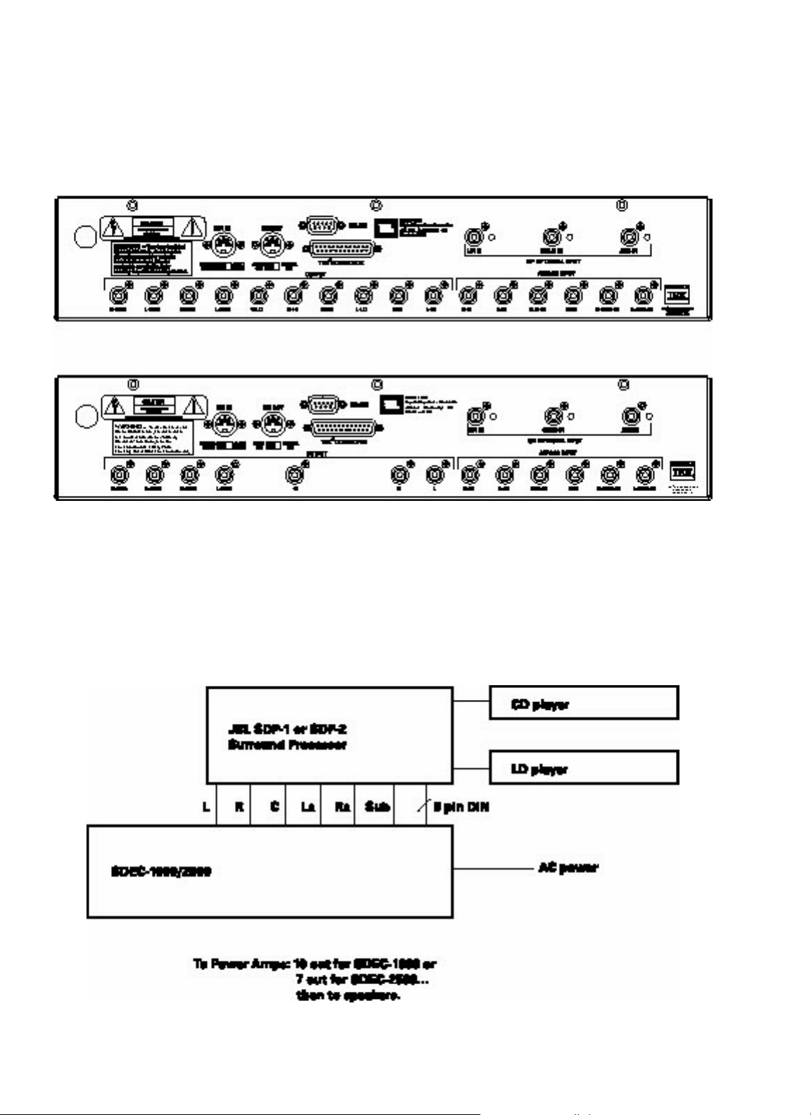
2.1
SDEC-1000 REAR PANEL
SDEC-2500 REAR PANEL
System connection after dealer
installation and calibration.
12
SDEC-1000 Rear Panel
SDEC-2500 Rear Panel
Page 13
2.2
WHAT THE SDEC DOES
13
The SDEC, available in two models that differ only slightly in function, is a digital signal processor capable of performing
several functions simultaneously. In general, the device is fed signals from the surround processor (the Synthesis SDP-1,
2 or 2D) that have been separated into discrete left, center, and right front channels, side and/or rear surround signals,
and subwoofer/lfe (low-frequency effects) signals.
By converting these six signals into digital bitstreams, and feeding them into a DSP (digital signal processing) engine
using extremely powerful Motorola processors, the signals can be manipulated in the digital domain to achieve several
desired results.
Driver correction, arrival time manipulation, room correction, and frequency division are some of the tricks easily done by
what amounts to a powerful, special-purpose computer, but which would require inordinate complexity (and would result
in signal-quality degradation) if done in the analog domain. After processing, high-quality digital-to-analog converters
return the signals to the analog domain, and pass them on to Synthesis amplifiers.
What the SDEC does:
Driver EQ:
The drivers used in Synthesis systems are designed and manufactured to reproduce both music and the audio associated
with cinema as faithfully as possible. But real-world mechanisms, however well crafted, have limitations imposed on their
operation due to the nature of available materials and the inescapable laws of physics. Because the SDEC is used only in
Synthesis systems and, therefore, is only used with a small number of different drivers, programs can be loaded into it to
smooth out response irregularities, compensate for manufacturing tolerances, etc. Tell the system during installation
whether it’s a Synthesis I, II, or III and corrections, programmed at the factory by JBL engineers, are instantly applied to
make very good drivers sound even better.
Figure 1:
Raw Driver Response/Corrected Driver Response
Page 14
2.2
WHAT THE SDEC DOES
14
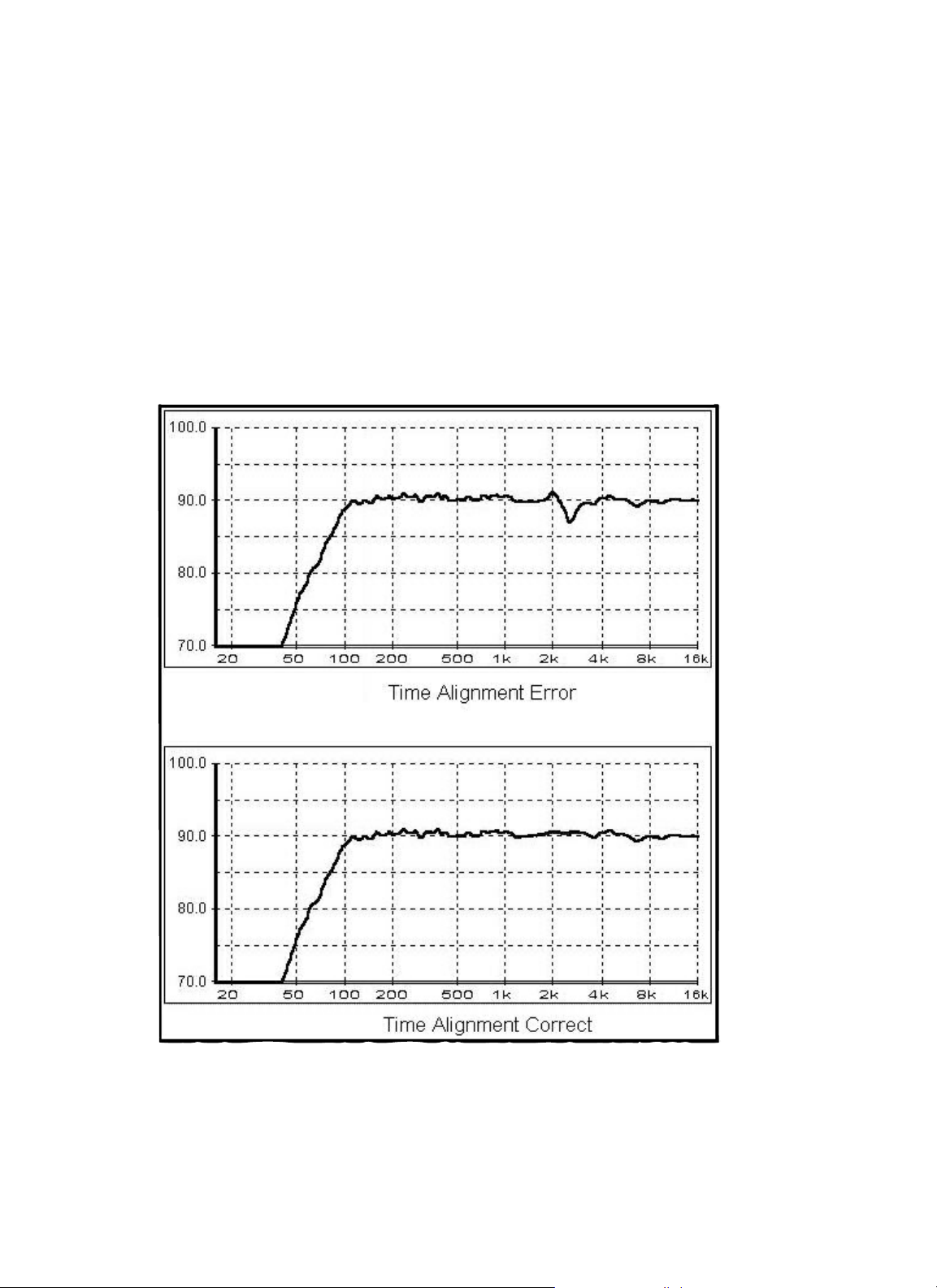
Driver Time Correction:
Once again, because the SDEC “knows” what speakers it’s being used with, it can correct for the different arrival times of
sounds from low- and high-frequency drivers. Arrival times are slightly different because the horns, tweeters, and
midrange drivers are mounted at somewhat different distances from the listener. The SDEC can delay the sound coming
from the closer drivers slightly, so that all frequencies impinge on the listener’s ears simultaneously, reducing acoustic
“smear”. All the frequency components that comprise complex waveforms arrive together; the end result is greater fidelity
to the original waveshape.
Figure 2:
System With and Without Driver Time Correction
Page 15
2.2
WHAT THE SDEC DOES
15
Channel to Channel Distance Correction (Auto-Time Correction):
The listener’s preferred listening location doesn’t always coincide with the “acoustically best” position; furniture placement, screen location, traffic patterns and other factors can keep us from sitting where “sound sounds best”, typically
determined by speaker placement geometry. The SDEC can compensate for unequal distances to loudspeakers and move
the “sweet spot” to the listener. This feature is called “Auto-time arrival correction” in the Synthesis system.
Figure 3:
Effect of Auto-Time Correction
Crossovers:
The SDEC-1000 (used in bi-amplified Synthesis I systems) performs the function of electronic crossover in addition to its
other tasks. This allows for more precise transducer correction and all other attendant advantages of bi-amplification. The
crossovers are 24dB per octave (4th order) Linkwitz-Riley type. This high-performance class of filter is rarely attempted in
passive crossover designs due to its inherent complexity.
Page 16
2.2
WHAT THE SDEC DOES
16
Screen Correction:
The computational power of the SDEC allows it to compensate for the effects of placing the front center channel
loudspeaker behind any of several popular types of projection perforated screen material.
Figure 4:
Effect of Screen Correction EQ
Modes:
Although not a major consideration before the advent of home theater, inherent differences exist between an
idealized music-only and an idealized cinema sound reproduction system. Cinema sound is produced with using
theater speakers that employ horn-loaded compression drivers. The directivity-index of horn-loaded drivers is significantly different from that of direct radiator designs. The best way to reproduce cinema audio is with speakers that exhibit
similar directivity characteristics.
Synthesis systems employ horn-loaded drivers for cinema and direct radiators for music.
The SDEC contains two sets of equalization curves selected by the system controller for each of the Synthesis I, II, and III
systems. Sources identified by the SDP-2 or the more recent DTS-equipped SDP-2D as music-only are fed through conventional midrange cone drivers and dome tweeters; theatrical audio is automatically fed to horn-based transducers, and
equalization is changed to the appropriate settings.
Room Correction EQ:
The parameter (or, more accurately, set of parameters) more responsible for overall sound quality than almost any other is
the acoustic signature, or characteristics, of the listening environment. Absolute room dimensions, the ratio of the room
dimensions, the shape of the room, absorption/reflection characteristics of the walls, and room furnishings can make
the most expensive equipment sound mediocre or enhance the sound of mediocre equipment. In this area, the SDEC is
Page 17

2.2
WHAT THE SDEC DOES
17
nothing less than magic! With 90 available bands of parametric equalization (each adjustable for center frequency,
amount of boost or cut, and bandwidth (the reciprocal of Q), its ability to address the specific problems of a given environment is far beyond any graphic equalizer. Typically, such devices are two-edged swords, able to cause at least as many
problems as they solve. In this case, however, a preprogrammed computer, using proprietary algorithms developed over a
period of several years by JBL, guides the automatic adjustment process, transforming acoustic torture chambers into
acoustically superior environments. The essential ingredient necessary for success is knowledge of what can and cannot
be corrected with equalization.
Figure 5:
Effect of Room EQ
Page 18

3.1
LOCATION, LOCATION, LOCATION ...
3.0
INSTALLING THE SDEC
18
Location, location, location…
(Please note that this installation guide assumes a U.S. location, in which the power source is 120 volt, 60Hz. JBL can
supply the SDEC for use in 230 volt, 50Hz environments on special order. Contact JBL for details and delivery information.)
Pick a location, determined by the relationship to other equipment and power availability. Note that there are NO user
controls on the SDEC: it need NOT be located where the user can easily reach it. Once programmed, it is turned On AND
Off by trigger signals from the Synthesis SDP-1, 2 or 2D, and, in turn, triggers the power amplifiers on and off. It can be
located close to the surround processor/decoder or close to the power amplifiers, although it should NOT be subject to
the heat they generate. For this reason, it may be better to locate it near the surround processor.
To simplify the following discussion, it will be assumed that the surround processor/decoder is a Synthesis SDP-2D,
although it may be an earlier SDP-1 or SDP-2. The SDP-1 is a Dolby
®
Pro Logic®decoder and control system, while
the SDP-2 incorporates the ability to decode AC-3
®
signals from DVD players or laser disc players equipped with RF
demodulators, such as the Synthesis SDP-RFD. The SDP-2D, the newest addition to the Synthesis family of controller/
processors, adds DTS decoding capability, while retaining AC-3 and Pro-Logic modes of operation. In subsequent
discussion, the word “controller” will be used to indicate the SDP-1, 2 or 2D, or whatever alternate equipment is being
used to select input sources and control power to ”downstream” pieces of signal processing equipment.
Frequently, the SDEC will be retrofitted to a Synthesis system previously equipped with an analog equalizer. It can
be mounted in place of the old equalizer and mode switching equipment, and will require considerably less space. A
minor amount of rewiring will be necessary. This is covered in CASE I, below. CASE II covers new installations of
Synthesis systems.
Page 19

3.2
A NOTE ON WIRING
19
A note on wiring:
There are four types of wiring systems associated with all Synthesis systems:
• Signal wiring: RCA-to-RCA type interconnects will serve to route analog audio signals between the surround processor,
the SDEC and the power amplifiers. Only high-performance interconnects should be used. A pre-fabricated set of cables
is provided with the SDEC. Any additional interconnects added to the system should be of equal or greater quality to
ensure trouble-free operation.
• Speaker wiring: Only high-performance, heavy gage speaker wire should be used. Any wire-runs through or within
walls must conform to local flammability requirements and be appropriately marked; CL-3 is one example of such
a rating. Refer to the Synthesis S-400/S-650 Power Amplifier User’s Manual for more information about selecting
appropriate speaker wires.
• AC power: It is recommended that the system be connected to a dedicated 20-amp AC circuit. If this is not an option,
try to avoid using an AC circuit that is shared with heavy appliances. Never connect any Synthesis equipment into a
switched outlet. Removing the AC power while the system is ON will cause no permanent damage, but may lock up its
microprocessors, necessitating turning the system fully off, then on again. It may also cause loud pops and clicks in
the loudspeakers.
• Control lines: All Synthesis components communicate with one another via a standard DIN connection cable. This
cable enables automatic power an mode switching of the entire system from the surround processor.
Page 20

3.3
WIRING CONNECTIONS TO THE SDEC
20
Wiring Connections to the SDEC:
Case I – Replacing an analog equalizer in an existing Synthesis system:
• Turn all equipment OFF and disconnect the AC power before beginning.
• Disconnect and remove the analog equalizers and all associated equipment, wiring and hardware.
• Physically install the SDEC. Refer to Section 3.1 “Location, Location, Location” for more information about selecting
an appropriate location for the SDEC.
• NOTE: Refer to Section 6 “Interconnection Diagrams” and Section 7 “Control Wiring Diagrams”. Locate the diagram
that illustrates the system you are installing. Use that diagram for the following steps.
• Confirm that all interconnects and control lines are connected as shown in Sections 6 and 7. All necessary control
lines and interconnects have been provided. If necessary, you may re use any applicable interconnects or control lines
removed from the analog hardware.
• NOTE: The DIN control line connections for the SDEC are significantly different from the analog EQ’s. Failure to
conform to the routing indicated in Sections 6 and 7 will cause control problems.
• There are 9-pin and 25-pin “sub-mini D” connectors on the rear panel of the SDEC. The 9-pin, labeled “RS-232” is
only for use during calibration and restoration activities; it is NOT intended for connection to home automation
systems, such as AMX or Crestron. The 25-pin is in parallel with the input jacks, following THX wiring convention.
It is not used with current Synthesis surround processors.
• On the rear panel of the SDEC are two slide switches with recessed handles. Unless you are installing a CINEMA-only
system, use a pencil or straightened paper clip to place both switches in the “AUTO” position. If you are installing a
CINEMA-only system, you must put the left switch in the ‘CINEMA MODE” position. This prevents the SDEC from ever
going into “MUSIC MODE” regardless of control signals received from the surround processor.
• NOTE: Mode -switching occurs as inputs are selected. Whenever the SDEC is asked to change modes, the system
output is muted for approximately two seconds while the appropriate equalization settings are loaded into the DSP.
This is analogous to loading a program into a computer.
• The right switch determines the mode of AC power control. Normally, the switch should be left in the “AUTO” (left)
position. In “AUTO”, the SDEC will be turned on and off by the surround processor. In the “MANUAL ON” (right)
position, the SDEC is controlled only by the front panel push button.
• NOTE: The “AUTO ON” feature only works when the front panel push button is pressed in. If this push button is
released, the SDEC will remain off.
• Connect the power cord of the SDEC to a suitable 120 volt, 60Hz power source. Refer to Section 3.2 “A Note on
Wiring” for additional information about AC power wiring. A red LED will illuminate the clear plastic escutcheon
surrounding the power switch.
• Reconnect the power amplifiers to their power outlets.
• Turn on all equipment except the surround processor.
• Test the system by turning the surround processor on.
Page 21

3.3
WIRING CONNECTIONS TO THE SDEC
21
• The first time SDEC is powered, it may take up to 30 seconds to “boot”. After system calibration is complete, boot time
is reduced to about ten seconds. When boot is complete, the red light around the power switch goes off, and an amber
LED in the center of the front panel comes on.
• Select an active program source. At this time, confirm that all channels are working. Now select another “effect” on the
surround processor that triggers a mode change. Confirm that all channels are still operating normally. Remember, as
the system is no longer calibrated, it probably will not sound the way it did when you started. If all channels are working
normally, you are now ready for connection to the Digital Audio Calibration System for complete equalization.
• If the system is not performing as expected, refer to “Troubleshooting” in Section 4.7.
Case II – Installing an SDEC as part of a new Synthesis system installation:
• Install the surround processor, signal sources, power amplifiers, and speakers appropriately. The SDEC can be located
near the surround processor or power amplifiers, but should not be subjected to excess heat; do not put it above an
amplifier in a rack unless excellent ventilation is provided. There are NO user controls on the SDEC; it is not necessary
to locate it within the operators reach. Its settings cannot be changed without the use of the DACS (Digital Audio
Calibration System) equipment.
• NOTE: Refer to Section 6 “Interconnection Diagrams” and Section 7 “Control Wiring Diagrams”. Locate the diagram
that illustrates the system you are installing. Use that diagram for the following steps.
• Confirm that all interconnects and control lines are connected as shown in Sections 6 and 7.
• On the rear panel of the SDEC are two slide switches with recessed handles. Unless you are installing a CINEMA-only
system, use a pencil or straightened paper clip to place both switches in the “AUTO” position. If you are installing a
CINEMA-only system, you must put the left switch in the ‘CINEMA MODE” position. This prevents the SDEC from ever
going into “MUSIC MODE” regardless of control signals received from the surround processor.
• NOTE: Mode -switching occurs as inputs are selected. Whenever the SDEC is asked to change modes, the system
output is muted for approximately two seconds while the appropriate equalization settings are loaded into the DSP.
This is analogous to loading a program into a computer.
• The right switch determines the mode of AC power control. Normally, the switch should be left in the “AUTO” (left)
position. In “AUTO”, the SDEC will be turned on and off by the surround processor. In the “MANUAL ON” (right)
position, the SDEC is controlled only by the front panel push button.
• NOTE: The “AUTO ON” feature only works when the front panel push button is pressed in. If this push button is
released, the SDEC will remain off.
• There are 9-pin and 25-pin “sub-mini D” connectors on the rear panel of the SDEC. The 9-pin, labeled “RS-232” is
only for use during calibration and restoration activities; it is NOT intended for connection to home automation
systems, such as AMX or Crestron. The 25-pin is in parallel with the input jacks, following THX wiring convention.
It is not used with current Synthesis surround processors.
• Connect each amplifier to its loudspeaker. Refer to Section 3.2 “A Note on Wiring” for additional information about
speaker wire selection.
• Connect all system components to a suitable 120-VAC power source. Refer to Section 3.2 “A Note on Wiring” for more
information about AC power connections. The SDEC will be in standby mode as soon as AC power is supplied.
Standby is indicated by red illumination of the escutcheon around the power push button.
Page 22

3.3
WIRING CONNECTIONS TO THE SDEC
22
• Turn on all equipment except the surround processor. At this time all Synthesis components should remain in standby.
• Now turn on the surround processor. After a few seconds, the Synthesis components should power up. First, the SDEC
will go from standby to on, followed by the amplifiers, one channel at a time.
• The first time SDEC is powered, it may take up to 30 seconds to “boot”. After system calibration is complete, boot time
is reduced to about ten seconds. When boot is complete, the red light around the power switch goes off, and an amber
LED in the center of the front panel comes on.
• Select an active program source. At this time, check that all channels are working. Now select another “effect” on the
surround processor that triggers a mode change. Confirm that all channels are still operating normally. If all channels
are working as anticipated, you are ready for connection to the Digital Audio Calibration System for equalization. Should
time not permit system calibration immediately, it can be used “as is” temporarily. The SDEC will simply pass signals
through with no signal processing.
• If the system is not performing as expected, refer to “Troubleshooting” in Section 4.7.
Power the system up for the first time:
With all power switches “off”, plug all equipment into power outlets. Turn on the SDEC by pressing the front panel push
button. Turn on the controller (typically first with a rear-panel master power switch, after which it will go through an initialization procedure, then from a front panel switch or remote control). The red light around the SDEC’s power switch should
go off and the yellow LED in the center of its front panel should light within 30 seconds. (After the SDEC is programmed,
the turn-on time is considerably shorter.) After a few seconds, the rest of the system should be on and ready for operation.
• Select a convenient source. The SDEC should route all channels to the appropriate loudspeakers, but will provide no
driver, time, or room correction.
• It is now ready for connection to the Digital Audio Calibration System for complete setup and equalization. Should
time not permit system equalization immediately, the system can be used “as-is” until the process can be completed.
The SDEC will simply pass signals through, with no equalization.
Page 23

23
4.1
OPERATIONAL OVERVIEW
4.0
THE DIGITAL ACOUSTIC
CALIBRATION SYSTEM
When the physical installation of any Synthesis System is complete, the next step is to calibrate the system to meet factory
performance specifications. This is accomplished with the use of the proprietary JBL Synthesis Digital Acoustic Calibration
System (DACS4). DACS4 is a computer controlled acoustic measurement system that communicates directly with the
SDEC-1000/2500. After each channel is analyzed, corrective settings are transmitted to the SDEC. These settings are
stored in non-volatile memory, thus assuring that the settings are permanent. Normally, re-calibration of an SDEC is not
required. There are no controls on the SDEC that can disturb the memorized settings.
Operational Overview:
Proper calibration of an audio playback system is a very complex undertaking. The first requirement is to acquire test data
that accurately portrays what is actually happening in the room. Second, we must post-process this data to create a view
that is relevant to what we actually hear. Third, this data must be compared to some theoretical ideal. Last, corrective
action must be taken to make the actual listening environment more closely match the ideal. Properly administering this
process is usually a good day’s work even for an experienced acoustics engineer using sophisticated analysis devices.
Using DACS4, you will be able to perform this work in a few hours time.
Stimulus:
DACS4 uses pink weighted pseudo-random noise to stimulate the speakers for each test. This stimulus is used because it
contains equal energy per octave, and all frequencies from 16Hz to 20kHz are represented. The stimulus level is preset to
generate a sound level of 85dBC when the system is properly calibrated.
Data Acquisition:
Meaningful acoustic measurements cannot be accomplished by placing a microphone at a single position in the room
and running a test. The key premise of room equalization at low frequencies is that the equalization will be used only to
correct for excessive energy found in specific room resonances It must not be used to correct for narrow, deep, dips
caused by destructive acoustical interference. A measurement made at a single point cannot effectively identify resonances and cannot discriminate against the relatively harmless acoustical interferences. The only effective method of
separating room resonances from acoustical interference is to sample the acoustic energy at several points in the room.
DACS4 employs five microphones distributed throughout the listening area. When the data acquired from these microphones is spatially averaged, the resultant curve has effectively “averaged out” most of the destructive interference
components while still reporting on major room resonances. This is so because acoustical interferences occupy very
Page 24

24
4.1
OPERATIONAL OVERVIEW
small spaces within the room (will only be seen on a single microphone) while low-frequency resonances will be found
over a much larger area. This technique assures that no single-point room anomaly will dominate the measurement
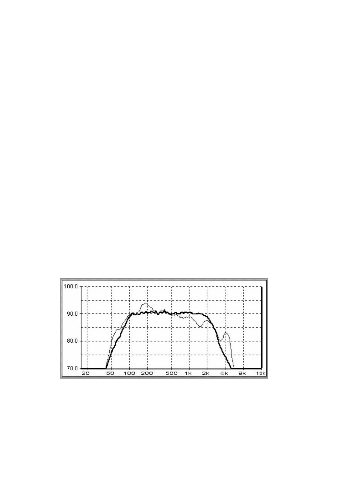
unless, of course, it is severe enough to exist at many locations, as resonances tend to do. As you can see in Figure 8,
the dips tend to average out, while the peaks get reinforced. Exactly what we want to do.
Figure 6:
System Response in Five Locations.
Lower Trace is the Spatially Averaged Result, Prior to EQ
Data Post-Processing:
A Microphone Multiplexer (SMM-5) scans the microphones sequentially and forwards the data to the EVP. All analysis
computations are performed in the EVP. The data from the individual microphones is spatially averaged into a single
block of data. This is a reliable indicator of the average frequency response of the system throughout the listening area.
To this energy vs. time data a Fast Fourier Transform (FFT) algorithm is applied. This conversion yields the familiar
amplitude vs. frequency data.
Page 25

25
4.1
OPERATIONAL OVERVIEW
Display Data:
DACS4 uses the laptop computer to display the results of each test. This data is plotted on an X-Y graph in a familiar
format, Amplitude vs. Frequency. In addition to the response data, there is also a “target” response curve present on
the same graph. The target curve is specific to the Synthesis model, mode of operation and channel being tested. This
allows you to quickly see how far from the ideal you actually are. As additional tests are performed, they can be added to
the display at will, allowing comparison between channels.
Make Corrections:
When you initialize DACS4, you input information about the Synthesis model being calibrated. With this, DACS4 loads
configuration information into the SDEC, which customizes it for use with the particular model, whether Cinema only
or Cinema + Music, and even compensates when the speakers are placed behind a perforated screen. At the same time,
appropriate target curves are loaded into memory.
DACS4 allows manual adjustment of as many as fifteen bands of parametric equalization. However, it is much easier to let
the computer do it for you. To this end, DACS4 incorporates a very sophisticated automatic EQ algorithm.
In addition, DACS4 performs auto-time correction. This routine determines the time arrival variance from channel to
channel and programs the SDEC to add delay as needed to normalize all channels to the same arrival time.
At the conclusion of the calibration session, all settings are transmitted to the FLASH EPROM in the SDEC and made
permanent (burned).
•Target Curves:
Intuitive logic would tend to indicate that the best sound would be achieved when the system delivers flat frequency
response. While this is true for all other components in the audio chain, this is definitely not true in the case of loudspeakers installed in listening rooms. There are several reasons for this, and it has taken many years of research to
establish just what the most desirable performance characteristics are.
• Ideal Low-Frequency Response
Room boundaries (walls, ceiling and floor) tend to contain low-frequency energy within the room. Simply stated,
this results in a boost in low-frequency energy. This is true whether it is a speaker or a piano producing the
sound. The exact frequency at which this effect begins and the amount of boost realized are a function of the room
size, shape and wall construction. No two spaces are ever exactly alike. This same low-frequency enhancement
also occurs in recording studios, and the recording engineers know this will occur during playback. They balance
their recordings in anticipation of this. Therefore, it would be wrong to “flatten” the speaker system response in
the playback environment. To do so only results in a thin bass sound.
By surveying many listening rooms over the years, JBL engineers have established a low-frequency response
characteristic that delivers the most consistently satisfactory results. This has been confirmed through extensive
subjective evaluation tests.
Page 26

26
4.1
OPERATIONAL OVERVIEW
Figure 7:
Synthesis 1 Main Target Curve, Below 1kHz
• Ideal High-Frequency Response
Above a few hundred Hz, the perception of sound quality, or timber, is determined by a complex combination of
the direct sound – the first arrival at the listener’s ears, the early reflected sounds – those sounds that have
reflected from the floor, ceiling and the side walls, and the reverberant sounds – sounds that arrive after many
reflections, from many directions over a period of time. Two ears and a brain are powerfully analytical of this
soundscape, and they arrive at a kind of “weighted” combination of them. All of the components are important,
but not equally so, and not always so, depending on the kind of sound that is being listened to.
We know, from many carefully controlled listening tests, that all three components must be timbrally-neutral in
order for a loudspeaker to be rated highly by listeners. The design criteria, therefore, can be summarized as “a flat
on-axis frequency response, with a directivity that is constant as a function of frequency”. This is something that
can only be measured properly in a laboratory, during speaker design. Once they are installed in a room, it is
difficult to impossible to make measurements that reveal this behavior of the speakers.
In a room, all of the sounds are mixed together, arriving at the measurement microphone at different times,
from different incident angles. While two ears and a brain deals with such sounds in different ways, the “dumb”
measurement system has no such discrimination capability. The room measurement, therefore, while not
entirely useless, is an unreliable indicator of what a listener hears except, perhaps, in the gross sense of
overall sound level.
Page 27

27
4.1
OPERATIONAL OVERVIEW
The fact that the “room curve” is not perfectly flat should not be upsetting. One would expect a gentle highfrequency rolloff from even the most perfect loudspeaker. The absorption of high frequencies by drapes, carpets,
upholstered furniture, etc. ensures that not all of the radiated energy reaches the listener, or microphone. it is
much the same in recording studios, so this is part of the normal playback circumstances. If the speakers have
been properly designed to begin with, it matters little what the room curve looks like at high frequencies.
Synthesis speakers are properly designed. In fact, attempting to adjust the room curve may undo a lot of careful
design effort on the part of the speaker engineers.
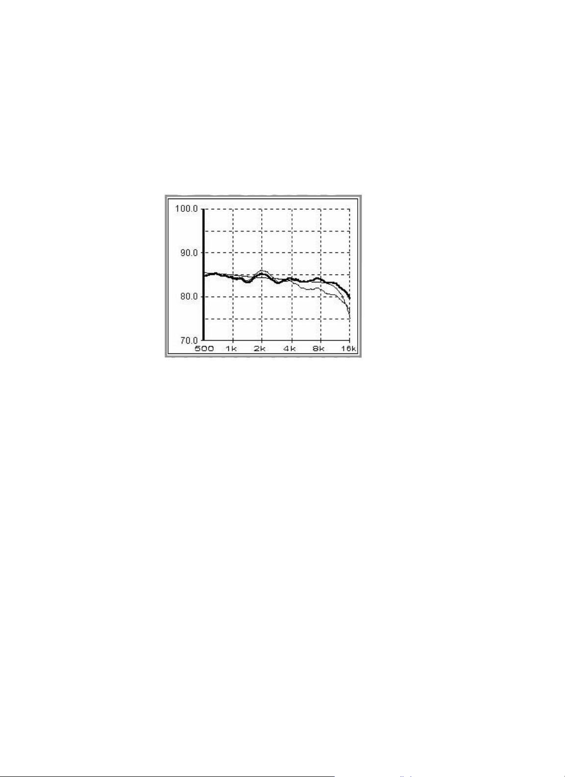
The Synthesis target curves are derived from data collected in many typical installations. They represent a trend
of what should be expected, not a specific shape that must be achieved for good sound. They help in the setting
of overall levels, and are useful for diagnostics or troubleshooting.
Figure 8:
Complete Synthesis 1 Target Curve
Page 28

28
4.2
DACS4 CONNECTIONS AND USE
DACS4 Connections and Use:
The following instructions are written on the assumption that the Synthesis system installation is complete and that basic
functionality of the system has been confirmed. If this is not so, please refer to the system installation documentation.
It is also assumed that the installation uses standard Synthesis components in a standard five-channel + subwoofer configuration. If this is not so, please refer to alternate configuration documentation or call your JBL Synthesis representative
for specific instructions.
Do not attempt to connect the DACS4 hardware to Synthesis while the system is on.
Things To Consider When Selecting A Location For DACS4:
The complete system calibration will take two-to-three hours; therefore, you should give the location of the test setup
some thought. Try to set up DACS4 in a comfortable location within the room to be calibrated. Here are some locations
to avoid:
1. Directly in front of any speaker
2. In a traffic lane
3. Any location that prevents you from seeing the SDP-2 front panel or the projector screen
4. Any location that interferes with remote control operation
5. In the main seating area (this is where the microphones will be)
6. On the floor
Whatever location you choose, use reasonable caution when laying interconnect cables around the room. Cables crossing
traffic lanes should be taped down to diminish the tripping hazard loose wires represent. Of course, this would also put the
DACS4 hardware in jeopardy.
Page 29

29
4.2
DACS4 CONNECTIONS AND USE
Hookup:
Use the following diagram to connect the DACS4 system to Synthesis:
Figure 9:
DACS4 Connection to Synthesis
• AC/Power Connections
The EVP-1 and the laptop computer use in-line power supplies. Connect these power supplies to their respective
devices before you connect them to the AC supply. The power connector for the EVP-1 is located on the left side of
the front panel while the connector for the laptop computer is located on the right side of the computer’s rear panel. If
possible, connect these supplies to the same AC circuit as the Synthesis System components. There is no power
switch on the EVP. When you plug the power supply into the AC supply, a red LED on the rear panel will light. Do not
power up the computer at this time.
Using the same AC outlet for all devices will minimize ground circuit current, which manifests itself as audible hum
in the speakers and popping noises during data transmission from the EVP-1to the SDEC. Some low level ACinduced noise is normal. This is because the DACS4 power supply and the laptop computer were not designed to be
high-quality audio devices. If you must connect the DACS4 hardware to a different AC circuit, the potential for hum is
greatly increased. When excessive hum is encountered, isolate the third wire ground connection of the EVP-1 power
supply from the AC supply.
Page 30

30
4.2
DACS4 CONNECTIONS AND USE
• Audio Connections
On the front panel of the EVP-1 are two RCA connectors labeled “RIGHT OUT” and “LEFT OUT”. Using the stereo
25' RCA cable provided, connect these outputs to the “AUX” input of the surround processor.
• Other Connections
A DB25 cable goes from the LPT1 output of the computer to the mating input connector labeled “COMPUTER” on the
back panel of the EVP.
Connect the 25' DB9 cable provided from the COM1 port on the back of the computer to the DB9 communications
port found on the back panel of the SDEC.
Now connect one end of the special 25’ cable provided between the DB9 connector on the rear panel of the EVP-1
labeled “MIC. BOX” and the round multi-pin connector found on the side of the SMM-5. Microphone connections will
be covered in detail in the “Microphone Connection and Placement” section of this manual.
Many of these connectors have security hardware which, when used, ensures trouble-free operation. Please resist the
temptation to attach the connectors without their security hardware. Although this will save you about two minutes during
setup, all too often the result is a crashed system or intermittent behavior, which results in a substantial loss of time. Keep
in mind that these connectors are subjected to far more insertions than normal. This accelerates wear, loosening the connector pin springs. These connectors are far more likely to fall out from the weight of the cable than it may appear.
•Microphone Connection and Placement
The DACS4 calibration kit includes five instrumentation microphones. Each microphone is placed on a telescoping
stand. The microphone cables are terminated with an Industry-standard male XLR connector. The barrel of the connector has a slot shaped cutout on one side, near the edge of the barrel. When the slot is facing up, you have the correct
orientation for insertion into the SMM-5. The mating jacks on the SMM-5 have a spring-loaded retainer key. When
you insert each microphone, you will hear and feel a click when the connection is complete. The retainer key prevents
accidental disconnection. To disconnect a microphone, you must press the key and pull the plug simultaneously.
In the event one or more of the microphones is placed beyond the reach of the cable, you can use the 2-meter
extension cables provided in the kit. Any standard four conductor XLR extension cable can be used for this purpose,
if necessary. It is recommended that the total length not exceed 9 meters.
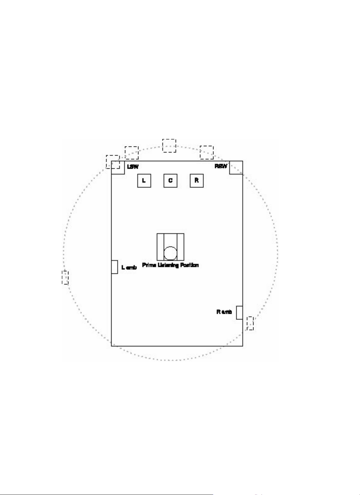
Room Placement
The SMM-5 is connected to and controlled by the EVP. When you perform a measurement, a discreet data block
is gathered from each microphone. These data blocks are then spatially averaged to create a single data block.
To ensure accurate measurements, it is vitally important that the microphones be placed optimally within the
listening area. See Figure 9 for basic placement guidelines.
Page 31

31
4.2
DACS4 CONNECTIONS AND USE
How is the Room Used?
Before you can decide microphone placement, you must know how the customer expects to use the room.
This is best determined by asking the customer some key questions. For example, ask if they typically entertain several guests when using the theater room. Appropriate microphone placement in this case would be to
distribute the microphones throughout the listening area. Conversely, if the most common use is just one or
two people, a much tighter placement pattern would be indicated.
Microphone #1
The first task DACS4 performs is Auto-Time Correction. The measurement system performs a quick test on all
speakers, using only microphone #1. The analysis of this data determines the distance from microphone #1 to
each speaker. The arrival time difference is removed by adding delay to each channel as needed. This has the
effect of placing the listener in the center of a circle, with all the speakers placed along its circumference. The
benefits are two fold. 1. Impulsive sounds have a more solid “attack” to them and, 2. Sounds that originate
from more than one speaker and are highly “correlated” will suffer far less “comb filtering” effects.
The primary listening position is the one seat in the room that is most often occupied. It may surprise you to
find that the primary position is not always the front and center seat. Wherever the primary position is, this is
where you will place microphone #1. You should place this microphone at ear level. The microphones are not
numbered and it does not matter which microphone you select for this position. What does matter is that you
plug the chosen microphone into position #1 on the SMM-5.
Now Place the Remaining Microphones
Figure 10 shows a typical seating arrangement. Gridlines have been added to this drawing to clarify the
discussion. Vertical lines are labeled numerically (X-axis) while horizontal lines are labeled alphabetically
(Y-axis). Whenever an X and Y line intersect, a coordinate point is established. For example microphone 1 is
at coordinate point E15. For best measurement results, never place more than one microphone on and X or Y
line. Since microphone 1 is at point E15, no other microphone should be placed along the E or 15 gridlines.
In this example, the other microphones are placed at points C10, L18, R5 and T25. No coordinate line has
been used more than once.
Tr y to keep any two microphones at least 1’ from each other. As a general rule, your imaginary grid spacing
should be no less than 6", with 12" or more being preferred. Two microphones closer than this would defeat
the desired effect. Try to keep the microphones as widely spaced as possible, but still within the listening area.
Following these guidelines assures that each microphone contributes a unique signature, and no axial room
mode will dominate the spatially averaged result.
Page 32

Figure 9:
DACS4 Connection to Synthesis
• AC/Power Connections
The EVP-1 and the laptop computer use in-line power supplies. Connect these power supplies to their respective
devices before you connect them to the AC supply. The power connector for the EVP-1 is located on the left side of
the front panel while the connector for the laptop computer is located on the right side of the computer’s rear panel. If
possible, connect these supplies to the same AC circuit as the Synthesis System components. There is no power
switch on the EVP. When you plug the power supply into the AC supply, a red LED on the rear panel will light. Do not
power up the computer at this time.
Using the same AC outlet for all devices will minimize ground circuit current, which manifests itself as audible hum
in the speakers and popping noises during data transmission from the EVP-1to the SDEC. Some low level ACinduced noise is normal. This is because the DACS4 power supply and the laptop computer were not designed to be
high-quality audio devices. If you must connect the DACS4 hardware to a different AC circuit, the potential for hum is
greatly increased. When excessive hum is encountered, isolate the third wire ground connection of the EVP-1 power
supply from the AC supply.
• Audio Connections
On the front panel of the EVP-1 are two RCA connectors labeled “RIGHT OUT” and “LEFT OUT”. Using the stereo
25' RCA cable provided, connect these outputs to the “AUX” input of the surround processor.
32
4.2
DACS4 CONNECTIONS AND USE
Page 33

Power Up Synthesis and DACS4:
After you have completed the connections described above, you are ready to power up Synthesis and DACS4. At this
point, the Synthesis system and the laptop computer should be off. The EVP-1, which has no power switch, should
already be on, as indicated by the red LED on the rear panel.
Turn the surround processor on first, allowing adequate time for all Synthesis components to come on.
1. Turn the surround processor’s gain control to minimum.
2. Turn on the laptop computer and wait for it to boot fully. When the boot is complete, there will be a message on the
screen asking if there is an SDEC 1000/2500 in this system. The computer will pause at this point, waiting for your
response. DO NOT respond at this time.
3. Select the AUX input on the surround processor. If you used a different input, select that one.
4. Slowly raise the gain of the surround processor, listening for any abnormal noises. This might be hum, pops, ticks,
sizzling, hissing or any other sound, that is abnormal or unexpected. Remember that some low-level hum and hiss is
normal, but it should be quite subtle. Continue raising the gain until you reach 0dB reference. If you hear nothing out
of the ordinary, proceed to the next step. If you do hear something that you suspect may be indicative of a problem,
turn the gain back down immediately and refer to the troubleshooting guide elsewhere in this manual.
4.3
POWER UP SYNTHESIS AND DACS4
33
Page 34

Preliminary Surround Processor Settings:
If this is the first time the system is being used, it is quite likely that the various user controls are still set to the factory
defaults. However, it is a good idea to make certain they are. There are two ways to do this.
1. Reset the surround processor. Instructions for doing this can be found in the surround processor operator’s manual
under “Restoring Defaults”.
2. Check each setting manually. They should be set as follows:
I. Global Settings:
A. Master Gain Control: 0dB
B. Speaker Configuration:
LEFT – CENTER – RIGHT, all models: Small, 80Hz high-pass
LEFT & RIGHT AMBIENTS, Synthesis 1: Small dipole, 80Hz high-pass
LEFT & RIGHT AMBIENTS, Synthesis 2 and 3: Small dipole, 100Hz high-pass
BASS SPLIT: 80Hz
REARS: None
SUBWOOFER: Yes, crossover set to 80Hz
C. All outputs levels set to 0.0dB
D. SUBWOOFER PEAK LIMITER: OFF
E. All surround processor EQUALIZATION settings should be as follows:
BASS: 0dB
TREBLE: 0dB
TILT: 0dB
LOUDNESS: OFF
F. LISTENER POSITION: 3’
II. Mode-Specific Settings:
A. Confirm the following settings for PRO-LOGIC mode:
AUTO AZIMUTH: OFF
DIALOGUE ENHANCE: 0dB
EFFECT LEVEL: 0dB
SUBWOOFER LEVEL: 0dB
SURROUND LEVEL: 0dB
B. Confirm the following setting for STEREO BYPASS mode:
SUBWOOFER LEVEL: 0dB
4.4
PRELIMINARY SURROUND PROCESSOR SETTINGS
34
Page 35

DACS4 Operation:
User Notes:
We have made every effort to develop a software package that requires a minimum of acoustic measurement experience
and is user friendly. For best results, you should possess a basic knowledge of the Windows
™
3.1x operating system and
use of a pointing device (mouse or track-ball). Some knowledge of MS-DOS is also helpful, but not essential. If you do
not have any experience with the Windows operating system, please review basic program conventions in the Windows
User's Guide.
Notational Conventions:
This manual, and the online help topics found in DACS4, will use the following notational conventions:
1. Keyboard references are noted in brackets. Here are some examples:
[Shift] = shift key
[Ctrl] = control key
[F1] – [F10] = special function keys
2. When two or more keys are to be pressed simultaneously:
[Ctrl]+[T]
[Ctrl]+[Alt]+[Tab]
• About Online Help
DACS4 has an extensive online help system. Topical information is continuously presented in a small window as you
work. The full text of each topic typically exceeds the size of the window. You can scroll through each topic using the
[PgUp] and [PgDn] keys. When you move on to the next step, the help field is automatically updated. Reading these
help topics thoroughly while working will guide you through the entire calibration process.
[F-1] Help
If the information presented online proves inadequate, more in-depth information on all topics can be found by
pressing [F1] any time during program execution. You cannot access the [F1] help topics when DACS4 is
performing a test or computing Auto-EQ.
Starting DACS4:
When you boot the DACS4 computer, it automatically begins the DACS4 program. DACS4 runs in Windows 3.1x. Prior to
starting the Windows operating system, program execution will pause, asking if there is an SDEC 1000/2500 in the system. Press [Y]es. Next, the computer will ask you to insert the blank disk provided with the SDEC into the drive slot “A”.
Do so now and press [ENTER]. At this time, the computer will load all necessary software on the disk to create a
“LOADER” utility disk. Leave the disk in “Drive A” throughout the calibration session. For more information about the
LOADER utility, refer to the “Maintenance” section of this manual.
35
4.5
DACS4 OPERATION
Page 36

• Initial DACS4 Screen
Figure 11:
DACS4 Opening Screen
This is the first and last screen displayed by the DACS4 System. You have three possible courses of action.
1. Run DACS2. This is the previous release of DACS, which is still suitable for calibrating any Synthesis System that
uses analog equalizers and crossovers.
2. Run DACS4.
3. Quit
Highlight the [SDEC] button and double click.
36
4.5
DACS4 OPERATION
Page 37

• Enter Customer Information
Figure 12:
Customer Information Window
The information you provide here performs two important functions. It attaches a customer and dealer name to the
test data that is saved by DACS4. This data is later used to create the Synthesis Calibration Certificate. Please take
care to enter the customer’s name exactly as he or she prefers. This is what will be printed on the certificate.
The information in section two is used to initialize the DACS4 program. Use care when selecting inputs. An incorrect
entry may go completely unnoticed until it is realized that the system just doesn’t sound right.
Use the [Tab] key to advance from one field to the next. If you wish to return to a previous field, press [Alt]+[Tab].
You must make an entry in all fields to run the program.
37
4.5
DACS4 OPERATION
Page 38

• Synthesis Model
Figure 13:
Customer Information: Select a Synthesis Model
Click on the [ ] button to expand the selection menu. Although there are only three Models of Synthesis, there
are actually seven possible permutations currently available, each of which requires a different calibration strategy.
• Select a Surround Processor
Figure 14:
Select a Surround Processor
Currently there is only one choice. Therefore, DACS4 will skip over this menu. In the future, when other surround
processor models are added, you will need to select one from this list.
38
4.5
DACS4 OPERATION
Page 39

• Center Screen Compensation
Figure 15:
Identify Screen Type, Center Channel
If the Center Channel speaker is behind a perforated screen or decorative cloth, you can add screen compensation
to the SDEC. Select the appropriate screen: Cloth or None. If you are using a perforated screen or cloth not listed
here, call your Synthesis Representative.
• Left/Right Screen Compensation
Figure 16:
Identify Screen Type, Left & Right Front
Similarly, select the appropriate entry for the Left and Right front speakers.
After you have entered the required information you may press [Enter] or click on [
✔
OK] button to advance to the
next screen.
39
4.5
DACS4 OPERATION
Page 40

• Confirm DACS4 Connections
Figure 17:
DACS4 On-Screen Wiring Diagram
Before DACS4 runs, this simple hookup diagram is provided for your review. Please take a moment to confirm
that these connections are correct. Press [Any Key] when you are ready to continue.
40
4.5
DACS4 OPERATION
Page 41

DACS4 Main Screen:
The following is an overview of the features and control facilities available on the main screen.
Figure 18:
DACS4 Main Calibration Screen
This is the main Synthesis calibration workspace. Before you begin calibration, take a few minutes to familiarize yourself
with the eight different communication fields represented on this screen.
4.6
DACS4 MAIN SCREEN
41
Page 42

Response Graph:
Figure 19:
Response Graph Window
This area of the screen will display the results of each test, overlaid on the target curve. Amplitude, in dB, is indicated
vertically (Y-axis) and frequency, Hz, is indicated horizontally (X-axis). The heavy vertical line at 100Hz is the cursor
location. It indicates the center frequency of the active filter. Numerous curves can be displayed simultaneously.
Filters at a Glance:
Figure 20:
Filter Setting and Control Field
The settings of all filters can be reviewed here. Each filter’s center frequency is indicated in the small box above each bar
graph. Each bar graph gives an indication of relative boost or cut. The width of each bar indicates the relative “Q”, or
bandwidth, of each filter. Finally, the highlighted filter is the currently “active” filter. Active, in this context, means the filter
whose parameters can be adjusted. Only one filter can be active at a time.
Individual Filter Control:
4.6
DACS4 MAIN SCREEN
42
Page 43

Figure 21:
Filter Control Field
The currently active filter’s parameters can be precisely adjusted here. Any desired center frequency can be entered in the
frequency box. Mouse clicking on the bandwidth bar will toggle through all available filter bandwidths. Click the mouse
pointer over the slider on the left and you can raise or lower the gain of the filter. Alternately, you can enter any desired
level of boost or cut (within the allowable range) directly in the dB box.
Channel and Mode Selection/Status:
Figure 22:
Direct Channel and Mode Access
The status of all channels is indicated here. Each channel is designated as follows: S = subwoofer; L, C, R = left, center
and right; AL, AR= ambient left and right The currently active channel is indicated by a black dot in the diamond above
each channel designator.
Any channels that have been completed are indicated as such by a black check mark in the diamond above each channel.
The example in Figure 22 indicates that the subwoofers have already been calibrated.
You can jump directly to any channel and begin a test by clicking the mouse pointer on the diamond of the channel you
want to test next.
The currently active mode (Music or Cinema) is indicated by the solid black text and a black dot to its left. Conversely, the
inactive mode is shadowed.
Depending on the conditions under which you are testing, you may also switch between Music and Cinema modes by
clicking the appropriate circle to the left of each mode.
4.6
DACS4 MAIN SCREEN
43
Page 44

Overlay Previously Tested Channels:
Figure 23:
Channel Display Control Field
When you perform a test on any channel, the corresponding text in this communication field turns solid black, indicating that
it is available for display. To display a previously tested channel, click the mouse pointer on the box to the left of any available channel. A check mark will be placed in the box, indicating that this channel is being displayed. Available channels can
also be displayed by pressing the letter key corresponding to the underlined letter in each available channel.
Online Help:
Figure 24:
Continuously Updated Online Help
Topical information is continuously presented here as you work. The full text of each topic typically exceeds the size of the
window. To review the text in its entirety, use the [PgUp] and [PgDn] keys to scroll through the displayed topic. When you
move on to the next step, this help field is automatically updated. Reading these help topics thoroughly while working will
guide you through the entire calibration process.
Special Function Keys:
There are eight function keys used. Their function can be initiated by either pressing the function key itself, or clicking on
them with the mouse pointer.
Figure 25:
Function Keys and Status Line
4.6
DACS4 MAIN SCREEN
44
Page 45

[F1] HELP This is a compilation of help topics, tips and tricks on nearly every aspect of DACS4 operation.
[F2] AUTO–EQ Initiates automatic equalization of the active channel
[F3] ACCEPT Press [F3] when you have completed all adjustments on the active channel. Pressing [F3] transmits the
final settings to the SDEC, and puts a check mark in the channel status indicator.
[F4] TEST Runs a test of the currently active channel.
[F6] EXIT Program Quit.
[F7] Room EQ Inserts a special EQ instruction dialog in the online help window
[F8] GAIN/DELAY Pops up a dialog box that displays the current gain setting and the microphone-to-speaker
distance for all channels.
Figure 26:
Channel Gain and Delay Information
4.6
DACS4 MAIN SCREEN
45
Page 46

Calibration Walk-Through:
If you have read everything up to now, and done everything suggested, you should be looking at this screen on the
DACS4 computer.
Figure 27:
Fresh Install, First Screen
Now would be a good time to begin reading the information presented in the online help field. It will guide you through
the entire calibration process. When you have finished familiarizing yourself with this information, press the [Spacebar].
You will not be able to proceed until the [Spacebar] is pressed.
4.7
CALIBRATION WALK-THROUGH
46
Page 47

Auto-Time Correction:
The first test you will perform, Auto-Time Correction, will briefly stimulate each speaker to determine the distance from
microphone #1 to each speaker. Press [Ctrl]+[T] to run the test. Immediately after the test a dialog box, which reports the
measurement results, will appear.
Figure 28:
Auto-Time Correction Dialog Box
Gain and distance information for all channels is displayed. Along the left, arranged vertically, is a list of channels. The left
and right columns display the gain settings for each channel. The center column displays the results of the Auto-Time test.
In some circumstances, the measured distance may be incorrect. It is recommended that you take a moment to confirm
that the measurements are correct. A normal tolerance for these measurements is +/
–
6". Typically, if there is an error, it
will be quite large, so it is easy to spot. As an example, If all of the speakers are about 200" from MIC #1, one channel
might report 360" or 0".
If one or more channels are misreported, simply use a tape measure to determine the correct distance (from MIC #1 to the
grille of the speaker) and manually enter the correct distance for that channel.
When this dialog box occurs, the left channel distance entry field is already highlighted. If this channel requires correction, you can type it in. If one of the other channels requires editing, press [TAB] key as often as necessary to advance
to the desired channel. Or press the [TAB] key repeatedly until the correct entry field is highlighted. Now type in the
correct distance.
When you are finished, press [F8] to clear this dialog box.
The gain settings found here may or may not be needed at a later time. In any event, they are not to be changed from their
current settings now.
4.7
CALIBRATION WALK-THROUGH
47
Page 48

Cinema, Subwoofer Calibration:
Figure 29:
Ready for Sub-Woofer Level Test
Before attempting equalization of any speaker, it is necessary to have the level preset so the unequalized response plot fits
as well as possible over the target curve. This is necessary for two reasons.
1. The Industry-standard reference level is 85dBC when the source (DVD or LaserDisk) is at 0dB. Setting this test to fit the
target will bring you very close to calibrated level.
2. The DACS4 equalizer has a gain range of +6 to –12dB. If any response peaks/dips are beyond that range, it will not be
possible to correct.
4.7
CALIBRATION WALK-THROUGH
48
Page 49

• Setting The Level
The first test you run on each channel is totally uncalibrated. The sound level could be several dB high or low and the
response may be very irregular. This extreme irregularity can make it quite difficult to determine how much the level
needs to be shifted. DACS4 has a special display-smoothing algorithm designed to make it easy to determine the
correct level. You invoke the smoothed display by pressing the [Shift]+[F4] keys. This will initiate a test and display
the results with smoothing. Check that the surround processor’s main level control is at 0dB. Press [Ctrl]+[F4] now.
Figure 30:
Setting Level
Figure 31:
Without Smoothing Filter
4.7
CALIBRATION WALK-THROUGH
49
Page 50

Figure 30 illustrates the results one might expect from using [Shift]+[F4] to set level. The fine upper trace is the first
test, the lower trace is the second test with the subwoofer output lowered 5dB. Figure 31 illustrates the same test
conducted using only [F4], which performs a standard resolution test. This subwoofer is now ready for equalization.
You may repeat the [Shift]+[F4] and/or [F4] as often as necessary to produce the desired result.
• Auto-Equalization
When you have performed the tests and adjustments described above, you should have something similar to
Figure 31 on the DACS4 response graph. You are ready to initiate the Auto-EQ routine. Press [F2] now.
Figure 32:
Results of Auto-EQ
Figure 32 illustrates the results of Auto-EQ. Notice the remaining small peaks and dips at the top of the graph. With
10 bands of parametric equalization and some determination, these can be removed completely. Doing so dramatically increases the computation time needed. Additionally, small, high “Q” anomalies such as these have been found
to be inaudible. Therefore, the Auto-EQ algorithm makes no attempt to correct them.
When you are satisfied with the performance of the subwoofers, press [F3]. [F3] transmits the final settings for this
channel to the SDEC, places a check mark in the diamond above the subwoofer channel-status indicator and
advances to the Left Cinema channel, ready for additional tests.
4.7
CALIBRATION WALK-THROUGH
50
Page 51

Cinema, Left – Center – Right Calibration:
The procedure in the steps above is substantially repeated for all subsequent channels. The topics that follow will focus
on the differences. Steps that have already been explained will be listed only.
• Setting The Level
[Shift]+[F4]: Adjust level, repeat as needed.
DACS4 performs no equalization at high frequencies. Therefore, when setting the level, focus your attention above
1kHz. The following table illustrates the relative importance of selected frequency ranges.
Table 1:
Level Set Tolerance vs. Frequency
Table 1 demonstrates that it is most important to fit the test over the target as well as possible from 4 to 8kHz. The
frequencies above and below are less critical but cannot be ignored. Every room exhibits different high frequency
absorption characteristics, and every possibility cannot be anticipated in this document. Use your judgment when
in difficult or unusual environments.
Some rules of thumb:
1. The perception of “brightness” usually originates in the 4 to 8kHz region.
2. Significant variations (±3dB) above 8kHz are far less noticeable.
3. Low “Q” (wide bandwidth) response variations are much more audible than high “Q” variations. Always correct
low “Q” errors first.
Figure 33:
Left Cinema Level Set
4.7
CALIBRATION WALK-THROUGH
51
Page 52

• Run Auto-EQ
[F2]: Perform Auto-EQ.
DACS4 performs Auto-EQ only below 800Hz. Beyond correctly setting the level, no attempt is made to equalize
above 800Hz. You may observe significant response variations above 800Hz. As explained earlier in this manual, this
is a normal consequence of speakers interacting with the room. Attempts to EQ the high frequencies only degrades
system performance.
Figure 34:
Auto EQ
[F3]: Accepts settings.
Left and Right Ambient Calibration:
The calibration procedure for the ambient speakers is slightly different from the main speakers. This is because they are
dipoles, designed to minimize direct radiation in favor of diffused reflections. Also, their location, at the sides of the room,
has a very different effect on the ear/brain mechanism.
4.7
CALIBRATION WALK-THROUGH
52
Page 53

• Setting The Level
The default display mode for the ambient speakers includes a one-octave smoothing filter. Therefore, it is not
necessary to use [Ctrl]+[F4] to set the level.
[F4]: Set level. Repeat as needed.
The target curve is significantly different. Because of the very different nature of the speakers, the range of equalization
is 100Hz to 5kHz. In addition, when setting the level, it is best to match the level over the entire range of the speaker.
Figure 35:
Ambient Target
[F3]: Accept results.
If you are calibrating a Cinema only system, accepting the last channel signals the end of the calibration sequence.
Skip forward to the topic “Quitting DACS4” on page 54.
If you are calibrating a Cinema + Music system, read on.
Music Mode Calibration:
As soon as you accept the last channel in Cinema mode, DACS4 automatically reconfigures itself for calibration of the
Music mode speakers. Follow the instructions presented on the DACS4 screen during this transition.
There is no need to calibrate the center channel or the ambient speakers. They were calibrated previously.
You will calibrate the subwoofers and the left and right front speakers. The targets are different, but the procedures are
the same.
4.7
CALIBRATION WALK-THROUGH
53
Page 54

Quitting DACS4:
• After a Complete Calibration
When you have accepted the last channel, DACS4 will automatically transmit all settings to the SDEC and those
settings will be burned to the nonvolatile FLASH memory.
[F6]: Quits DACS4
Follow the instructions on the DACS4 screen to quit the program. Remove the “Loader” utility disk from the
DACS4 computer and store it in a safe location at the installation site. All the usual admonitions about dust, heat
and humidity apply to the choice of storage location.
• Quitting When Some Channels Are Not Accepted
If you must terminate a session before you have completed calibration, press [F6]. You will be warned that quitting
before completion of the job will lose any settings you may have completed at this time. You will be given an opportunity to reverse your decision to quit. If you click [Cancel], you will be returned to the program. If you click [OK], all
settings will be discarded and the program will be terminated.
SDEC Maintenance:
• Using The Loader Utility
When you began the SDEC calibration process, DACS4 asked you to install the 3.5” floppy disk provided with the
SDEC. After calibration is complete, this disk will contain a file that contains all settings made to the SDEC during
calibration. Leave this disk at the installation site, using conventional precautions about dust, heat and humidity.
In the event the SDEC needs to be replaced, you will use this disk to load the calibration settings into the replacement SDEC. To do this you will need a portable computer running Windows 3.xx or Windows 95. It must have an
available COM port and a high-density disk drive. Use the following procedure to load the settings.
1. With everything off, connect a standard DB9 (9-pin) cable between the computer’s COM port and the connector
located on the rear panel of the SDEC.
2. Turn on the SDEC.
3. Boot the computer to Windows.
4. Insert the disk.
5. Click on File, Run.
6. Type A:loader.
7. Press [Enter].
8. Wait patiently. When the settings have been successfully transmitted and burned into the SDEC memory, a
“DONE” dialog box will pop-up.
9. Turn everything off, remove the disk and return it to storage. Install the new SDEC.
4.7
CALIBRATION WALK-THROUGH
54
Page 55

Troubleshooting:
• Correcting Hum Problems
Reading this will help you avoid hum problems in any Synthesis Home Theater System installation. It really isn’t
very difficult to do, but you will need to take some preventive measures during system installation to prevent it.
Why Does It Hum In The First Place?
Anytime you interconnect two analog audio signal devices, and they each have their own AC cord, you can
potentially generate some hum. When you interconnect several devices, as is the case in a Synthesis system,
the potential is many times greater.
All audio signal devices must reference their internal circuitry to “ground” in order to establish a zero voltage
“reference” point for all active circuitry. In reality, it is not necessary for any isolated piece of equipment to be
connected to “earth ground”. An airplane is a good example of such a situation. The need to connect home equipment to earth ground is based on safety concerns. It is essential that a path to earth ground be provided, as a
drain of unwanted potential. An example of this would be a lightening strike or an insulation failure within a piece
of equipment. Since the system must be earth grounded to maintain safety (and in many states, to be legal), this is
the logical place to begin.
When two or more audio devices are interconnected, they must have precisely the same zero voltage reference
point or you may encounter problems. When you hear hum, this is an indication that one or more of the devices
in the audio chain has a slightly different ground reference potential. This is what we must correct to eliminate
audible system hum. There are many “bad science” solutions out there. Please resist the temptation to experiment
with them, ultimately, they will not be fully effective, in some instances equipment can be damaged, they may
actually be illegal and in many cases are downright dangerous.
What You Can Do During Installation
First, do not isolate the third wire ground at the AC plugs. This is essential for safety as well as proper hum
reduction. Make certain this connection is as good as possible. The goal is zero resistance to the ground outlet.
Theoretically, this should be enough to prevent hum problems, but it isn’t always. Occasionally, the house wiring
does not provide a low enough resistance between components to be totally effective. Particularly when more than
one AC outlet is used. High resistance house wiring can be caused by oxidized or loose wiring connections, or
even improperly wired outlets. Correcting the house wiring may not be an option, and even then you may
encounter difficulty. You do not need to correct the house wiring to get the desired results.
It may be necessary to tie all of the hardware together electrically so there is no ground potential difference
between the various devices and third wire ground from the AC outlet(s). Even a few microvolts difference will be
audible. This is why you must create the lowest possible impedance ground path between all of the equipment.
Zero impedance = zero volts.
One very effective way of accomplishing this is by mounting the devices into a metal equipment rack. Most equipment racks and the hardware you are installing are painted or anodized. These finishes will prevent a good
ground. When installing the equipment, file or sand the rack and the panel where they will contact each other until
you have a clean, metal to metal contact. Alternatively, you can put an unused external shakeproof lock washer
(sometimes called a star washer) between the rack and the panel with each mounting screw. This will cut through
the finish as you tighten the hardware.
4.7
CALIBRATION WALK-THROUGH
55
Page 56

If the SDP-2 surround processor is not being mounted directly to this rack you may need to fabricate a ground
strap using 16 or heavier gage stranded wire with crimp-on ring lugs on the ends. Securely attach one end of the
ground strap to the SDP-2 using the center top cover retaining screw (found on the rear) as an attachment point.
Attach the other end of the ground strap to the metal equipment rack, in a central location, close to the other
devices in the rack. Make certain the finish on the rack is not insulating the connection.
If mounting the devices in a metal equipment rack is not an option, you may need to fabricate ground straps and
tie some or all of the devices together. Use 16 gage or heavier stranded wire, with crimp-on ring lugs at each end
of the wires. In this instance you will want to create a “star” grounding pattern. This means that each device will
have a ground wire attached directly to the same screw on the SDP-2 surround processor chassis. The center top
cover retaining screw on the back of the SDP-2 can be used for this purpose.
In some difficult installations, you may find it necessary to use a combination of both techniques described above.
Whatever the details of the particular installation, you must reduce all ground path resistance to as close to 0W as
possible. This is the correct method of eliminating hum. Do not try to “break” the ground by defeating the ground
connection on the AC plug. Although this sometimes appears to improve the audible hum, you are actually creating a potential for much more serious problems associated with floating grounds. Pops and clicks can be one
result. More serious, changes in the AC (from large appliances or peak power usage for example) can cause the
hum to return intermittently after you have left. This can be a real service headache.
Video Devices
Video devices represent a special challenge. This is because they are frequently connected to externally grounded
sources, like cable TV service. Projectors are never installed close to the other equipment, so they are almost
always plugged into a different AC circuit. This is a number 1 cause of ground current related problems. In the
case of cable TV service, one solution is to strap the incoming cable shield directly to the AC receptacle ground.
Another, perhaps easier approach is to install an isolation transformer.
If the source of hum is the remote AC connection of the projector, the best solution is to pull a 12-gage ground
wire along with the video cables. Connect this ground wire between the chassis of the projector and the SDP-2.
4.7
CALIBRATION WALK-THROUGH
56
Page 57

THD + Noise 0.02% @ 1kHz 0.02% @ 1kHz
Frequency Response <15hz –20kHz +0 ,–1db <15hz –20kHz +0 ,–1db
S/N Ratio ( A-weighted) 100db ref: max output 100db ref: max output
Dynamic Range 114dB 114dB
Input Level Range 15µV – 8V 15µV – 8V
Input Impedance 10k ohms 10k ohms
Output Impedance 50 ohms 50 ohms
Crossover 4th order Linkwitz-Reilly N/A
Filter Characteristics
Attenuation Range +6db, –12dB +6db, –12dB
Center Frequency Range 20Hz – 20kHz 20Hz – 20kHz
Bandwidth 0.1 – 5 octaves 0.1 – 5 octaves
Total Bands Provided 90 90
Unit Size 3.5"H x 19"W x 18"D 3.5"H x 19"W x 18"D
Unit Weight 22 lbs. 22 lbs.
Power Required 40 watts, max. 40 watts, max.
All features and specifications are subject to change without notice.
SDEC-1000 SDEC-2500
5.0
SPECIFICATIONS
5.0
SPECIFICATIONS
57
Page 58

SYNTHESIS ONE Interconnection Diagram
S400
S400
S650
S650
SDP-2D
SDEC-1000
SDP-RFD
58 59
6.0
INTERCONNECTION
DIAGRAMS
Page 59

SYNTHESIS TWO/THREE Interconnection Diagram
S650
SDP-2D
SDEC-2500
S400
SDP-RFD
60 61
6.0
INTERCONNECTION
DIAGRAMS
Page 60

SYNTHESIS ONE Control Wiring Diagram
SDP-2D
SDEC-1000
S400
S400
S650
S650
SDP-RFD
62 63
7.0
CONTROL WIRING
DIAGRAMS
Page 61

SYNTHESIS TWO/THREE Control Wiring Diagram
S650
SDP-2D
SDEC-2500
S400
SDP-RFD
64 65
7.0
CONTROL WIRING
DIAGRAMS
 Loading...