

Page 1

STC-1
PROGRAMMABLE
TOUCH SCREEN
REMOTE
OWNER’S
GUIDE AND
PROGRAMMING
MANUAL
®
Page 2

Page 3

SECTION _________________________________________ PAGE
1.0
_______________ INTRODUCTION
1.1 Features 4
1.2 Important Notes 4
1.3 Getting Started 4
1.4 The Touch Screen Display 5
1.5 The Special Functions Page 5
1.6 Battery Recharging and Control 6
1.7 Programming the STC-1 6
1.8 Setting the Access Options 7
2.0 ________CREATING AND EDITING PAGES
2.1 Creating a Page 8
2.2 Editing a Page 8
2.3 Placing Buttons on a Page 9
2.4 Using the Text Editor 10
2.5 Assigning a Page to a Button 11
2.6 Removing a Page Assignment from a Button 11
2.7 Deleting a Button from a Page 11
3.0 ________IR EDITOR
3.1 Menu Options 12
3.2 Aligning a Remote Control 13
3.3 Sending Infrared Commands to the STC-1 14
3.4 Testing Infrared Commands 14
3.5 Editing Infrared Commands 14
4.0 ________MACRO EDITOR
4.1 Menu Options 15
4.2 Editing a Macro 15
4.3 Inserting an Infrared Command 16
4.4 Inserting a Time Delay 16
4.5 Macro Hints 17
5.0 ________IR CODE BASICS
5.1 Frequency Modulation 18
5.2 Pulsed IR Codes 18
5.3 How the STC-1 Learns IR Commands 18
5.4 Hints for Learning IR Codes 19
6.0 ________PROGRAMMING HINTS
6.1 Summary: Creating Pages 21
7.0 ________TROUBLESHOOTING
7.1 Contacting JBL 22
8.0 ________SPECIFICATIONS 23
APPENDIX A: SCREEN TEMPLATES 24
INDEX 25
WARRANTY 28
TABLE
OF
CONTENTS
Page 4

UNPACKING
AND INSPECTION
After unpacking the STC-1, save all of the packing
materials in case you ever need to ship the unit.
Thoroughly inspect the STC-1 and the packing materials
for signs of damage. Report any shipment damage to the
carrier at once. Report any equipment malfunctions to
your dealer.
Precautions
This equipment has been tested and found to comply
with the limits for a Class B digital device, pursuant to
Part 15 of the FCC Rules. These limits are designed to
provide reasonable protection against harmful
interference in a residential installation. This equipment
generates, uses, and can radiate radio frequency energy
and, if not installed and used in accordance with the
instructions, may cause harmful interference to radio
communications. However, there is no guarantee that
interference will not occur in a particular installation. If
this equipment does cause interference to radio or
television reception, which can be determined by turning
the equipment off and on, the user is encouraged to try
to correct the interference by one or more of the
following measures:
• Reorient or relocate the receiving antenna.
• Increase the separation between the equipment and
the receiver.
• Connect the equipment into an outlet on a circuit
different from that to which the receiver is connected.
• Consult the dealer or an experienced radio/TV
technician for help.
2
▲WARNING
TO REDUCE THE RISK OF FIRE OR ELECTRIC SHOCK,
DO NOT EXPOSE THE UNIT TO RAIN OR MOISTURE.
▲WARNING
THIS UNIT CONTAINS NICKEL-CADMIUM
BATTERIES. RECYCLE OR DISPOSE OF PROPERLY.
Page 5

Read Instructions. Read all safety and operating
instructions before operating the unit.
Retain Instructions. Keep the safety and operating
instructions for future reference.
Heed Warnings. Adhere to all warnings on the unit
and in the operating instructions.
Follow Instructions. Follow operating instructions
and instructions for use.
Heat. Keep the unit away from heat sources such as
radiators, heat registers, stoves, etc., including
amplifiers that produce heat.
Ventilation. Make sure that the location or the position
of the unit does not interfere with its proper ventilation.
For example, the unit should not be situated on a bed,
sofa, rug, or similar surface that may block the
ventilation openings, nor should it be placed in a
cabinet that impedes the flow of air through the
ventilation openings.
Power Sources. Connect the unit only to a power
supply of the type described in the operating
instructions, or as marked on the unit.
Power Cord Protection. Route power supply cords
so that they are not likely to be walked on or pinched by
items placed on or against them, paying particular
attention to the cords at plugs, at convenient receptacles,
and at the point at which they exit from the unit.
Nonuse Periods. Unplug the power supply from the
outlet when the unit is to be left unused for a long
period of time.
Water and Moisture. Do not use the unit near
water–for example, near a sink, in a wet basement, near
a swimming pool, near an open window, etc.
Object and Liquid Entry.Do not allow objects to fall
or liquids to be spilled into the enclosure through
openings.
Cleaning. The unit should be cleaned only as
recommended by the manufacturer.
Servicing. Do not attempt any service beyond that
described in the operating instructions. Refer all other
service needs to qualified service personnel.
Damage Requiring Service. The unit should be
serviced by qualified service personnel when:
• The power supply cord or the plug has been damaged.
• Objects have fallen or liquid has been spilled into the
unit.
• The unit has been exposed to rain.
• The unit does not appear to operate normally or
exhibits a marked change in performance.
• The unit has been dropped, or the enclosure damaged.
SAFETY
SUGGESTIONS
3
Page 6
The STC-1 is a PROGRAMMABLE TOUCH SCREEN
REMOTE
that is designed to provide wireless control of
audio/video and automation systems. Like other
“universal” or “learning” remote controls, the STC-1
allows you to consolidate the functions of many
independent infrared remote controls into one unit.
However, the STC-1 also incorporates a unique
programmable user interface, allowing it to provide a
simple, intuitive, and customized interface for any
system. Before using the STC-1, please read and follow
all instructions in this manual.
1.1 Features
The STC-1 provides superior quality and reliability as
well as these specific features:
• A replacement for all of your system’s remote controls.
The STC-1 can reproduce all of the commands of
almost any other infrared remote control.
• A programmable graphic display. The STC-1 has a
built-in drawing program that makes it easy to place
buttons, text, and symbols anywhere on the display.
• A touch-sensitive display. When you want to perform
a command, simply touch the display where that
command is displayed.
• A built-in rechargeable battery pack. The STC-1 can
run continuously for up to two and a half hours
between charges. Because the remote is normally
used only a few minutes per session, the unit typically
will run for about a week or more between charges. A
built-in Power Monitor lets you know when to
recharge the unit.
• A macro function. This feature allows the STC-1 to
perform a series of commands by pressing a single
button. For example, you could create a macro called
“MOVIE” that turns on the TV, sets the correct
channel, turns on the VCR, dims the lights, and starts
playing a movie.
• Automatic power-down. The STC-1 turns itself off
whenever it is not used for a pre-set amount of time.
Touching any area of the display will turn it on again.
• A serial port for communication with a special PC
interface program for backup and restore of previously
programmed displays and IR commands.
• Non-volatile memory. The STC-1 will not lose any
programmed data if the main batteries fail.
4
1.0
INTRODUCTION
1.2 Important Notes.
Please read these important notes about the STC-1:
• The STC-1 should be placed in an area where it is
around normal room temperature (between 60°F to
90°F). If the temperature is too hot, the display
appears dim. If the temperature is too cold, the
display appears dark and may respond slowly.
• Do not use sharp objects on the touch screen. It is
designed to operate with a firm touch of your finger.
• Do not let the STC-1 get wet. It should not be handled
with wet hands or placed in an area where it could get
wet.
• Do not subject the STC-1 to smoke, dust, or
vibrations. The display may be damaged from
excessive shock or vibration.
• Use only the power supply that is provided with the
STC-1. Using the wrong type of power supply may
result in battery leakage or other damage.
• Do not disassemble the unit. The STC-1 contains
high voltage circuits that may cause injury if
contacted.
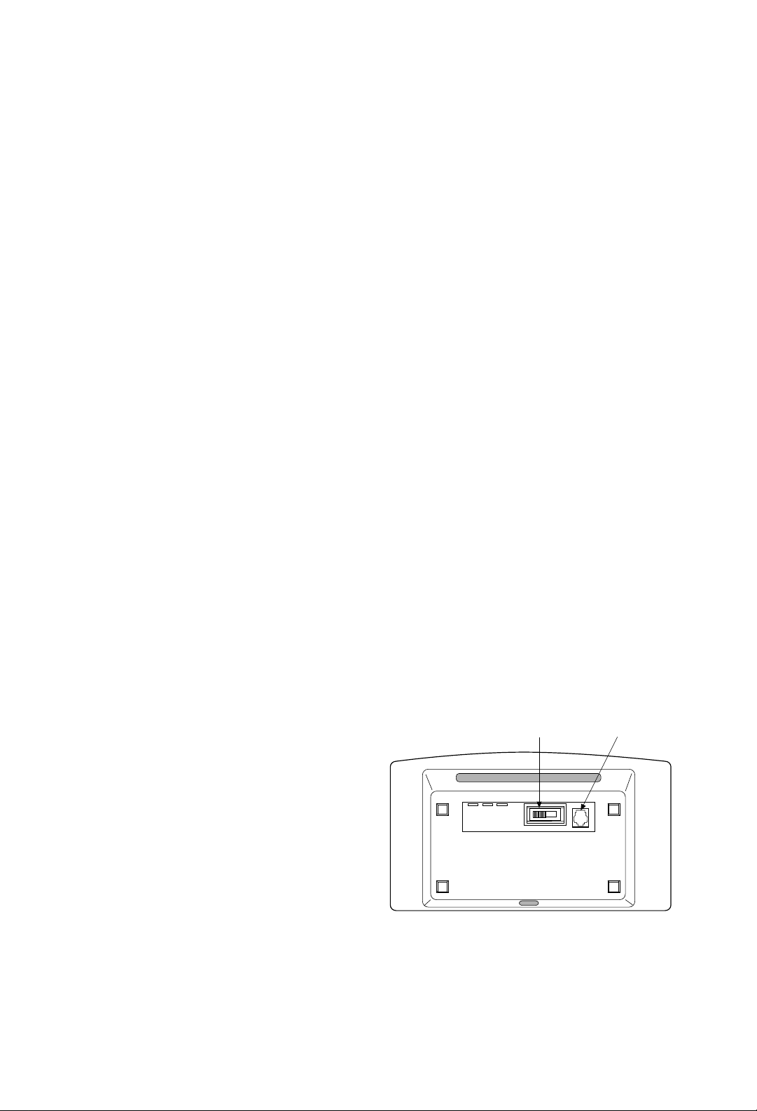
1.3 Getting Started
The STC-1 is powered-up by touching any area of the
display. If the STC-1 does not respond, make sure the
switch on the bottom of the unit is not at the OFF
position. Slide the switch to the
ON position as
indicated by the arrow.
On/Off Switch
RJ-11 Jack
Page 7
1.0
INTRODUCTION
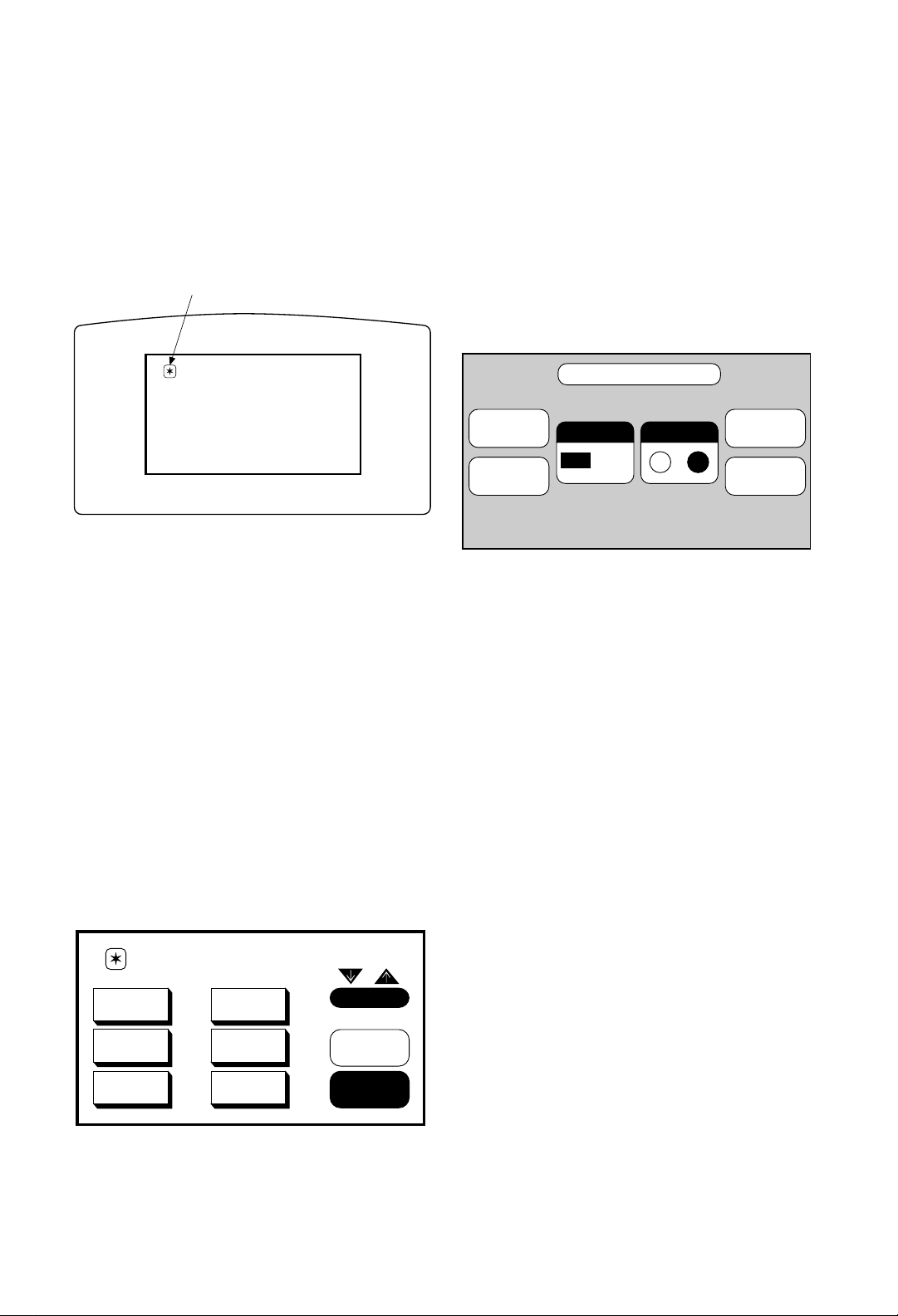
1.5 The Special Functions Page
The Main Menu page contains a unique icon in its
upper left corner. Selecting this icon displays the
Special Functions page. This page is used for invoking
several built-in functions and entering the Program
Mode.
The built-in functions include:
PROGRAM MODE
Press this button to enter the programming mode of the
STC-1. If the Access Lock Out is
ON, the access
passcode must be entered or the unit will remain on the
Special Functions page, preventing unauthorized
individuals from reprogramming the unit.
BEEPER ON/OFF
These two buttons turn the audible beep on and off.
BACKLIGHT LEVEL
This button may be pressed to cycle the backlight level
from High to Medium to Low.
POWER MONITOR
The charging icon will flash on the bottom of the special
functions page when the unit is actually charging. This
icon will continue to flash until the power supply is
disconnected from the unit. When recharging, use only
the power supply (DC, 9V, 1.4A, pin negative) that is
supplied with the unit. The recharging time will take
between eight and twelve hours, depending on the
battery status prior to recharging.
5
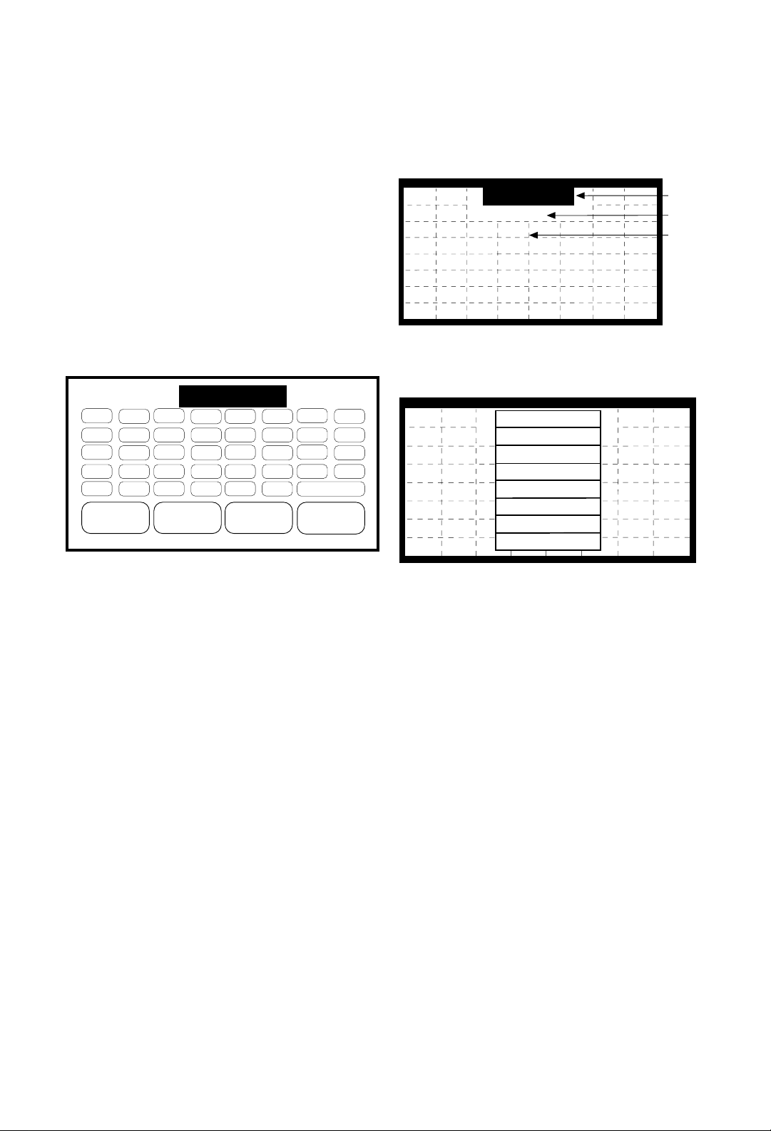
Upon power-up, the STC-1 will display its Main Menu
page, which is blank by default, awaiting programming.
The default initial screen is shown below.
1.4 The Touch Screen Display
The STC-1 touch screen display is organized as a series
of pages. A page consists of all the information
displayed on the screen at one time. Normally each page
contains objects (buttons, text, and symbols) that are
related in some way. For instance, they may all display
information necessary for controlling a particular VCR.
By default the STC-1 has one Main Menu page–all other
pages are considered submenus. Any page can contain
a button that will display any other page when selected.
Normally the Main Menu page is used to display the
names of the submenus (e.g., the equipment being
controlled). The submenus may consist of one or more
pages. The STC-1 will support 22 pages plus the Main
Menu page, in addition to the unit’s programming
screens. A representation of a programmed Main Menu
page is shown below.
Special Functions Page Icon
MAIN MENU
VOLUME
MUTE
TURN ON
SYSTEM
TURN OFF
SYSTEM
LASER
DISC
LIGHTS
SECURITY
MAIN MENU
TV
VCR
COMPACT
DISC
SPECIAL FUNCTIONS
PROGRAM
MODE
BACKLIGHT
LEVEL
BEEPER
ON
OFF
CONTRAST
–
POWER
OFF
+
EXIT
Page 8
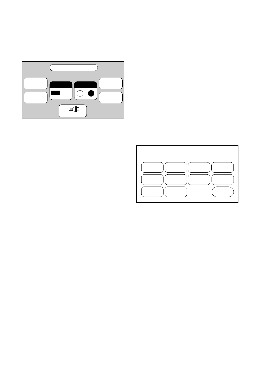
POWER OFF
This button invokes the Stand-By mode.
CONTRAST UP/DOWN
These two buttons adjust the LCD contrast.
EXIT
Pressing the EXIT button will return you to the Main
Menu page.
1.6 Battery Recharging
and Control
The following recommendations will assure best battery
performance:
1.Operate the unit until you receive a Low Battery
warning. At that point, you will have approximately 10
minutes of run time remaining before the unit shuts
down.
2.Recharge the STC-1 for at least 10 hours.
3.After recharging is complete, disconnect the AC
adapter.
6
1.7 Programming the STC-1
Programming the STC-1 involves a three-step process:
1.Drawing and linking all of the pages that will become
the user interface.
2.Teaching the STC-1 the infrared commands from
other remote controls.
3.Creating macros.
All programming steps are initiated from the Program
Options page. This page is displayed by pressing the
PROGRAM MODE button on the Special Functions
page.
There are 10 functions available on the Program Options
page:
CREATE PAGE
This function is used to create a new page.
EDIT PAGE
This function is used to place buttons, text, and symbols
on a page.
DELETE PAGE
This function is used to delete an existing page.
COMPUTER LINK
This function toggles the PC communication link ON
and OFF and is used to back up the STC-1
programming with a personal computer. It can also be
used to load previously developed pages and IR codes.
The interface program, available from JBL, requires a
PC running Windows 3.1 and a serial port.
EDIT MACRO
This function is used to create, edit, and delete macros.
EDIT IR
This function is used to learn, edit, and delete infrared
commands.
SPECIAL FUNCTIONS
PROGRAM
MODE
BACKLIGHT
LEVEL
BEEPER
ON
CONTRAST
OFF
CHARGING
–
POWER
OFF
+
EXIT
PROGRAM OPTIONS
CREATE
PAGE
EDIT
PAGE
DELETE
PAGE
COMPUTER
LINK
EDIT
MACRO
CHARGE
CONTROL
EDIT
IR
CLEAR
ALL
ACCESS
OPTIONS
TIMER
SETTINGS
EXIT
Page 9
1.0
INTRODUCTION
1.8 Setting the Access Options
To limit access to the PROGRAM MODE button on the
special functions page, select the
ACCESS OPTIONS
button from the Program Options page. The STC-1 will
display the
CHANGE PASSCODE button; and the
LOCK OUT OFF and ON buttons.
Either select the desired option or press the
EXIT button
to cancel the operation. If the
CHANGE PASSCODE
button is selected, the STC-1 will display a keypad and
prompt you to enter a passcode. The passcode can be
any number, from one to four digits in length. After
entering a passcode, press the
ENTER button on the
touch screen.
Do not forget the passcode. You will
be prompted to enter the passcode again for verification.
This passcode must now be used to enter the
PROGRAM MODE on the Special Functions page if
the
LOCK OUT button is ON. You can enable or disable
the need for a passcode by selecting the
LOCK OUT
ON
or OFF buttons.
▼ CAUTION: Always use a one- to four-digit
passcode. Never press the ENTER button
(i.e., no passcode) when the unit prompts
you for the passcode.
7
ACCESS OPTIONS
This function is used to program a passcode into the
unit and to enable or disable the
PROGRAM MODE
button from the Program Options page. This allows you
to limit program mode access to only those people that
know the passcode.
TIMER SETTINGS
This function is used to set the STC-1’s stand-by and
power-down timers. The stand-by timer defines the
length of time the display remains on after the last time a
button was pressed. During Stand-By mode, the STC-1’s
circuits are still energized, but the STC-1 uses much
less battery power than when it’s running. The powerdown timer defines the length of time the STC-1’s
circuits remain energized after entering the Stand-By
mode. During power-down, the STC-1 uses virtually no
battery power.
CLEAR ALL
▼ WARNING: The Clear All operation will wipe out all
pages and IR commands in the STC-1.
If you wish to start with a “clean slate,” the Clear All
option will remove all the buttons, pages, and
commands from the STC-1’s memory. To ensure that
accidental erasure doesn’t occur, you must enter the
security code before the memory will be erased.
If you inadvertently press the
CLEAR ALL button,
simply press the
ENTER button on the touch screen
without entering the passcode
and you will be returned
to the Program Options page.
EXIT
This option is used to return to the Special Functions
page.
ACCESS OPTIONS
CHANGE
PASSCODE
LOCK OUT
OFF
ON
EXIT
Page 10
8
2.0
CREATING
AND EDITING
PAGES
This chapter describes in detail how to program the
STC-1.
2.1 Creating a Page
To create a page, all you have to do is give it a name. To
do so, select the
CREATE PAGE button from the
Program Options page. When the text editor is
displayed, enter a name of up to eight characters in
length. A representation of the Create Page keypad is
shown below.
Although the STC-1 allows you to give different pages
the same name, using unique names for each page is
recommended since these names are used by the PC
Interface to catalog a library of pages you have created.
For information on using the text editor, see the section
“Using the Text Editor” on page 10.
2.2 Editing a Page
The page editor is used to create the STC-1’s user
interface. Editing pages is a three step process:
1.Create a new page.
2.Place buttons, text, and symbols on the page.
3.Assign a page to at least one of the buttons on the
page you have created (i.e., Main Menu).
To begin editing a page, select the
EDIT PAGE button
from the Program Options page. The STC-1 will display
a list of page names that were previously created using
the
CREATE PAGE utility. Either select the desired page
or press the
EXIT button to cancel the operation. If a
page is selected, the STC-1 will display that page with a
drawing grid and a pull-down menu bar.
The menu bar displays the current function being
performed. To select a new function, display the menu
by touching the center of the menu bar.
The options available in this menu are:
COPY PAGE
Use the COPY PAGEfunction to copy a page button
layout. There may be some functions like Volume, Mute,
and Exit that you want to have on the same place on
every page. You may also find this useful to duplicate
the controls of transports (i.e., CD, laser disc, VCR, tape
deck, etc.). This function copies the page button layout
only. It does not copy IR codes, macros, or page titles. It
does, however, copy all page assignments that are
attached to the buttons. To copy a page:
1.Make a mental note of the page you would like to
copy.
2.On the Program Options page, press the
CREATE
PAGE
button, then name the new page.
3.Press the
EDIT PAGEbutton, select the page you just
created, and press
DRAW BUTTON (which pulls
down the edit menu). Press
COPY PAGEto select the
page you would like to copy. The display will list the
names of all the available pages; press the name of
the page you want to copy.
DRAW BUTTON
This function is used for locating and sizing buttons, as
well as for selecting styles and shapes.
VCR_
B
J
R
Z
8
C
K
S
1
9
< CURSOR
D
L
T
2
0
E
M
U
3
+
CURSOR >
F
N
V
4
–
G
O
W
5
MORE >>
ENTER
H
P
X
6
A
I
Q
Y
7
SPACE
DRAW BUTTON
Menu
Page Title Area
Drawing Grid
COPY PAGE
DRAW BUTTON
EDIT TEXT
ASSIGN PAGE
REMOVE PAGE
DELETE BUT
CANCEL
EXIT
Page 11

2.0
CREATING
AND EDITING
PAGES
9
Once a button has been placed on the page, its shape
can be changed. The list of available button shapes can
be displayed by touching the button while in the
DRAW
BUTTON
mode. When the list is displayed, either select
the desired shape or press
CANCEL to exit without
making a change. There are 10 different types of button
styles and shapes to choose from:
NORMAL
This is a rectangular shape.
RADIUS
This is a rectangular shape with mitered corners.
OBLONG
This shape is rounded on the left and right sides.
EDIT TEXT
This function is used for
placing text and symbols within
buttons. It is also used for
entering a page title.
ASSIGN PAGE
This function is used for linking pages together.
Assigning a page to a button will cause that page to be
displayed whenever the button is selected.
REMOVE PAGE
This function is used to remove a page assignment from
a button.
DELETE BUT.
This function is used to delete
a button from the page. Using
this function will also delete
any infrared commands or
macros associated with the
button.
CANCEL
This option is used to close the menu without changing
functions.
EXIT
This option is used to exit the page editor.
NOTE: The maximum number of buttons that can be
created is 500. If the total number of buttons on all
pages reaches 500, the STC-1 will display a “memory
full” message.
2.3 Placing Buttons on a Page
Locating, sizing, and aligning buttons on a page is very
easy. To draw buttons on a page, select
DRAW
BUTTON
from the pull-down menu while in the Edit
Page mode.
All buttons are created by touching the
drawing grid where the button is to be
located, first by touching the upper left
corner, then by touching the lower right corner. Any
button size from 1x1 to 4x4 grid boxes can be created.
Because all buttons fall within the grid pattern, they are
automatically aligned.
DRAW BUTTON
DRAW BUTTON
Touch the UPPER
LEFT corner of the
button location first
Touch the LOWER
RIGHT corner of the
button to define the size
Radius
Button
DRAW BUTTON
Page 12

10
3D
This is a three-dimensional rectangular shape.
REVERSE
This option will reverse the dark and light areas of a
button.
TEXT BOX
This option is used when the button’s only function is to
display text. A text box will not respond when touched.
LT ARROW
This is a triangular shape pointing to the left.
RT ARROW
This is a triangular shape pointing to the right.
UP ARROW
This is a triangular shape pointing upward.
DN ARROW
This is a triangular shape pointing downward.
NO BORD.
This option will remove the button border. Only the text
within the button will be displayed. This type of button
will not respond when touched.
NOTE: Not all button shapes are available for every
button size. If a button shape is not available for a
particular button size, it will not be displayed in the list.
For example, the arrow buttons will only appear for 1x1
and 1x2 vertical button sizes.
2.4 Using the Text Editor
The text editor is used to place text and symbols on a
page. Text can be placed both within buttons and within
the page title area. To begin placing text on a page,
select
EDIT TEXT from the pull-down menu while in the
Edit Page mode. Now press either the button
that you want to place text into or the page title
area. (To access the page title area, press the
space directly under the
EDIT TEXT menu bar.) This
displays the text editor.
The darkened area at the top of the page represents the
amount of space available in the selected button for text.
The size of this space depends upon the size of the
button. Two darkened areas side by side indicates that
two lines of text can be entered.
As text is entered from the touch panel, the characters
are displayed in the darkened area. If two lines of text are
available, pressing the
ENTER button once will move
the cursor to the area for the second line. You can also
use the cursor keys to jump back and forth between the
two. Pressing the
ENTER button again will exit the text
editor and place the text inside the selected button or
page title area. If only one line of text is available for the
selected button, the
ENTER button needs to be pressed
only once. All text is automatically centered within the
selected button or page title area.
3D
Button
DRAW BUTTON
A B
I
J
Q
R
Z
Y
8
7
SPACE
D
C
K
L
T
S
1
2
0
9
E
MVN
U
3
+
CURSOR > ENTER< CURSOR
F
4
–
G
WOX
5
MORE >>
H
P
6
Text
Space
Available
Page 13

2.0
CREATING
AND EDITING
PAGES
11
Be sure to create an EXIT or RETURN button that
returns you to the Main Menu. This is ver
y important;
otherwise you will create a “dead end” and have no
recourse but to turn off the unit with the switch on the
bottom. If you do reset the unit in this fashion, when you
turn the STC-1 back on you will be returned to the Main
Menu page, but none of the programming will be lost.
To assign a page to a button, select
ASSIGN
PAGE
from the pull-down menu while in the Edit
Page mode. Now select the button for the page
assignment. The STC-1 will display a list of page
names, including the Main Menu page, from which you
can select. Either select the desired page or press
EXIT
to cancel the operation. All buttons that have a page
assignment will show a dashed box around them while
in the Assign Page mode.
2.6 Removing a Page Assignment
from a Button
To remove a page assignment from a button, select
REMOVE PAGE from the pull-down menu while in the
Edit Page mode. Now select the button with the page
assignment to be removed. The button should no longer
have a dashed border around it, indicating that the page
assignment has been removed.
2.7 Deleting a Button from a Page
To delete a button from a page, select DELETE BUT.
from the pull-down menu while in the Edit Page mode.
Now select the button to be deleted. Note that this
operation also deletes any infrared commands or macros
that are assigned to the button.
Additional symbols can be entered by pressing the
MORE >> button. This will display a window
containing the additional symbols. Either select a
symbol to be entered or press the
CANCEL button to
close the window. Note that most of these symbols can
not be displayed on the page title area.
If this is the first time you are naming a button, as you
start to type in button name, the
AUTOTEXT feature of the STC-1
will try to guess what you are
writing. You may only need to type
in one or two letters. If you do not wish to use what the
STC-1 is suggesting, simply keep typing. The database
the STC-1 uses for this is pre-defined; it will not learn
any new words you enter.
NOTE: There are no selectable character fonts. A small
font is automatically assigned to all button text, and a
large font is automatically assigned to the page title text.
2.5 Assigning a Page to a Button
After pages have been created and edited, they must be
linked. Linking pages allows you to navigate through all
of the individual pages that have been created. This is
the electronic equivalent of turning a page in a book. By
assigning a page to a button, the assigned page will be
displayed whenever the button is pressed.
7
Y
8
Z
CURSOR > ENTER< CURSOR
SPACE
Q
I
R
J
A
B
5 6
WOX
P
G
H
MORE >>
*
/
<
.
,
>
-
&
"
#
➔
➔
CANCEL
Text
Space
Available
Button with Page
Assigned as shown
in Edit Page Mode
ASSIGN PAGE
Page 14

The STC-1 learns and reproduces the infrared
commands of other remote controls. Each of these
infrared commands must be programmed into the
STC-1. This is done by using the original remote
control (the donor) from a piece of equipment to teach
its commands to the STC-1. There are four steps to this
learning process:
1.Aligning the donor remote with the STC-1.
2.Teaching the STC-1 an infrared command.
3.Testing the learned command.
4.Editing the learned command.
To begin performing these steps, select the
EDIT IR
from the Program Options page. The STC-1 will display
a list of page names to select from. Either select the
desired page or press the
EXIT button to cancel the
operation. If a page is selected, the STC-1 will display
that page along with the
ALIGN IR template in the
center, as shown below.
To select a new function, press anywhere on the screen,
then display the menu by touching the top of the menu
bar (where it says
LEARN IR).
12
3.0
IR EDITOR
3.1 Menu Options
The options available in this menu are:
LEARN IR
This function is used for aligning the donor and
teaching the STC-1 the infrared commands from the
donor.
TEST IR
This function is used to verify that
a command works properly.
EDIT IR
This function is used to modify a command if necessary.
See “Hints for Learning IR Codes” on page 19.
ALIGN IR
This function is used to properly align the donor with
the STC-1‘s learning window.
DELETE IR
This function is used to delete an existing command.
CANCEL
This option is used to close the menu without changing
functions.
EXIT
This option is used to exit the infrared editor.
LEARN IR
ALIGN IR
SIGNAL
OVERLOAD
Edit IR Menu Bar
LEARN IR
TEST IR
EDIT IR
ALIGN IR
DELETE IR
CANCEL
EXIT
Page 15

3.0
IR EDITOR
To properly align a donor remote control with the STC-1,
first make sure the donor remote is at the same height as
the learning window. It may be necessary to place the
donor remote control on a higher surface than the
STC-1. Now press any key on the donor remote control,
moving the control back and forth in front of the learning
window. The donor remote control is located at the
proper distance from the STC-1 when the
SIGNAL box
is on (darkened) and the
OVERLOAD box is off (clear).
If neither box is on, the STC-1 is not detecting any
infrared signal.
If the
SIGNAL box will not turn
on without turning on the
OVERLOAD box, you should
ignore the overload indicator. This will only happen for
certain types of infrared commands. These special types
of commands can usually be learned from any distance
as long as the
SIGNAL box is on.
Touching the display anywhere will cancel the Align IR
function.
13
3.2 Aligning a Remote Control
To ensure that a valid signal is being received, all donor
remote controls should be properly aligned with the
STC-1‘s learning window. This is the small window
located on the front of the unit.
The STC-1 has an
ALIGN IR function to help determine
the correct position in front of the learning window. This
function is invoked upon entering the Edit IR mode or by
selecting
ALIGN IR from the pull-down menu while in
the Edit IR mode.
Transmit IR
LEARN IR
ALIGN IR
SIGNAL
OVERLOAD
Edit IR Menu Bar
Window
IR Learning Window
Page 16

3.3 Sending Infrared Commands
to the STC-1
Once a donor remote control is properly aligned, the
STC-1 is ready to start receiving and storing the infrared
commands. First, make sure the STC-1 is in the Edit IR
mode and Learn IR is selected from the menu.
Next, select a button on the STC-1 that you wish to
assign a command to. After pressing the button, the
STC-1 will display a
READY message. Now press the
key on the donor remote control that transmits the
command that you want the STC-1 to learn. Continue to
hold the key down until the STC-1 displays O.K.
After the command has been processed and stored, the
STC-1 will display
LEARNED. If an error message is
displayed, realign the donor remote control and try
again. All buttons that have an infrared command
assigned to them will have a dashed border displayed
around them while in the Edit IR mode.
3.4 Testing Infrared Commands
After a command has been learned by the STC-1, you
should test it to make sure it behaves properly. This can
be done by selecting
TEST IR from the pull-down menu
while in the Edit IR mode. To test a command, point the
STC-1 at the equipment to be controlled and press the
appropriate button on the display. If the command does
not work properly, it may need to be edited or re-learned.
14
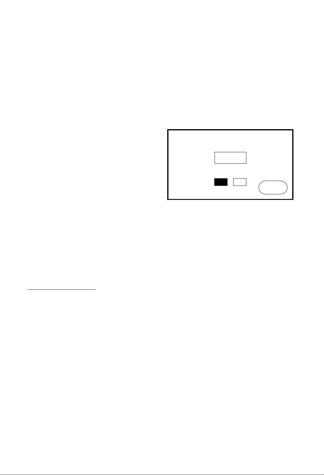
3.5 Editing Infrared Commands
Most infrared codes will transmit continuously as long
as the remote control key is held down. This means that
either the entire code or some part of it is being repeated
over and over. Some infrared receivers need a command
to be repeated a certain number of times to work
properly. This may be anywhere from two to twenty
times. Also, some infrared receivers may not work
properly if the command is repeated at all. This is why
the STC-1 allows you to adjust the number of command
repeat times and to enable or disable continuous
transmission.
To edit an infrared command, select
EDIT IR from the
pull-down menu while in the Edit IR mode. Now select a
button with an infrared command that you want to edit.
This will display the Edit IR page.
The repeat times can be adjusted from 0 to 25, and the
SUSTAIN function can be turned on or off. If the
SUSTAIN function is turned off, the command will be
transmitted the selected number of repeat times. If
SUSTAIN is turned on, the command will be
transmitted for as long as the button is pressed plus
the
number of repeat times. The default setting for most
commands is
SUSTAIN ONand MIN. REPEAT = 3.
Even if a command works properly, increasing the
number of repeat times may be necessary if the
command is to be used in a macro. Since macro
commands are not sustained while a button is pressed,
they may need to automatically repeat more times to be
recognized.
EDIT IR
VOLUME
RECORD
VCR
PLAY
>
POWER
PAUSE
STOP
SEARCH
SEARCH
MAIN
MENU
MUTE
FAST FWD
>>
REWIND
<<
Button with Infrared Command
assigned as shown in Edit IR Mode
EDIT IR
MIN. REPEAT:
SUSTAIN:
03
OFF ON
Page 17

4.0
MACRO
EDITOR
15
4.1 Menu Options
The options available in this menu are:
EDIT MACRO
This function is used for inserting infrared commands
and time delays.
TEST MACRO
This function is used to verify that a macro executes
properly.
DELETE MACRO
This function is used to delete an existing macro.
CANCEL
This option is used to close the menu without changing
functions.
EXIT
This option is used to exit the macro editor and return to
the Program Options page.
4.2 Editing a Macro
After selecting a button to assign a macro to, the STC-1
will display the
MACRO EDITOR page. This page
displays the 24 possible steps in the macro along with a
pull-down menu bar.
The menu bar displays the current function being
performed. To select a new function, display the menu
by touching the center of the menu bar. The options
available in this menu are:
COMMAND
This function is used to insert an infrared command into
a macro.
A macro is a series of infrared commands that is
executed by pressing a single button. For example, you
could create a macro called
“MOVIE” that turns on the
TV, selects the VCR input, turns on the VCR, dims the
lights, and starts the movie. Macros are one of the
simplest ways to make a complicated system easy to
use.
Creating a macro on the STC-1 is a three step process:
1.Select the button that will execute the macro.
2.Edit the macro. This step involves selecting the
commands that the macro will execute and inserting
any necessary time delays.
3.Test the macro to make sure it performs as expected.
To begin creating a macro, select the
EDIT MACRO
button from the Program Options page. The STC-1 will
display a list of available page names. Either select the
desired page or press the
EXIT button to cancel the
operation. If a page is selected, the STC-1 will display
that page along with a pull-down menu bar.
The menu bar displays the current function being
performed. To select a new function, display the menu
by touching the center of the menu bar.
4.0
MACRO
EDITOR
EDIT MACRO
VOLUME
RECORD
VCR
PLAY
>
POWER
PAUSE
STOP
SEARCH
SEARCH
MAIN
MENU
MUTE
FAST FWD
>>
REWIND
<<
Macro Editor
Menu Bar
Page 18

TIME DELAY
This function is used to insert a time delay into a macro.
INSERT BEFORE
This function is used to insert a step in front of another
step. It is used when a command or time delay must be
placed before an existing step.
REMOVE STEP
This function is used to remove a command or time
delay from a macro.
CANCEL
This option is used to close the menu without changing
functions.
EXIT
This option is used to exit the macro editor page and
return you to the main
EDIT MACRO page.
4.3 Inserting an Infrared
Command
First, select the COMMAND option from the Macro
Editor menu. Next, select the step position where you
want the command inserted. This will cause the STC-1
to display a list of page names. Either select the page
that contains the infrared command to be inserted or
select the
EXIT button to cancel the operation. If a page
is selected, the STC-1 will display that page. Now select
the button that contains the infrared command to be
inserted. If a valid button was selected, the STC-1 will
return to the macro editor page with the command
inserted in the macro step.
The name that appears in that macro step is taken from
the first line of the button name and can be up to eight
characters long. If there is no IR code assigned to the
button, no command will be learned, and the step button
will still show the step number.
16
4.4 Inserting a Time Delay
Some commands in a macro may need a short time
delay between them. There are basically two types of
situations in which this might be necessary:
1.If one of the commands in a macro turns a device on
(e.g., the power command for a TV), the device may
need several seconds to “warm up” before it can
receive another command.
2.If the macro transmits back-to-back commands to the
same device, a very short time delay may be
necessary to help the device recognize that there is
more than one command.
To insert a time delay into a macro, select the
TIME
DELAY
option from the Macro Editor menu. Next, select
the step position where you want the time delay inserted.
This will cause the STC-1 to display a numeric keypad.
Use the numeric keypad to enter the desired time delay
in seconds. The longest time delay that can be entered is
9.9 seconds. If a time delay longer than 9.9 seconds is
needed, you can insert multiple time delays in a row.
NOTE: The maximum number of macros that can be
created is 100. If the total number of macros reaches
100, the STC-1 will display a “memory full” message.
COMMAND
TV PWR
STEP 2
STEP 3
STEP 4
STEP 5
STEP 6
STEP 7
STEP 8
STEP 9
STEP 10
STEP 11
STEP 12
STEP 13
STEP 14
STEP 15
STEP 16
STEP 17
STEP 18
STEP 19
STEP 20
STEP 21
STEP 22
STEP 23
STEP 24
MACRO EDITOR
COMMAND
TV PWR
VCR PWR
0.3 SEC
STEP 4
STEP 5
STEP 6
STEP 7
STEP 8
STEP 9
STEP 10
STEP 11
STEP 12
STEP 13
STEP 14
STEP 15
STEP 16
STEP 17
STEP 18
STEP 19
STEP 20
STEP 21
STEP 22
STEP 23
STEP 24
MACRO EDITOR
Page 19

4.0
MACRO
EDITOR
.
17
4.5 Macro Hints
You cannot string macros together by calling up another
macro as a step within the macro you are editing.
A button can contain a macro, an IR command, and a
page assignment. When a button is pressed, the STC-1
will first send the IR command, then run the macro, and
finally go to the page assigned. Remember that you
cannot assign a button to a macro unless there is a
“learned” IR command associated with it. If you would
like to call up another page at the end of a macro, go to
the Edit Page mode and assign a page to the same
button that runs the macro. The assigned page will be
displayed after the macro has been completed.
Page 20

There are two types of infrared codes that are commonly
used for consumer electronics products:
Frequency
Modulated and Pulsed.
5.1 Frequency Modulation
This type of transmission modulates the IR energy at a
fixed carrier frequency. The vast majority of consumer
electronics remote controls use a carrier frequency
around 40 kHz, although the carrier can range from 20
kHz to 500 kHz or higher. While the STC-1 is rated to
handle carrier frequencies between 10 kHz and 110 kHz,
in practice it can learn some carrier frequencies outside
of this range.
The actual code consists of bursts of IR energy
modulated at the carrier frequency, separated by pauses.
The code is defined by the length of each burst and each
pause, as well as by the carrier frequency.
5.2 Pulsed IR Codes
This type of transmission does not use a carrier
frequency.
Pulsed codes are quite common in cable TV converter
boxes.
18
5.0
IR CODE
BASICS
5.3 How the STC-1 Learns
IR Commands
There are many different encoding schemes used for IR
codes. The burst and pause times have fixed lengths,
variable lengths, or some combination of the two. To
learn the code, the STC-1 “records” a sample of the
code in a manner similar to the way a tape recorder
records sound. Once a sample of the code has been
taken, it is analyzed to find any repeating patterns.
Some codes continuously repeat themselves for as long
as the button is pressed. Others send a code followed by
a “keep alive” pattern. Some codes don’t repeat at all.
Any of the above types of codes can also have some sort
of preamble in front of them. It is very important to
capture the preamble in this type of code. The IR
learning buffer of the STC-1 is large enough to
accommodate the preamble.
When a repeating pattern is found, extra repeats are
stripped off before the code is stored in memory. The
number of repeats is also stored so the code can be
reproduced accurately.
If the buffer was filled up during learning, it is assumed
that the pattern should be repeated for as long as the key
is pressed. This is common for commands such as
Volume, Balance, and Scan– functions that may need to
be continuously repeated. For these types of commands,
SUSTAIN is set ON as the Edit IR default. If the buffer is
not filled,
SUSTAIN is set OFF and the repeat pattern is
displayed as the
REPEAT TIMES.The default REPEAT
TIMES
for a code with SUSTAIN ON is two. This
means the repeating pattern will repeat three more times
after the pressed key is released. You can of course edit
this if needed, in the Edit IR command mode.
If the code uses a carrier frequency, that frequency is
also stored with the code.
Page 21

5.0
IR CODE
BASICS
19
5.4 Hints for Learning IR Codes
The OVERLOAD indicator in the ALIGN IR template is
only an approximation. The STC-1’s software makes its
“best guess” as to whether the remote control is too
close. If both the
OVERLOAD and the SIGNAL
indicators flash in tandem, regardless of distance, the
code is a pulsed type. The overload indicator will not
function properly with pulsed codes, so trial-and-error is
the only approach. Fortunately, pulsed codes are not as
sensitive to distance as modulated codes are. Generally,
it is better for the donor remote and the STC-1 to be too
close together than to be too far apart.
Always place the STC-1 and the donor remote control
on a flat surface. You may find it necessary to elevate the
donor with a book or similar object to align them
vertically. Once you have learned and tested a command
from a remote, try not to move it until you have learned
all the codes. If you do accidentally move either remote,
again select
ALIGN IR from the menu.
Some commands may take a long time to learn,
particularly sustain commands like Volume and Channel
Up/Down.
Many commands can be made more reliable if the
number of repeat times is increased. This is especially
true for commands assigned to buttons that are likely to
be briefly “tapped” or for commands that are part of a
macro. Increasing the number of repeat times increases
the probability of the command “getting through.” This
is essentially a trade-off between increased reliability
and an increase in the length of time required to transmit
a command. This can take a bit of fine tuning on
complicated macros.
Page 22

Keep in mind that the goal of the STC-1 is
simplification. Try not to put too many functions on each
page.
To program the STC-1 most efficiently, it is useful to
make basic templates of common types of controls, i.e.,
CD, Laser, VCR, transport controls, volume controls,
alpha-numeric keypads, etc. These templates can then
be copied and modified for specific devices and/or
installations. Keeping similar types of controls looking
and feeling similar on the STC-1 viewscreen will reduce
the learning curve.
Consider creating a basic page that contains only
Volume and Mute controls as well as an
EXIT button.
Assign the
EXIT button to the Main Menu page. You
can now copy this page as the basic template for all the
rest of your pages, since it is probably a good idea for
every page to have Volume and Mute functions.
The
EXIT button is critical; without it, the page would be
a dead end, since once entered, there is no way out
(other than to turn the unit off, then on, using the
ON/OFF switch on the bottom). Remember that
although the
COPY PAGE function will not copy the IR
commands, it will copy the Page Assignment; in this
way there will always be an
EXIT button on every page
derived from the basic page.
You can also copy this basic page to create a template
for other templates, such as Transport and Keypad
pages, which can be used for multiple products.
Try designing a Transport page; pages with
PLAY,
SCAN, SKIP, STOP
, and so on are useful for CD and
LD players, VCRs, etc. Not only will this speed up the
programming, but also it will make the unit simpler to
operate if all the machines look and feel the same.
20
6.0
PROGRAMMING
HINTS
A Keypad page will also have many applications for TVs,
Cable boxes, disc players, and so on.
You may also find it useful to create a hidden page.i. that
will not be seen by the end user. This page will contain
IR codes needed for macros but not needed for general
operation. When you program these types of buttons,
make sure to label the buttons in a way that will make
sense when you see its abbreviated name on the Macro
Step. The reason for this is that the Macro Step will use
the first line of text on the button, up to eight characters
long. For example, on the basic component pages, there
will often be a button for power. If you write a macro that
powers on several components, in the Macro Editor all
of the steps for this will say
POWER; this may be
confusing should you need to edit the macro. If you
duplicate these power-on commands on another page
that the user does not see, you can label them more
completely: i.e.,
CDPOWER, LDPOWER,
TVPOWER,
etc.
The PC Interface program contains some basic
templates (keypads, transport controls, etc.) that can be
downloaded and modified. You can also build your own
library of pages to be downloaded the next time you use
the same product. The interface library will save the
page graphics and IR codes.
VOLUME
PAUSE
PWR
MAIN
MENU
MUTE
PLAY
>
MORE
CONTROLS
LOAD/EJECT
SCAN SCAN
SKIP
SKIP
LIGHT 3
TUNR PWR
CD PLAY
LD PLAY
VCR PWR
DIM LITE
BRITE LT
HIDDEN PAGE
VCR PWR
TV PWR
CP-3 PWR
LIGHT 1
LIGHT 2
Page 23

6.0
PROGRAMMING
HINTS
21
6.1 Summary: Creating Pages
Page 24

7.0
TROUBLESHOOTING
Display is dim or unreadable.
Try adjusting the LCD contrast on the Special Functions
page. By nature, the contrast of an LCD varies with
temperature. This can be from external variations or
internal ones (battery charging). If the unit is cold, it
may take a couple of hours to reach room temperature
and for the LCD to stabilize.
Unit does not respond at all.
Check the ON/OFF switch on the bottom of the unit.
Also try switching the unit off for a few seconds before
turning it back on. If the unit still doesn’t respond, leave
the AC adapter connected for a few hours and try again.
SIGNAL and OVERLOAD indicators flash,
regardless of distance.
The donor remote control is a pulsed type. Ignore the
indicators, place the donor remote 6-8” from the unit,
and learn and test a command. See “Hints for Learning
IR Codes“ on page 1.
MACRO EDIT won’t learn some commands.
You can only insert a button with a valid IR command as
a macro step. If you attempt to insert any other type of
button (a button that represents another Macro or Page
Assignment), the STC-1 will double-beep (if the audible
beep option is turned on) and return you to the Macro
Editor page with the step unassigned. See “Editing a
Macro” on page 24.
You’re stuck.
If you create a page without an exit, and if you get to that
page when you are operating the STC-1, you will need
to reset the STC-1 by turning it off, then on, using the
ON/OFF switch on the bottom of the unit. You will return
to the Main Menu page, and none of the programming
will be lost.
22
7.0
TROUBLESHOOTING
Learned IR Commands don’t work.
Although the STC-1 has very flexible learning
capabilities, some devices are outside its capabilities.
The normal range of IR carrier frequencies that the
STC-1 can handle is between 10 kHz and 110 kHz.
Some companies use modulation frequencies well
outside this range. Many B&O remote controls, for
example, modulate at around 455 kHz. While the
LEARN IR indicator will show O.K., LEARNED, and
the transmit LED indicator in the front IR window will
flash, the IR receive indictor on the devices whose
remote control you are attempting to learn might not
flash. Remote controls operating at these very high
frequencies cannot be learned by the STC-1.
7.1 Contacting JBL
You can contact JBL at the following address:
JBL Consumer Products
80 Crossways Park West
Woodbury, NY 11797
TEL (516) 496-3400
Page 25

8.0
SPECIFICATIONS
23
8.0
SPECIFICATIONS
Power: Six (6) volt Ni-Cad Battery Pack
Infrared Control Range: Thirty (30) Feet (9.0m) @ 60 Degrees
Infrared Carrier Frequency Range: 20kHz–111kHz
Display: 256 x 128 STN (Blue on Paper White)
Backlight: Dual CFL
Power Consumption: 1000 mA Maximum* (Run Mode)
175 mA Maximum (Stand-by Mode)
170 mA Maximum (Powerdown Mode)
Nominal Run Time on Full Charge: 2.5 hours*
Maximum Number of Buttons: 500
Maximum Number of User-Defined Pages: 23
Maximum Number of User-Defined Macros: 100
Maximum Number of Steps per Macro: 24
Total System Memory: 128K Bytes
Communications: PC Interface Available
Dimensions: 9" x 5.3" x 3.5" (LxWxH)
Weight: 1.9 lbs.
* Medium Backlight Level
All specifications subject to change without notice.
Page 26

9.0
APPENDIX A:
SCREEN TEMPLATES
You can copy and use the templates below as an aid
when planning and designing button and page layouts.
Use the templates to sketch pages before actually
programming them into the STC-1.
USE THE AREA BELOW FOR NOTES
24
9.0
APPENDIX A:
SCREEN TEMPLATES
DRAW BUTTON
Page 27

10.0
INDEX
25
10.0
INDEX
A
ACCESS OPTIONS button, 7
ALIGN IR template, 12
Aligning a remote control, 13
AUTOTEXT feature in text editor, 11
B
BACKLIGHT LEVEL, 5
B&O remote controls
problems with, 22
Battery
charging, 6
run time between charges, 4
BEEPER ON/OFF button, 5
Built-in functions, 5
Buttons
ACCESS OPTIONS, 7
assigning pages to, 8, 9, 11
BEEPER ON/OFF, 5
CHANGE PASSCODE, 7
CLEAR ALL, 7
COMPUTER LINK, 6
CONTRAST UP/DOWN, 6
CREATE PAGE, 6, 8
DELETE PAGE, 6
deleting, 11
drawing, 6, 8
EDIT IR, 6, 12, 14
EDIT MACRO, 6, 15
EDIT PAGE, 6, 8
EXIT, 6, 7, 9
LOCK OUT ON/OFF, 7
maximum number of, 9
placement on page, 9
POWER OFF, 6
PROGRAM MODE, 5
removing page assignments from, 11
Special Functions icon, 5
styles and shapes of, 9, 10
text, space available for, 10, 11
TIMER SETTINGS, 7
C
Carrier frequency range, 18
CHANGE PASSCODE button, 7
CHARGING, 6
CLEAR ALL button, 7
COMPUTER LINK button, 6
CONTRAST UP/DOWN button, 6
Control range, 23
Controller
care of, 3
CREATE PAGE button, 6, 8
Creating a page, 8
D
DELETE PAGE button, 6
E
Edit IR, 6, 12, 14
menu options, 12
EDIT IR button, 6, 12, 14
EDIT MACRO button, 6, 15
EDIT PAGE button, 6, 8
Editing a macro, menu options, 12
Editing a page, 6, 8
menu options, 8, 9
EXIT button, 6, 7, 9
importance of, 11
omitting and getting stuck, 22
F
Features, STC-1, 4
Frequency modulation, 18
FULL CHARGE, 6
Page 28

I
Infrared codes, types of, 18
Infrared commands
editing, 14
hints for learning, 19, 22
inserting in macros, 16
learning process, 19
problems with, 22
programming, 16, 20
sending to the STC-1, 18
testing, 12, 14
Initial screen, 5
IR (infrared) Editor, 12
IR Code Basics, 18
IR Learning Window, 13
J
JBL, Inc., contacting, 22
L
LOCK OUT ON/OFF button, 7
LOW BATTERY warning, 6
M
Macro Editor, 15, 16
Macros
calling pages from, 16
creating, 15
deleting, 15
editing, 15, 16
hints, 17
infrared commands in, 16
maximum number of, 16
refusing to learn commands, 22
testing, 15
time delays in, 16
Main Menu page, 5
Memory, size of, 23
26
O
On/Off switch
location of, 4
OVERLOAD box, 13, 19
flashing regardless of distance, 19, 22
P
page title, 10
Pages
assigning to buttons, 9
calling from macros, 20
copying, 8
creating, 8, 21
deleting buttons from, 11
editing, 8
hidden, 20
linking, 11
MACRO EDITOR, 15
Main Menu, 5
number of, 5, 23
placing buttons on, 9
removing assignments from buttons, 11
Special Functions, 5
unique names for, 8
Passcode
and CLEAR ALL button, 7
caution about, 7
changing, 7
PC Interface Program, 4, 6, 20
Personal computer, link to, 4
POWER OFF button, 6
Power Monitor Feature, 4, 5
PROGRAM MODE button, 6
Programming the STC-1, 6
infrared commands, 12
programming hints, 20
Pulsed IR codes, 18
Page 29

27
10.0
INDEX
R
Remote control, aligning, 13
Repeat times, 14, 18
increasing, 14
Return button
importance of, 11
RJ-11 Jack
location of, 4
S
SIGNAL box, 13, 19
Special Functions Page Icon, 5
Specifications, 23
SUSTAIN function, 14, 18
T
Templates, 21, 24
in PC Interface program, 20
Text editor, 9, 10, 11
additional symbols, 11
AUTOTEXT feature, 11
Time delays, in macros,16
TIMER SETTINGS button, 6, 7
Touch Screen display, 4
adjusting contrast, 6
care of, 3, 4
problems with, 22
Transmit IR Window, 13
Troubleshooting, 22
W
Windows 3.1, 6
Page 30

28
11.0
JBL SYNTHESIS
LIMITED WARRANTY
The Synthesis products listed below are warranted for the
period stated from the date of original purchase. Amplifiers,
Equalizers, Signal Processing Package, Surround Processor,
and Touch Screen Remote—2 Year Warranty. This warranty
applies to non-commercial, residential use only.
Who is Protected by this Warranty?
Your JBL warranty protects the original owner and all
subsequent owners, so long as the original bill of sale is
presented when warranty service is required.
What is Covered by the JBL Warranty?
Your JBL warranty covers all defects in material and
workmanship with the following specified exceptions. These
are (1) damage caused by accident, unreasonable use or
neglect (including the lack of reasonable and necessary
maintenance); (2) damage caused by improper installation or
adjustment; (3) damage occurring during shipment (claims
must be presented to the carrier); (4) damage to or
deterioration of any accessory or decorative surface; (5)
damage resulting from failure to follow instructions contained
in your owner’s manual; (6) damage resulting from the
performance of repairs by someone other than an authorized
JBL warranty station; (7) any JBL unit on which the serial
number has been effaced, modified, or removed; (8) units
which have been altered or modified in design, appearance or
construction; (9) products sold on an "as-is" or final sale
basis. This warranty covers only the actual defects within the
product itself, and does not cover the costs of installation
or removal from a fixed installation, normal set-up or
adjustments, claims based on any misrepresentation by the
seller, or performance variations resulting from installation
related circumstances such as program source quality or
AC power.
How to Obtain Warranty Service.
If your JBL product ever needs service, we may direct you to
an Authorized JBL Warranty Station, or ask you to send your
unit to the factory for repair in which case we’ll also supply a
Service Return Authorization and complete shipping
instructions. If the product was purchased in a country other
than the USA, it is necessary to return the product to the
distributor or selling location in the same country. Either way,
you’ll need to present the original bill of sale to establish the
date of purchase. Please do not ship your JBL product to the
factory without our prior authorization. In the United States,
please call 1-800-336-4JBL for the location of the authorized
warranty station nearest you.
If service under this warranty is not necessary, but you
have questions regarding the installation or operation of
this unit, please contact your authorized JBL retailer or call
1-800-336-4JBL for further assistance.
11.0
JBL SYNTHESIS
LIMITED WARRANTY
Who Pays for What?
JBL will be happy to pay all labor and material expenses for
all repairs covered by this warranty. If necessary repairs are
not covered by this warranty, or if a unit is examined which is
not in need of repair, you will be charged for the repairs or the
examination.
Although you must pay any shipping charges incurred in
getting your JBL product to an Authorized Warranty Station or
to the factory, we will pay return shipping charges within the
United States if the repairs are covered by the warranty.
Please be sure to save the original shipping cartons because
a nominal charge will be made for additional cartons.
LIMITATION ON IMPLIED WARRANTIES.
IMPLIED WARRANTIES OF MERCHANTABILITY AND
FITNESS FOR PARTICULAR PURPOSE ARE LIMITED IN
DURATION TO THE LENGTH OF THIS WARRANTY, UNLESS
OTHERWISE PROVIDED BY STATE LAW.
EXCLUSION OF CERTAIN DAMAGES.
JBL'S LIABILITY IS LIMITED TO THE REPAIR OR
REPLACEMENT AT OUR OPTION, OF ANY DEFECTIVE
PRODUCT AND SHALL IN NO EVENT INCLUDE INCIDENTAL
OR CONSEQUENTIAL COMMERCIAL DAMAGES OF ANY KIND.
ANY REPLACEMENT UNITS OR PARTS MAY BE NEW OR
REBUILT. JBL RESERVES THE RIGHT TO REPLACE A
DISCONTINUED MODEL WITH A COMPARABLE MODEL.
SOME STATES DO NOT ALLOW LIMITATIONS ON
HOW LONG AN IMPLIED WARRANTY LASTS AND/OR
DO NOT ALLOW THE EXCLUSION OF INCIDENTAL OR
CONSEQUENTIAL DAMAGES, SO THE ABOVE LIMITATIONS
AND EXCLUSIONS MAY NOT APPLY TO YOU.
This warranty gives you specific legal rights, and you may
also have other rights which vary from state to state.
We sincerely thank you for your expression of confidence in
JBL products. This equipment has been painstakingly
assembled by highly trained craftspeople. It should give you
many years of musical enjoyment.
Page 31

Page 32

JBL Synthesis STC-1
Owner's Manual
©1995 Harman Consumer Group
JBL and Synthesis are registered trademarks of JBL Incorporated
All Rights Reserved
Design and digital production by Harman Consumer Group Design
and Production Center, Woodbury, NY
JBL Consumer Products, Inc.
80 Crossways Park West, Woodbury, NY 11797
(516) 496-3400
8500 Balboa Boulevard, Northridge, CA 91329
Part No. STC1OM895
Printed in USA
A Harman International Company
 Loading...