

Page 1
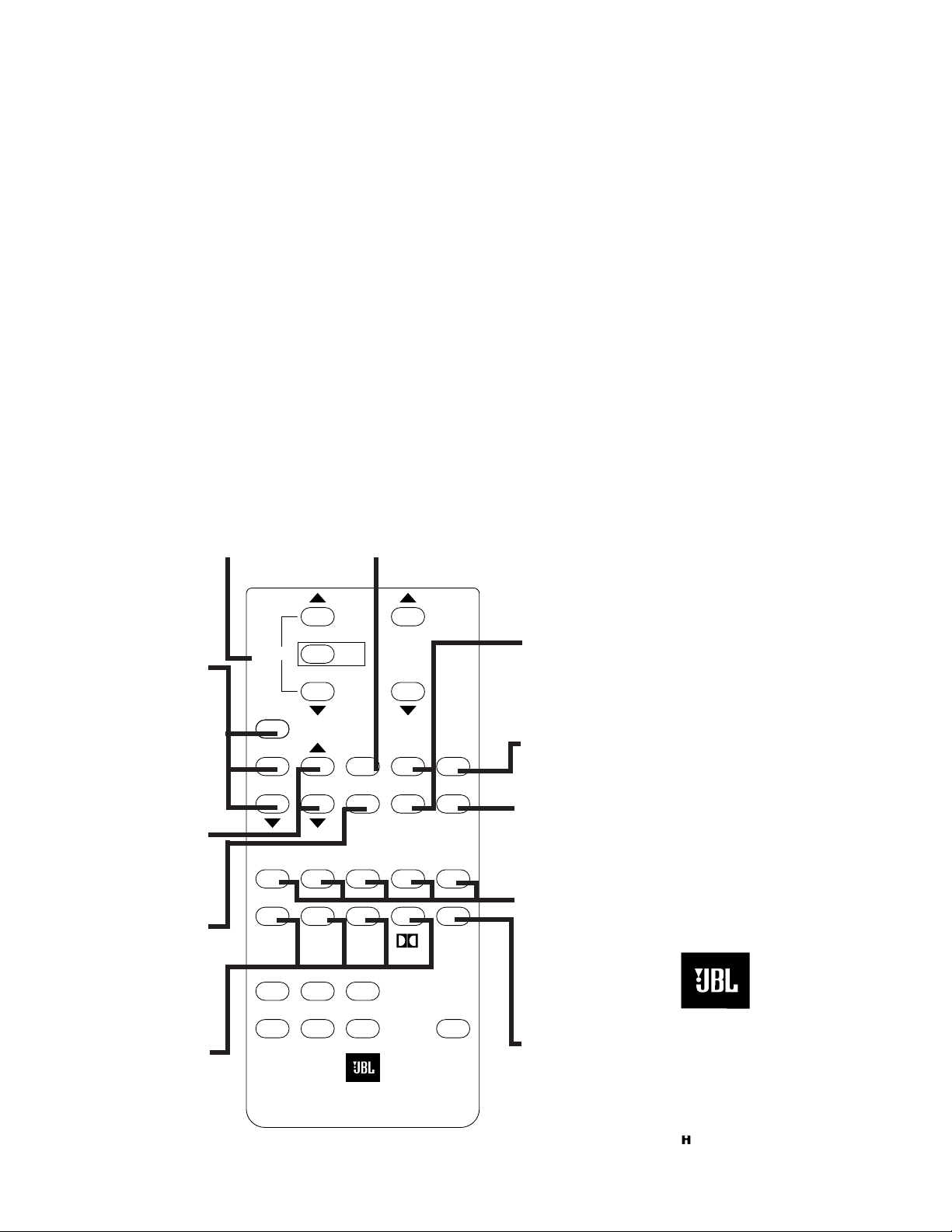
Delay
Bypass
Master
Volume
Ambience
Center On Mute
Center
Boost
Hi Freq
EQ
Rock Pop Jazz Hall 1 Hall 2
S-VID-1
VDP
S-VID-2CDVCR
Aux
Sib
Fil
Ref.
+
35 mm
Movie
THX
Power
-
SYNTHESIS
Center
70 mm
Movie
Mono
Enhance
Sound
Stage
Press AMBIENCE
UP to add more
volume to Ambient
Speakers. Press
AMBIENT DOWN to
have less. Press
REF to return to
pre-set levels
Press SOUND
STAGE to increase
Stereo Separation.
Press DOWN to
decrease Separation.
Press CENTER to
return to pre-set
levels
Press DELAY UP to
increase Ambient
Spaciousness.
Press DELAY
DOWN to decrease
Press BYPASS to
turn off Center and
Ambient Speakers
Cinema Surround
MODES: 70mm,
35mm, THX, Dolby
Press SIBILANCE
if dialogue is too
loud from Ambient
Speakers
Press CENTERON
to turn on Center
Speaker. Press
CENTER BOOST to
increase volume
from Center Speaker
Press MUTE to cut
off sound
Press HI FREQ EQ
if sound appears
too bright
Music Surround
MODES
Press MONO
ENHANCE to add
simulated stereo to
Monaural Sources
JBL SP MK II
Surround Processor
User's Manual
Quick-Start
ADVANCED
OPERATIONS
JBL Consumer Products,
Incorporated
240 Crossways Park West
Woodbury, NY 11797
8500 Balboa Boulevard
Northridge, CA 91329
800-645-7484
Part #: OMSPMKII M8/93
A Harman International Company
Page 2

SYNTHESIS
SURROUND
PROCESSOR
Model SP MK II
THX®Controller—
A/V Surround Processor
USER'S
MANUAL
®
SYNTHESIS
Page 3
TABLE OF CONTENTS
FOR PEOPLE WHO DON’T READ INSTRUCTION MANUALS ............................................................. 1
A STEP BY STEP “QUICK GUIDE” ....................................................................................................... 2
MOTION PICTURE SOUND: A BRIEF HISTORY ................................................................................... 3
THE GOAL OF LUCASFILM HOME THX®CINEMA .............................................................................. 4
PLANNING AND INSTALLATION GUIDE ............................................................................................. 5
SP MK II OVERVIEW ................................................................................................................ 6
SP MK II OPERATING PARAMETERS ...................................................................................... 7
LUCASFILM HOME THX CINEMA ........................................................................................... 9
PLANNING YOUR HOME SURROUND AUDIO SYSTEM ................................................................... 11
ELECTRONICS PLACEMENT & VIDEO REQUIREMENTS ..................................................... 12
MAIN SPEAKER PLACEMENT ............................................................................................... 13
SUBWOOFER PLACEMENT .................................................................................................. 14
SURROUND SPEAKER PLACEMENT .................................................................................... 15
INSTALLING YOUR SP MK II .............................................................................................................. 16
SP MK II FRONT PANEL DISPLAY ......................................................................................... 17
SETUP & CALIBRATION ..................................................................................................................... 18
SP MK II USER FEATURES ................................................................................................................. 22
FINE TUNING YOUR AUDIO SYSTEM ................................................................................................ 24
SUGGESTED DEMONSTRATION TITLES (MOVIES AND STEREO RECORDINGS) .......................... 33
TROUBLESHOOTING ......................................................................................................................... 34
SERVICE AND LIMITED WARRANTY ................................................................................................. 35
SP MK II SPECIFICATIONS ................................................................................................................. 36
TRADEMARK AND LICENSING INFORMATION ................................................................................ 36
The lighting flash with arrowhead
symbol, within an equilateral triangle, is intended to alert the user to
the presence of uninsulated ”dan-
gerous voltage” within the product's
enclosure that may be of sufficient magnitude to
constitute a risk of electric shock to persons.
The exclamation point within an
equilateral triangle is intended to
alert the user to the presence of
important operating and maintenance (servicing) instructions in
the literature accompanying the unit..
CAUTION
RISK OF ELECTRIC SHOCK
DO NOT OPEN
CAUTION: TO REDUCE THE RISK OF ELECTRIC SHOCK, DO NOT REMOVE COVER (OR BACK). NO
USER-SERVICEABLE PARTS INSIDE. REFER SERVICING TO QUALIFIED SERVICE PERSONAL.
WARNING: TO REDUCE THE RISK OF FIRE OR ELECTRIC SHOCK, DO NOT EXPOSE THIS UNIT
TO RAIN OR MOISTURE.
This digital apparatus does not exceed the Class B limits for radio noise
emissions form digital apparatus as set out in the Radio Interference
Regulations of the Canadian Department of Communications. Le présent
appareil numérique n'émet pas de Bruits Radioélectriques Déspassant les
limites applicable aux appareiles numériques de Classe B prescites dans le
règlement sur le brouillage radioélectrique édicté par le ministère des
Communications du Canada.
CAUTION: TO PREVENT ELECTRIC
SHOCK, DO NOT USE THIS (POLARIZED) PLUG WITH AN EXTENSION
CORD RECEPTACLE OR OTHER
OUTLET UNLESS THE BLADES CAN
BE FULLY INSERTED TO PREVENT
BLADE EXPOSURE.
ATTENTION: POUR PREVENIR LES
CHOCS ELECTRIQUES NE PAS
UTILISER AVEC UN PROLONGATEUR. UNE PRISE DE COURANT
OUUNE AUTRE SORTIE DE
COURANT SAUF SI LES LAMES PEUVENT ETRE INSEREES A FOND
SANS EN LAISSER AUCUNE PARTIE
A DECOUVERT.
Page 4

i
IMPORTANT SAFEGUARDS FOR AUDIO PRODUCTS
PLEASE READ CAREFULLY ALL THE FOLLOWING IMPORTANT
SAFEGUARDS THAT ARE APPLICABLE TO YOUR EQUIPMENT
1. Read instructions - All the safety and operating instructions should be read before the product is
operated.
2. Retain instructions - The safety and operating instructions should be retained for future reference.
3. Heed Warnings - All warnings on the product and in the operating instructions should be
adhered to.
4. Follow Instructions - All operating and use instructions should
be followed.
5. Water and Moisture - The product should not be used
near water - for example, near a bathtub, washbowl,
kitchen sink, laundry tub, in a wet basement, or near a
swimming pool, and the like.
6. Carts and Stands - The product should be used only
if a cart or stand is recommended by the
manufacturer.
6a. A product and cart combination should be moved with care. Quick stops, excessive force, and
uneven surfaces may cause the product and cart combination to overturn.
7. Wall or Ceiling Mounting - The product should be mounted on a wall or ceiling only when and as
recommended by the manufacturer.
8. Ventilation - The product should be situated so that its location or position does not interfere with
its proper ventilation. For example, the product should not be situated on a bed, sofa, rug, or
similar surface that may block the ventilation openings; or, placed in a built-in installation, such
as a bookcase or cabinet that may impede the flow of air through the ventilation openings.
9. Heat - The product should be situated away from heat sources such as radiators, heat registers,
stoves, or other products that produce heat. If placed near an amplifier, check with the manufacturer for applicability.
10. Power Sources - The product should be connected to a power supply only of the type described
in the operating instructions or as marked on the product.
11. Grounding or Polarization - Precautions should be taken so that the grounding or polarization
means of an product is not defeated.
12. Power-Cord Protection - Power-supply cords should be routed so that they are not likely to be
walked on or pinched by items placed upon or against them, paying particular attention to cords
at plugs, convenience receptacles, and the point where they exit from the product.
13. Cleaning - The product should be cleaned only as recommended by the manufacturer.
14. Power Lines - An outdoor antenna should be located away from power lines.
15. Nonuse Periods - the power cord of the product should be unplugged from the outlet when left
unused for a long period of time.
16. Object and Liquid Entry - Care should be taken so that the objects do not fall and liquids are not
spilled into the enclosure through the openings
Page 5
ii
17. Outdoor Antenna Grounding – If an outside antenna is connected to the receiver, be sure the
antenna system is grounded so as to provide some protection against voltage surges and built-up
static charges. Article 810 of the National Electrical Code, ANSI/NFPA 70, provides information
with regard to proper grounding of the mast and supporting structure, grounding of the lead-in
wire to an antenna-discharge unit, size of grounding conductors, location of antenna-discharge
unit, connection to grounding electrodes, and requirements for the grounding electrode.
See Figure 1.
18. Damage Requiring Service - The product should be serviced by a qualified service personnel when:
a. The power-supply or the plug has been damaged; or
b. Objects have fallen, or liquid has been spilled into the product; or
c. The product has been exposed to rain; or
d. The product does not appear to operate normally or exhibits a marked change in performance;
or
e. The product has been dropped, or the enclosure damaged.
19. Servicing - The user should not attempt to service the product beyond that described in the operating instructions. All other servicing should be referred to qualified service personnel.
Note to CATV system installer:
This reminder is provided to call the CATV system installer’s attention to Article 820-22 of the NEC that
provides guidelines for proper grounding and, in particular, specifies that the cable ground shall be
connected to the grounding system of the building, as close to the point of cable entry as practical.
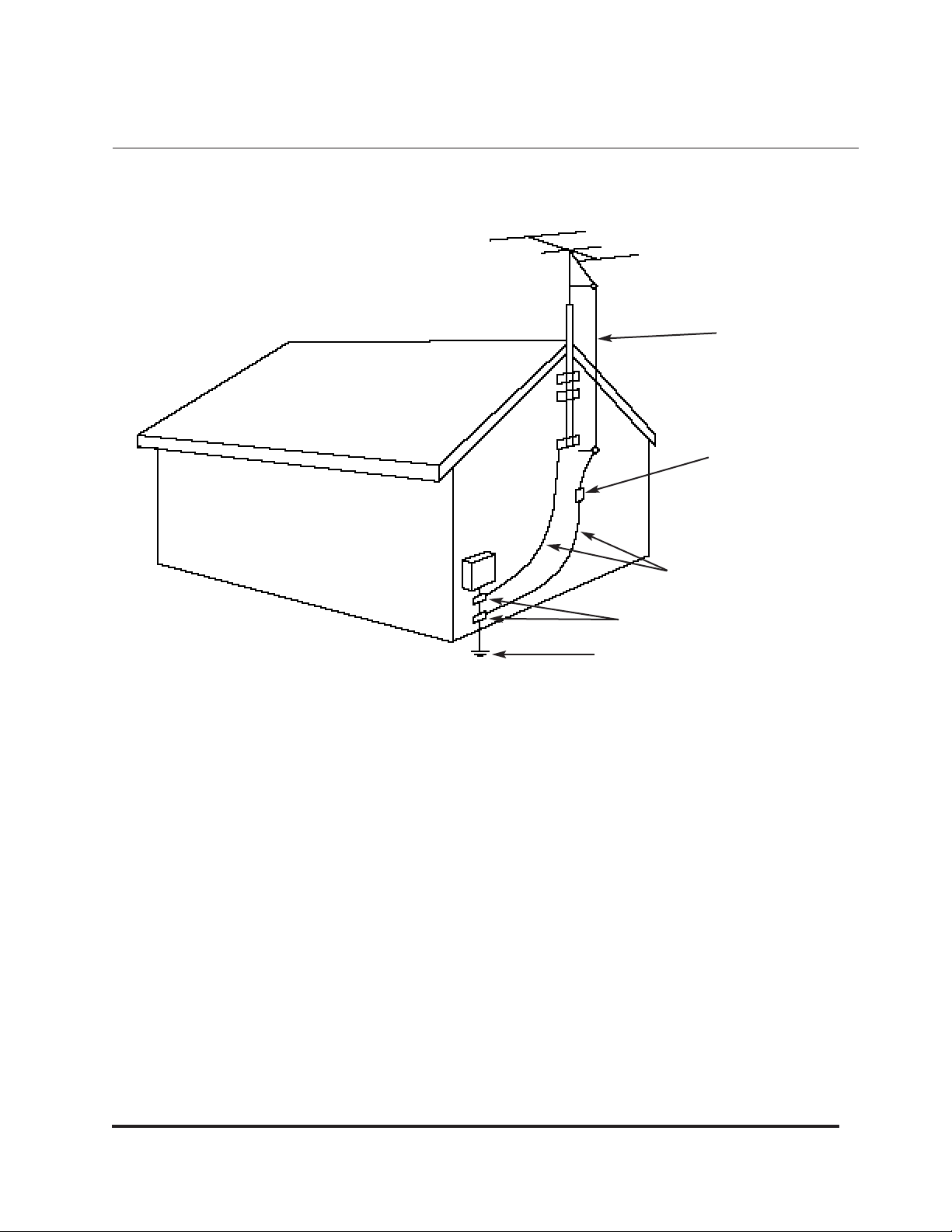
FIGURE-1
EXAMPLE OF ANTENNA GROUNDING AS PER NATIONAL ELECTRICAL CODE
ANTENNA
LEAD IN
WIRE
ANTENNA
DISCHARGE UNIT
(NEC SECTION 810-20)
GROUNDING CONDUCTORS
(NEC SECTION 810-21)
GROUND CLAMPS
POWER SERVICE GROUNDING
ELECTRODE SYSTEM
(NEC ART 250, PART H)
Page 6

JBL SP MK II A/V SURROUND PROCESSOR
THX®CONTROLLER
FOR PEOPLE WHO DON’T READ MANUALS
Please read this one. The time you invest will be worth it.
If you feel you absolutely do not have time to read it just now, here is a short list of key
information you will need in order to get the most from your SP MK II. Reviewing these
points will take only a few minutes.
• PLANNING AND INSTALLATION GUIDES: An introduction and overview of surround
sound, Home THX Audio, and the SP MK II
• Installing your SP MK II
• Calibrating and using your SP MK II
• Fine Tuning your system
The time you can save by having this information at your fingertips will more than pay
for itself.
IF YOU DON’T HAVE TIME TO READ THIS MANUAL, A STEP-BY-STEP QUICK INSTALLATION GUIDE IS PROVIDED ON THE NEXT PAGE. IN ORDER TO ACHIEVE OPTIMUM
SYSTEM PERFORMANCE, IT IS STILL ESSENTIAL THAT YOU READ AND UNDERSTAND THE MATERIALS PRESENTED IN THIS MANUAL.
THE LUCASFILM THX DEMONSTRATION VIDEODISC “WOW!” IS REFERRED TO IN
THIS MANUAL. WE SUGGEST THAT YOU READ THE INFORMATION PROVIDED ELSEWHERE IN THIS MANUAL DESCRIBING THE MATERIALS PROVIDED ON “WOW!”.
1
Always Use 120V AC
This unit is designed for operation with
120V AC unless specifically noted on
the shipping container or AC power
cord. Never connect the unit to an outlet supplying a higher voltage. This
may create a fire hazard.
Handle the AC Power Cord
Gently
• Do not disconnect the plug from the
AC outlet by pulling the cord; always
pull the plug itself. Pulling the cord may
damage it..
• If you do not intend to use your unit
for any considerable length of time, disconnect the plug from the AC outlet.
• Do not place furniture or other heavy
objects on the cord, and try to avoid
dropping heavy objects upon it. Also
do not make a knot in the power cord.
Not only may the cord be damaged, it
can also cause a short circuit with a
consequent fire hazard.
Place of Installation
Place the unit on a firm and level surface. Avoid installing your unit under
the following conditions:
• Moist or humid places.
• Places exposed to direct sunlight or
close to heating equipment.
• Extremely cold locations.
• Places subject to excessive vibration
or dust.
• Poorly ventilated places.
Do not obstruct the ventilation slots on
the top surface of the unit by placing
objects over them. Otherwise, the temperature inside the unit may rise, possibly affecting its long term reliability.
Do Not Open the Cabinet
To prevent shock hazard, do not tamper with internal components for
inspection or maintenance. JBL
Synthesis does not guarantee against
performance degradation resulting
from any modification.
If water, a hairpin, wire, or other object
enters the unit, immediately extract the
plug from the AC outlet to prevent
shock and consult your dealer or JBL
Synthesis service department. If you
use the unit under this condition, it may
cause a fire or shock hazard.
Moving the Unit
Before moving the unit, be sure to pull
out the power cord from the AC outlet
and disconnect the interconnecting
wires with other units.
Cleaning
When the unit gets dirty, wipe it with a
soft dry cloth. If necessary, wipe it with
a soft cloth dampened with mild soapy
water and then with a dry cloth. Never
use benzine, thinner, alcohol or other
volatile agent, and avoid spraying an
insecticide near the unit.
Page 7

A STEP-BY-STEP “QUICK GUIDE”
INSTALLATION OF YOUR SP MK II
1. You will require the following items: Left/right front speakers, two surround speakers,
necessary audio amplifiers, and an audio-video source plus necessary interconnect
cables. Additional options include a center channel speaker, and subwoofer or
THX–certified loudspeaker components.
2. Place the speakers and connect them to your amplifiers. Be sure to observe proper
polarity. A typical front speaker placement diagram is found on page 14. A dipolar surround speaker placement diagram is found on page 15.
3. Connect the appropriate interconnect cables between the outputs of the SP MK II to
the audio amplifier inputs. Be sure to turn off the electronic crossover if you are not
using a subwoofer. The push switch is found on the rear panel of the SP MK II. Also
note than an electronic crossover is provided for a subwoofer on the surround channels as well. If your surround speakers have woofers of less than eight inches in diameter, we suggest that you leave the surround channel electronic crossover engaged.
4. Connect the output of an audio-video source such as a laser disc player or Hi Fi
VCR to the SP MK II.
5. Turn on the SP MK II.
6. Using the handheld remote control, set the following:
MODE: Dolby®Pro Logic™ or Home THX Cinema.
CENTER: On, if a center speaker is used.
AMBIENCE: REF
PANORAMA: Center position on.
DELAY: Set to 20 mS.
7. Make sure the Bass EQ is turned off (full counterclockwise) and set the Input Level
control to the 12 o’clock position.
8. On the front panel of the SP MK II, turn on the Noise Sequencer. The test signal will
start at the left front channel and go clockwise around the room. If you are not using
side speakers, turn off the side channel output switch on the rear panel. Adjust the
Output Trim Level controls so that the volume is the same from each speaker at the listening location. We recommend the use of a sound pressure level meter, if available,
set for “C” weighting, “slow. ” Set each speaker for 85dB sound level using the internal
noise sequencer.
9. Turn off the Noise Sequencer. Select a Dolby Surround encoded movie on laser or
HI-FI VCR to verify system performance.
10. Read the rest of this manual for additional information regarding the fine tuning of
2
Page 8

your system!
MOTION PICTURE SOUND: A BRIEF HISTORY
In the early 40’s, the large movie studios owned their own theatres and could enforce
quality standards. In those days motion picture theaters provided higher quality sound
reproduction than home radios or phonographs.
An anti-trust action forced the studios to sell their theatre holdings in the 50’s. When the
theatres became independently owned, each theatre could choose which films it wanted
to show. In turn, the studios eliminated their technical staffs which had been responsible
for maintaining sound quality standards. As a result, the quality of sound in the theatres
failed to keep pace through the 50’s and 60’s.
The turning point came in the 70’s with the introduction of the Dolby Stereo
®
recording
process by Dolby Laboratories. The consumer electronics market tends to think of Dolby
exclusively as a noise reduction system used in cassette decks, but a significant portion
of Dolby’s business is in the professional audio industry. Dolby Stereo allows four channels
of sound to be recorded on the two available optical soundtracks of a 35mm movie print,
with excellent results. One of the first commercial successes of this new technology was
STAR WARS in 1977.
The impact of STAR WARS on the movie-watching public is har d to over estimate. The
quality of the sound track caught everyone’s attention and changed what people expect-
ed from film sound. Suddenly, people rushed to see new releases in better-sounding theatres, and the ones which upgraded their sound systems were rewar ded with incr eased
revenues.
Unfortunately, there was no standard of performance for the sound systems in theatres.
Even the best auditoriums sounded different from each other and fr om the sound the
director heard in the film studio because of variations in room acoustics and sound systems. In 1982, George Lucas gave his full support to create a new movie theatre sound
system standard: the THX Sound System.
The THX Sound System was designed to complement and enhance the playback of
Dolby Stereo, which was the established standard for film sound recor ding. THX picked
up where Dolby Stereo left off, encompassing standar ds and technologies for power
amplifiers, speakers, patented Lucasfilm technology and the acoustics of the theatres
themselves to ensure the best possible reproduction of movie soundtracks.
By 1991, THX systems had been installed in nearly 500 movie theatres and studios worldwide, with many more in various stages of construction. THX has become the industry
standard for post-production mixing facilities as well as for theatres and/or studios.
3
Page 9

In 1986 the sales and rental of home video software equalled theatrical ticket sales.
George Lucas found himself back where he started—with no control over how his films
would actually sound in the home. For that reason, the Lucasfilm Home THX Audio
System was designed to accurately bring the theatre experience home.
THE GOAL OF LUCASFILM HOME THX AUDIO SYSTEM
The film industry has a clearly-defined standard for the reproduction of film soundtracks. In practice, however, achieving the standard is quite challenging. Perhaps the
best method for measuring the success of various systems is by looking at their
acceptance by the professionals who use them. The THX Sound System clearly dominates the field, both in theatres and in film studio dubbing stages.
If you wish to hear the soundtrack as the director did, you must duplicate the sonic
experience of the dubbing stage in your home. And the majority of all standardized
dubbing stages now use THX Sound Systems.
The objective of Lucasfilm Home THX Cinema is to bring precisely this performance
standard to a home environment in order to give the filmmaker a transparent path
between his creation and the experience of the viewer.
In general terms, this requires solving the problem of transferring sound from a large
movie theatre or a dubbing stage to a smaller home environment without compromising its character (a non-trivial task, in view of the radically differing acoustical properties of large and small rooms). In addition, there are many specific design objectives
which define the total performance of the system:
• a wide frequency range, extending to the limits of audibility
• smooth, naturally balanced overall sound and excellent dialog intelligibility
• a wide dynamic range with extremely low distortion
• well-matched timbre (tonal balance) between front speakers and
surround speakers
• precise localization of specific sounds
• envelopment by ambient soundfield
• superb performance with non-film music sources
4
Page 10

PLANNING AND INSTALLATION GUIDES
A CHECKLIST FOR PLANNING AND INSTALLING YOUR HOME THX
AUDIO SYSTEM
Introduction and Overview
The SP MK II is the most advanced surround processor/control center yet produced,
incorporating state of the art surround processing circuitry. The SP MK II also features
Lucasfilm Home THX Audio processing circuitry which has been specifically designed
to provide new levels of enhancement to motion picture soundtracks. In addition to
extensive audio capabilities, the SP MK II incorporates a comprehensive audio-video
switcher. The entire unit is microprocessor controlled utilizing both liquid crystal and
LED display systems to provide visual indication of the operational status.
MUSIC SURROUND LISTENING PARAMETERS
The SP MK II incorporates a comprehensive menu of pre-programmed modes for playback of music sources. Some settings may be altered to suit listening tastes or environmental requirements.
MOTION PICTURE LISTENING PARAMETERS
Four parameters for the playback of motion picture soundtracks are provided including: Dolby Pro Logic™, THX Home Cinema (Pro Logic surround decoding and THX
audio processing), 35mm Motion Picture and 70mm Motion Picture.
A complete description of SP MK II surround parameters is found on page 7.
SP MK II FEATURES
In addition to a wide range of listener-selectable surround parameters, the SP MK II
provides a number of unique and beneficial operating procedures. These include:
automatic input balance calibration, a built-in test noise sequencer, output level trim
controls, bi-ampable main and surround channels, A/V input switching, and a separate
A/V record output circuit.
Descriptions of SP MK II features are found on page 25.
5
Page 11
SP MK II Surround Processor
The SP MK II THX controller incorporates a combination of existing technology and
new, proprietary and patented Lucasfilm developments. This enables the system to
take advantage of existing standards for film sound for maximum compatibility, while
also improving home reproduction quality of film soundtracks (which were, after all,
recorded for playback in large auditoriums). The entire controller package is a combination of:
• Proprietary surround technology for use with both surround encoded and nonencoded stereo audio sources
• Dolby Pro Logic Surround for encoded motion picture, stereo CDs, and television
audio soundtracks
• THX re-equalization, de-correlation, timbre matching circuitry
• A THX electronic crossover for bi-amplification of the main front speakers and a sep-
arate electronic crossover for optional bi-amplification of the surround channels
• Level Calibration to the original sound pressure levels heard in the theatre
6
Page 12

SP MK II OPERATING PARAMETERS
The SP MK II offers a full array of surround parameters which will accommodate all
types of music and movies. Conventional motion picture surround processing technology was never intended for music reproduction, so virtually every other manufacturer
of surround processors has chosen to offer digital soundfield processing, or “DSP,” for
music listening enhancement. While DSP is rather technically ambitious, the results are
often artificial. Digitally-generated reverberation or effects are added to the natural or
studio-created ambience of the original recording. The result is usually not representative of the original recording or the desired new venue.
The SP MK II surround parameters are tailored for specific movie and music applications. We suggest that you experiment with the various modes. A limited amount of
audio signal delay is available to enhance some modes. Changes you may make in
audio signal delay settings are automatically stored in selected modes. The following
descriptions of each mode will help you to select the appropriate one for your specific
listening tastes.
ROCK
This mode was designed to give an exciting presentation of typical multi-track rock
recordings. The Rock mode is unique in that it provides full frequency range, stereo
surround channels. No other processor is capable of delivering true stereo surround.
Any audio signal delay setting may be used (up to 80 ms), and the Panorama control
may be adjusted to suit the recording. (An explanation of the Panorama function is
found on page 26 in this manual.) The logic steering speed is “fast.” In the Rock mode,
you can expect to hear a full soundfield which totally surrounds you with a significant
amount of back channel information.
Music that has a great deal of stereo separation will be reproduced with an excitement
and intensity that is similar to listening through headphones but with the visceral
impact that only dynamic loudspeaker systems can produce. The Rock mode will also
yield exciting results with most New Age and electronic music as well.
POPULAR
The Popular music mode is intended for a natural presentation of the majority of popular music titles. The perspective is more frontal and not quite as “wrap-around” as the
Rock mode. The surround channels are monophonic and are full frequency response.
Any audio signal delay setting may be selected (up to 80 ms), as well as Panorama.
Logic speed is “fast.” The Popular mode is the most universal for a wide variety of
music, including rock, light rock, Broadway shows, etc.
7
Page 13

JAZZ
The Jazz mode is particularly well suited to any live recording of popular or jazz music.
The soundstage will be primarily frontal with ambience coming from the surround
speakers. Separation of instruments will not sound exaggerated, but will sound like an
ensemble playing in front of you. The natural room acoustics of the recording environment will be preserved. The Jazz mode delivers full-range mono surround channels
with fully-selectable time delay, Panorama and “fast” logic speed. “New” jazz and
fusion music also benefit from this mode. Blues fans will find the Jazz mode the most
effective, especially on live recordings.
HALL 1
This music mode is a “purists” mode suitable for any music where minimum processing is desired. It is a passive circuit (no steering logic) similar to the L-R circuit often
erroneously referred to as the “Hafler” circuit. This circuit extracts ambience from a
natural stereo recording and places it in the surround channels. Front channels are
completely unprocessed. A special equalization curve is applied to the surround channels to emulate the natural decay of high frequencies over distance for more natural
hall ambience. Chamber music is natural and enveloping in this mode, as are all small
acoustic ensembles. The listener is placed close to the performance.
HALL 2
The Orchestra mode, like Chamber, uses no processing on the front channels, and
center channel is disengaged. Orchestra mode applies steering logic only to the surround channels only with a narrow matrix providing a “mid-hall” perspective. This setting is ideal for larger symphonic works. You may switch on, at your option, the center
channel speaker in the ‘Orchestra’ mode. Steering logic is engaged on the front sound
stage when the center speaker is switched on. Audio signal delay settings may be
extended to 80 ms.
35MM MOTION PICTURE
The decoding matrix is identical to the one used in the Dolby Pro Logic mode, but with
higher speed steering logic and a more extended frequency response on the surround
channels. Audio signal delay settings may be extended to 50 ms.
70MM MOTION PICTURE
This setting is identical to 35mm but delivers controlled blending of left/right front
channel information into the surround channels to provide a sense of spaciousness
with software which has little or no encoded surround information. Audio signal delay
settings may be extended to 50 ms.
8
Page 14

DOLBY PRO LOGIC
This is the consumer version of the system used in theatres to decode four channels of
sound from the film’s soundtrack and provides performance identical to that of theatrical
Dolby decoders. A sophisticated microprocessor control system in the SP MK II r e-configures the steering logic time constants to those of Pro Logic. The outstanding circuit topology used within the SP MK II delivers Pro Logic decoding with superb sonic quality. Audio
signal delay settings range from 15 to 30 ms in 5 ms increments.
MONO ENHANCE: This mode generates a synthesized surround field from a monaural
source. A pleasing, spatial effect can be derived from older music r ecor dings, mono TV
broadcasts, or movies mixed in mono. The Panorama control is operative in Mono
Enhance.
BYPASS: The Bypass mode allows the listener to electronically remove the SP MK II surround processing circuits fr om the audio signal path. Only the left and right fr ont speakers
and subwoofers remain functional. A single buffered gain stage with r emote contr ol of volume remains in the signal path.
LUCASFILM HOME THX CINEMA
Lucasfilm Home THX Cinema incorporates Dolby Pro Logic surround decoding along with
additional audio enhancements.
RE-EQU ALIZATION: Re-Equalization is necessary to compensate for the fact that the
soundtracks in films sound “bright” in a home environment. This r esults fr om a combination of the way we perceive sound in large auditoriums vs. small rooms and the theatre
equalization which has become standardized throughout the movie industry. The ReEqualization circuitry compensates precisely for these differences, r estoring the sound to
its natural balance and minimizing listening fatigue by reducing harshness in the high frequencies.
DE-CORRELATION: The SP MK II incorporates a proprietary de-correlation circuit which
alters the phase/time relationships between surround channels to diffuse the per ceived
sound. This eliminates the mono effect in the surround channels and helps to restor e the
enveloping characteristic that is a system design goal.
TIMBRE-MATCHING: The timbre or tonal balance of sound changes depending on
whether it comes from in front of you or from the sides. This has to do with the shape of the
outer ear. This is especially noticeable when the director pans a sound from the fr ont
channels into the surround channel.
The character of the sound changes as the effect moves from the front to the surr ounds,
even when the speakers are perfectly matched. This may reduce the realism of the effect.
9
Page 15

Fortunately, this characteristic can be compensated for by use of very specific and
proprietary equalization applied to the surround channels only. Timbre-matching circuitry is included in the SP MK II.
BI-AMPLIFICATION: This technique of separately powering the main speakers and
subwoofer(s) dramatically reduces distortion while expanding the useful dynamic
range of the system. System distortion is substantially reduced. In addition, bi-amplification enables the front speakers to be significantly reduced in size without any penalty in performance, allowing them to be more easily placed for the best imaging. The
SP MK II includes a specific low frequency, steep-slope electronic crossover specifically designed to match the requirements of Home THX speakers.
10
LT
RT
Input
Level &
Balance
Controls
Elements of the Home THX Audio System:
HOME THX CONTROLLER
PROPRIETARY LUCASFILM CIRCUITRY
L
C
R
SUR SUR
Dolby Pro-Logic
Surround Circuity
Subwoofer
Electronic
Crossover
TimbreMatching
L
C
R
SUB
Re-Equalizer
Decorrelation
Output
Level
Controls
L
C
R
SUB
SUB
SUB
© 1990 LucasArts THX
Page 16

PLANNING YOUR HOME SURROUND AUDIO SYSTEM
Home surround systems are primarily intended for use with video. The SP MK II, however, has been especially designed to work equally well with both non-encoded
sources (CDs, cassettes, broadcast television and records) as well as surroundencoded video sources (motion pictures and broadcast television).
You can use existing equipment to begin building a complete Home THX Audio
System. Although it will not be a full-fledged THX Audio System until it is complete, the
incremental improvements will be clearly heard as each step is taken toward the goal.
You should start with the SP MK II THX controller and upgrade the system a step at a
time by adding either the THX dipolar surround speakers or the main front speakers
with a subwoofer.
PLEASE NOTE: The THX specification includes an electronic crossover for the front
speaker system. If you are using THX speakers without the SP MK II, or other THX controller, some provision must be made for an appropriate crossover between the subwoofer(s) and the front speakers.
The list of equipment needed for a complete SP MK II Home THX Audio System installation is fairly straightforward:
• A SP MK II THX controller.
• At least six channels of amplification for left, center, right front channels plus two sur-
round speakers, and one or more subwoofers.
• Identical THX left, center and right front speakers with appropriate stands or mounting brackets to facilitate aiming them directly at the primary listening area.
• One or more THX subwoofers (depending on room size) designed for use with the
THX front speakers.
• A pair of THX dipolar surround speakers with appropriate stands, or attached mounting brackets to position them at least two feet above ear level when seated.
• Assorted interconnecting cables and speaker wires.
A home theater also requires a large screen television and the best possible video
sources. The best A/V sources are laserdisc or home satellite followed by off-the-air
television, cable or VHS HiFi.
A 31"–35" direct-view television may be appropriate in smaller rooms but cannot impart
the theatrical experience of having your field of vision dominated by the size of the
image on the screen. Attaining this effect with a 35" television requires sitting uncomfortably close to the screen.
11
Page 17

ELECTRONICS PLACEMENT
• Cabinets should be used to conceal equipment which must be placed near the
screen. The lights and visual displays on the equipment should not distract the viewer.
• Ample ventilation must be provided, preferably through convection, to avoid fan
noise.
VIDEO VIEWING REQUIREMENTS
• The primary seating areas should be centered in front of the picture.
• NTSC video looks best at a seating distance from 3–5 times the width of the screen
for maximum perceived clarity, however, you may choose to sit as little as 2.5 times the
screen width to achieve maximum visual impact and involvement.
• Ambient light should be minimized to maximize video contrast performance particularly with projection video display systems.
• The main front speakers should flank the screen and be placed with reasonable symmetry with respect to adjacent walls.
• The screen should be well away from side walls. The front speakers have broad horizontal dispersion and it is best to minimize side wall reflections.
SPEAKER PLACEMENT
The SP MK II may be used with conventional, high quality speaker systems or with
Home THX–certified loudspeaker systems. There are some general installation guide-
12
Position of components:
Electronics
• Keep noisy components away.
• Hide distracting indicators (LEDs).
• Consider IR receiver by the screen.
• Provide cooling for power amps.
• Aim for short speakers cables (unless in
high RF fields where low levels might pick
up noise).
Page 18

lines that apply to both types of systems in terms of achieving optimum performance.
• Select speakers designed to meet your system requir ements. Don’t, for example, flushmount a book shelf speaker designed for different mounting applications. If the room is quite
large, you may require two or more subwoofers to achieve optimum performance.
Acoustically dead rooms may require higher ef ficiency speakers to achieve louder sound
levels.
If you have questions regarding the proper installation of your speakers, consult your dealer
or the manufacturer.
MAIN LEFT , CENTER, RIGHT SPEAKERS (LCR)
• The Left and Right front (L/R) speakers should be placed close to the edges of the scr een
to eliminate the disorientation which results when sounds appear to occur well away from
their visual on-screen location. Some allowance must be made for those installations involving screens smaller than five or six feet measured diagonally. Placing the speakers immediately beside a small screen usually reduces stereo separation to unacceptable levels. Some
experimentation may be in order, but as a rule of thumb, try to place the L/R front speakers
no more than 18" to 24" from the sides of the screen.
• Try to avoid placing the L/R front speakers too close to side walls or room corners. They
should usually be placed no closer than 18" to 24" from corners and side walls. Conventional
speakers should be toed in slightly towards the seating areas. THX–certified speakers will
usually require no toe in, however some toe in will assure even lateral coverage of the seating area and reduced side-wall reflections.
•
THX LCR speakers
are designed to be used
vertically only.
If they
must be either above or
below the screen they
must be properly aimed
towards the listener.
Proper aiming is critical
because THX speakers
are intentionally quite
directional in the vertical
plane to focus sound
energy to improve dialog
intelligibility and image
localization.
13
Home THX Front Loudspeakers
Controlled Vertical Dispersion
Elements of the Home THX Audio System:
• Reduces reflections from floor and ceiling
• Projects more direct energy toward listeners
© 1990 LUCASA THX
Page 19

• The Center speaker should be directly above or below the screen. When possible,
try to keep the center speaker tweeters as close to the level of the tweeters in the L/R
speakers (no more than a two foot difference) so that lateral audio pans do not create
noticeable changes in vertical localization.
• Placing the LCR speakers below the screen is preferable since aiming them upward
maximizes the usable listening area. Placing the Center speaker directly in front of a
television is fine as long as it does not obscure any portion of the screen, provided it is
magnetically shielded. All THX LCR speakers are magnetically shielded.
SUBWOOFER PLACEMENT
• Subwoofers do not have to be placed extremely close to the front channel speakers
but placement will affect the low bass.
• Leave yourself some leeway during final installation for minor movements to minimize
room modes. Corner placement will yield the most deep bass, but this excites the
maximum number of standing waves resulting in uneven frequency response. Use of
multiple subwoofers will increase bass output and allows one subwoofer to smooth
irregularities created by room modes. Placement near a video projector is acceptable
since all THX subwoofers are magnetically shielded.
14
SPEAKER PLACEMENT:
Front Speakers
SCREEN
L
R
Less than 2 feet
C
Page 20

SURROUND SPEAKER PLACEMENT
• THX–certified surround speakers should be located to the sides of the listeners
instead of behind them. If the viewing area is more than one row deep, place the surround halfway back within the area. If architectural constraints prevent ideal placement
of the surrounds it is generally best to err on the side of being further to the rear of the
room.
• The surround speakers should be located at least two feet above the listener for the
best results. And they should be located at equal heights for uniform frequency
response. Placement close to the ceiling will result in slightly more mid-bass performance. Try to place them so the null is aimed towards the seating area.
• THX dipolar surround speakers should be placed so the positive polarity side of the
speaker faces towards the front of the room.
• Conventional surround speakers should be placed behind the listening area and
should also be placed mid wall level or higher.
A more focused surround sound effect will result by aiming the speakers towards your
listening area. If you prefer a more diffuse surround sound effect, then aim the speakers across the back of the listening area. The THX de-correlation circuitry within the SP
MK II will help to create the proper effect for motion picture listening but will be automatically defeated in other surround modes designed for listening to non-encoded
music sources.
15
FRONT SPEAKER
Surround Loudspeakers
Null
Listener
Null
Page 21

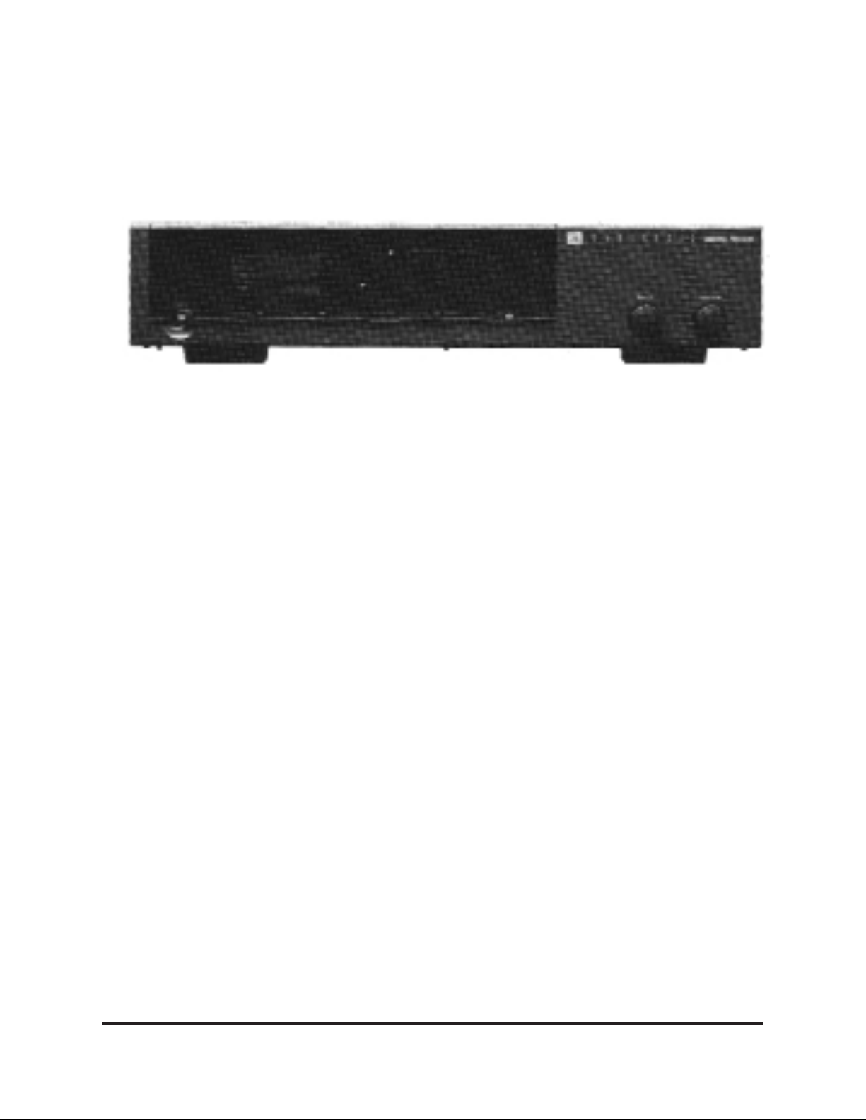
INSTALLING YOUR SP MK II
For convenience of operation, we suggest that you
run all your main audio and video sources through
the SP MK II. Four inputs (including the tape monitor
input) accept audio and composite video sources
while the remaining two accept audio and S-type
(Y/C) video from S-VHS, S-Beta, and some laser
video players and satellite receivers.
The SP MK II does not transcode the video signals.
Composite video will only appear on the composite
video outputs (monitor and record). Likewise, S-type
signals will only appear on the S-type outputs.
The SP MK II can become the heart of a home entertainment environment. Every type of consumer audio
source can be used with the SP MK II except a
turntable. If you wish to use a turntable/cartridge with
the SP MK II, you will require a preamplifier or stereo
receiver to provide proper pre-amplification and RIAA
equalization for the magnetic phono cartridge. The
main output or tape record output from the preamp or
receiver should be connected to one of the six audio
inputs on the SP MK II.
The main audio outputs of the SP MK II are designed
for use with either THX–certified or conventional
speakers. The electronic crossover switch (on the
back panel) must be engaged when using THX–certified speakers (separate subwoofer and LCR speakers).
If you have a small room and are only using one subwoofer, use the Mono Sub output.
If you are using a single pair of conventional surround
speakers or another manufacturers’ THX dipolar surround speakers, use the LB (left back) and RB (right
back) outputs.
You will have to reverse the polarity
of the surround speakers with that of the front
speakers!
16
Page 22

SP MK II FRONT PANEL DISPLAY
The display system used on the SP MK II uses a combination of light emitting diodes
(LED) and liquid crystal (LCD).
PRIMARY FUNCTIONS: Surround operating modes, volume settings, time delay set-
tings, and panorama settings, are displayed on the liquid crystal panel. The selected
surround operating mode is always displayed. Changes in volume (front or back channels), time delay settings, and panorama settings, are momentarily displayed (about
ten seconds) on the second line of the liquid crystal display.
INPUT LEVEL: The input gain control on the front panel is adjusted to illuminate the
Input Calibrate display to 0 dB. Then, the channel output trim controls on the back of
the SP MK II are individually adjusted to achieve proper output levels with sufficient
headroom and freedom from amplifier or speaker overload.
OUTPUT VOLUME: Volume settings have a range from –85 to +15. These settings do
not necessarily relate to dB equivalents. Normally, the output volume level is set to the
0 REF setting when playing reference “0 dB” level signals from videodiscs and VHS
HI-FI video cassettes.
AUDIO SIGNAL DELAY: Delay settings can be adjusted from 15 to 30 ms in the Pro
Logic or THX Cinema modes, up to 50 ms in 35 mm and 70 mm movie surround
modes, and up to 80 ms in some music modes. Changes in audio signal delay settings are automatically retained in the memory of the SP MK II.
PANORAMA: Panorama settings may be adjusted from –50 to +50 and will vary to
taste depending on the individual recording. Panorama cannot be engaged in the Pro
Logic or THX Cinema modes. Panorama settings cannot be stored because they are
also program source dependent.
SECONDARY FUNCTIONS: Which include: Center Channel On or Off, Sibilant and
Re-Equalization (Re-Eq) Filters, Mute, Source, Record Select, and Center Boost, are
displayed by LEDs behind the front panel window. The status of functions including
Center Front On/Off, Noise Sequencer, Input Balance, are displayed by LEDs directly
above the button which turns the function on or off.
The Re-Eq and Center Channel On functions may be selected in all music modes.
Center channel is Off when Hall 1 or Hall 2 surround modes are selected but it can be
engaged, if desired. Re-Eq is only selected automatically in the THX Cinema mode but
it may be disengaged in the THX Cinema mode or engaged in other modes. Because
the need of Re-Eq in non-THX modes is program source dependent, it cannot be
stored in other modes.
17
Page 23

SET-UP AND CALIBRATION
TESTING FOR PROPER SPEAKER POLARITY
Proper polarity throughout the system is required before level calibration can be established. Wiring the loudspeakers in proper polarity is essential for precise localization of
images and bass response—both important goals of the Home THX Audio system.
Achieving proper polarity is made more complicated if amplifiers of different types are
used in the system. Some amplifier designs invert the polarity of their output relative to
the input signal. Speakers attached to these amplifiers must have their polarity inverted again to get it back where it belongs.
The best way to ensure proper polarity in any home audio system is to compare each
speaker to a single speaker which is used as the reference for the system. We will use
the Left front speaker as the reference in our example. Check the wiring color code on
both the amplifier and speaker jacks to verify correct polarity.
L-R POLARITY: Check Left-Right polarity by listening to both speakers in the stereo
bypass or center speaker off mode. Listen for a solid center image. If in doubt, reverse
the leads on the Right speaker only and compare the results. Speakers with mismatched polarity will have a poorly-defined image smeared all over their end of the
room. Some listeners will even feel strange pressure sensations in their ears! If you
have any doubt, try using the pink noise on Chapter 6 of
WOW!—this should make the
difference extremely clear.
L-C POLARITY: Check Left-Center polarity in the Home THX Cinema mode by feeding
mono program material (dialog, or Chapter 6 of
WOW!) and setting the input balance
to the left so as to get equal sound pressure levels out of both the left and center
speakers. Again, listen for a solid image between the left and center speakers.
RELATIVE SUBWOOFER POLARITY: If multiple subwoofers are used, it is important
to have their polarity with regard to each other correct. Reverse the polarity of one of
the two subwoofers while program material with deep bass is playing (being careful
not to momentarily short the two speaker leads to one another). The pink noise on
Chapter 6 of
WOW! can be used as a constant source of bass energy by shutting off
all speakers except the subwoofers. You will immediately notice either a loss or an
increase in bass. The correct polarity is the one which exhibits the most bass.
ABSOLUTE SUBWOOFER POLARITY: It is also important for both subwoofers to
have the correct polarity with regard to the rest of the system. Now that the LCR speakers are all matched, play some program material (or Chapter 6 of
WOW!) with significant energy around 80 Hz. Reverse the polarity of all subwoofers in the system and
listen again. The polarity with the greatest bass output in this vital region is correct. (A
third-octave warble tone centered on 80 Hz is ideal for this test and is available on
some test compact discs.)
18
Page 24

SURROUND POLARITY: Using the Pro Logic mode (not the THX mode) stand by the
screen and face the surround speakers. With strong surround program materials (such
as Chapter 11 on
WOW!), you should hear a solid center image between the surround
speakers and your standing position.
ADDITIONAL HINT: After system polarity checks are completed, use the internal noise
generator in the SP MK II to verify proper hookup. The burst of noise should start at left
front and move clockwise around the room. The Noise Sequence switch on the rear
panel of the SP MK II should be set to turn off the L and R Side outputs.
INPUT LEVEL CALIBRATION
It is necessary to adjust the input level of sources in order to get the best results from
your SP MK II. This adjustment yields the best dynamic range from the surround
decoder circuitry, preventing overload distortion or excessive background hiss.
Correct calibration also ensures accurate tracking of the steering logic and the modified Dolby B noise reduction system in the Dolby Pro Logic circuitry.
A test tone (Chapter 5 on
WOW!) can be used in conjunction with the front panel LED
level display to calibrate the system. Feed in the test tone and adjust the input level so
that the 0 dB LED just reaches full intensity. Under normal operating conditions, the
red LED should never do more than flicker occasionally (which indicates input overload).
If no test tone is available, you can still calibrate the system with reasonable accuracy
by turning up the input level control until the 0 dB LED glows brightly during medium
level passages in movies, but not high enough to illuminate the red LED. Movies are
duplicated at slightly different audio levels, so you may need to touch up this adjustment occasionally. You may expect a 1 to 3 dB variation among various film transfers.
AUTO BALANCE/INPUT BALANCE
The Automatic Input Balance circuit corrects improperly balanced software, which
tends to pull the dialog off center. These channel errors occur in the multiple copying
stages between the original master and your source. In most cases the autobalance
circuitry within your SP MK II will provide extremely accurate correction. Occasionally,
some software may have errors beyond the correction ability of the internal circuitry. To
manually correct for such imbalances, press the left or right button located on the right
side of the front panel of the SP MK II to turn off the autobalance circuit. With the
Center output
on but with the the Center Speaker amplifier turned off, push the left or
right channel button to minimize leakage of center channel dialog to left or right speakers. The liquid crystal display will indicate the amount of level change. Turn the center
19
Page 25

channel amplifier back on to restore normal system operation. When you wish to
restore Autobalance operation, push the AUTO button (located between the left and
right buttons) to disengage manual balance.
OUTPUT LEVEL CALIBRATION
The SP MK II provides individual channel output level controls. These allow you to
compensate for differences in amplifier and speaker sensitivities and for placement
variations from installation to installation. These set-and-forget adjustments are essential for reproducing proper soundstaging and image localization. These controls are
located on the rear panel of the SP MK II just above the audio output jacks.
Adjusting the output levels is done after completing the input level adjustments. Once
this is completed, system volume changes are made using the up/down buttons on the
infrared remote control.
The best way to adjust the output level controls is by using a dB Sound Pressure Level
(SPL) meter in conjunction with the internal bandwidth-limited pink noise generator in
the SP MK II. The goal is to set the volume at the primary listening position to read 75
dB SPL
(C-weighted, slow mode) from each speaker in sequence, using the individual output level controls. You should use the meter pointing straight up towards the
ceiling.
The “average” setting of the individual output level controls should be ideally near the
midrange of their rotation. The simplest way to achieve this is to set the Master Volume
at 0 REF on the liquid crystal display and then adjust each individual channel output
trim control (located on the rear panel) until a 75 dB SPL is achieved. The Master 0
REF setting becomes the calibrated playback setting for any software which has been
dubbed carefully, with proper attention to soundtrack levels. Some adjustments to the
input level and input balance controls may be required to compensate for soundtracks
with different levels and channel balance.
In the absence of a dB SPL meter, it is possible to set the output level controls by ear.
Use the built-in test noise generator in the SP MK II to adjust all volumes to sound the
same as they cycle around the various speakers. The test signal is bandwidth-limited
pink noise to minimize the problem of timbre shifts influencing the setting of levels.
Even so, using non-THX-certified loudspeakers may make this more difficult to judge,
due to variations in spectral balance between the various speakers—especially mismatched left/right front and center speakers. Simply get as close as you can! The system should then be reasonably well balanced, although of course it is not actually calibrated for precise playback levels.
20
Page 26

ADJUSTING THE DOLBY TIME LINK™ DIGITAL AUDIO SIGNAL DELAY SYSTEM
All Dolby Pro Logic decoders incorporate an audio signal delay to the rear speakers.
The SP MK II incorporates two high-performance, discrete-circuit channels of Dolby
Laboratories’ advanced new digital audio signal delay system: Time Link.
The Dolby Pro Logic process occasionally yields erroneous leakage of front channel
sounds to the rear. TIme Link, a digital signal delay circuit, is used to reduce the perceived level of leakage because of the “Hass” or precedence effect. When the front
channel information leaks into the surround speakers, we end up hearing this leakage
out of the surround speakers following the arrival (at our ears) of the front channel
information.
Time Link allows the sound coming from the front speakers to reach the viewer before
the arrival of sound from the surround speakers.
21
The optimum Time Link setting
depends on the distance between
the main seating area and the front
speakers, and the distance
between the main seat area and
surround speakers
Refer to the graph for choosing the
best setting in any given situationmeasure the two distances and look
to where they meet on the graph.
The shaded areas will indicate the
best setting for the delay.
If in doubt, simply set Time Link for
20 ms of delay. The setting will be
stored in the memory of the SP MK
II until you change it. You may also
use Time Link to enhance and align
arrival times of certain music surround modes available in the SP
MK II. The audio signal-delay settings can be stored for each applicable music or movie mode independently of the Pro Logic or Home
THX Cinema modes.
PREFERRED ACCEPTABLE NOT RECOMMENDED
25 ms 20 ms
40
35
30
25
20
15
10
5
DISTANCE FROM REAR SPEAKERS (FEET)
0
0 5 10 15 20 25 30 35 40
DISTANCE FROM FRONT SPEAKERS (FEET)
USABLE SPEAKER PLACEMENT RANGE WITH
15 ms
15 ms
15 ms
20 ms
25 ms
XX MS DELAY TIME
30 ms
30 ms
30 ms
15 ms
15 ms
15 ms
15 ms
10 ms
5 ms
HAAS EFFECT
DIFFERENTIAL
ARRIVAL TIME
Page 27

SP MK II FEATURES
The SP MK II incorporates a number of operational features which have been
designed to enhance the performance and versatility of your home surround audio
system. An explanation of the features and their uses follows each feature listing.
VARIABLE BASS EQUALIZATION: This rotary control located to the left of the input
gain control, allows boost of bass frequencies to compensate for the bass rolloff of
most full range loudspeakers in the 30 to 70 Hz range. The total amount of boost available is +17 dB over a relatively narrow range to avoid adding “chestiness” to the
sound of male voices. Normally, only a small amount of boost should be used to avoid
overloading both the power amplifier and the speaker. Bass EQ is only available on the
front subwoofer outputs and the main left and right front channels (when the THX electronic crossover is disengaged).
The full counterclockwise setting is off. Clockwise rotation introduces boost. As boost
is turned up, the center point of the boost range is moved up. As an example, a setting
between an 8 and 9 o’clock setting on the control may deliver maximum boost about
35–40 Hz while a 12 o’clock setting will move the area of maximum boost up to about
50–60 Hz. If you are using THX–certified subwoofers, or other high quality subwoofer
systems, little, if any, boost will be required once proper output levels are established.
SIBILANT FILTER: This function accessible via the remote control, engages special
circuitry which minimizes crosstalk in the surround channels caused by speech sibilants but without causing loss of high frequency detail. An indicator light on the front
panel indicates when the sibilant filter is engaged. Use the sibilant filter whenever you
hear sibilant sounds from dialog present in the surround channel.
RE-EQUALIZATION CURVE: This circuit is a part of the SP MK II Home THX control
system but is sometimes useful with other program sources. It can be manually
switched in when using other surround parameters besides Home THX Cinema. When
Home THX Cinema is selected the Re-Equalization filter is automatically engaged. An
indicator light on the front panel indicates when the Re-Equalization filter is engaged.
A motion picture sound track will sound “bright” in the home because the original
equalization curve was designed for far-field listening and for special equalization that
is standardized in the film industry. The Re-Equalization circuitry compensates for
those differences and restores normal spectral balance for the near-field listening environment of the home.
THX ELECTRONIC CROSSOVER: The SP MK II has a built-in electronic crossover
especially designed for use with Home THX–certified loudspeaker systems. It may also
offer excellent results with other subwoofer/satellite speaker systems. Consult with the
manufacturer of the speaker system. The crossover frequency of the electronic
22
Page 28

crossover is centered at 80 Hz. A switch on the rear panel of the SP MK II engages the
crossover. When disengaged, the left and right front channel audio outputs operate full
range but the subwoofer outputs still remain active.
SURROUND ELECTRONIC CROSSOVER: Some listeners may prefer some bass
extension in the surround channel particularly with some music surround settings. The
main surround outputs have a rolloff below 80 Hz at 12 dB/octave. A mono subwoofer
surround output is provided. A small woofer (8" to 10") with a response to 40–50 Hz
may be desirable for use in some environments. A switch on the rear panel of SP MK II
(adjacent to the front channel crossover) switches in the surround electronic crossover.
When using Home THX–certified dipolar surround speakers, be sure the electronic
crossover is engaged, even if you aren’t using a subwoofer. This will prevent overload
of the dipolar surround speakers by audio frequencies below 80 Hz. An output level
trim control for the surround subwoofer is located on the rear panel of the SP MK II.
TEST NOISE GENERATOR: The built-in noise generator sequences bandwidth-limited
pink noise around the room to each speaker location. The duration of the noise burst is
limited to two seconds in the Dolby Pro Logic and Home THX Cinema modes. The duration is extended to approximately four seconds in the other surround modes.
The trim controls, which can be adjusted by hand without the need for special tools, are
located on the rear panel of the SP MK II.
A switch on the rear panel (next to the electronic crossover switches) eliminates the
noise burst to the side channel/front dipole driver outputs for use with a single pair of
point source-type surround speakers, or when using conventional THX dipolar speakers.
PANORAMA: This feature, accessible via the remote, adjusts the width of the stereo
stage. Some recordings may not have enough stereo separation, and may sound
monophonic. Other recordings may have too much separation and sound exaggerated. Adjusting the panorama circuit to widen or narrow the stereo stage will correct
most recordings. When the panorama button on the remote control is engaged the liquid crystal display will provide an indication of the amount of correction.
MUTE: This function totally mutes the output of the SP MK II.
CENTER BOOST: This function, accessible via the remote, increases the output level
of the center front channel by 3 dB. Pushing the Center Boost button a second time
restores center front level to normal. Center boost may be required when listening to
some film tracks with non-THX speakers.
SOURCE SELECT: This function, available via the remote and the front panel of the
SP MK II, selects the desired A/V input.
RECORD SELECT: This function, available only from the front panel of the SP MK II,
selects the A/V source for recording purposes or to be viewed at a secondary location.
23
Page 29

The record output stereo audio is unprocessed. Composite video is not transcoded to
S-type video or vice-versa.
REMOTE INFRARED SENSOR JACK: This miniature input jack, located on the rear
panel, accepts input from a remote infrared transmitter/sensor or remote key pad. It is
provided for custom installation applications. Consult your dealer or JBL for additional
application information.
ACCESSORY CONTROL OUTPUT: This five-pin standard DIN jack located on the
right bottom corner of the SP MK II can provide trigger signals for an outboard control
box to turn on the system electronics, lower or raise a projection screen, dim or raise
room lighting, etc. Consult your dealer or JBL for additional application information.
DISPLAY CONTRAST CONTROL: This manual rotary control is located on the underside of the left side of the front panel. The relative contrast of the liquid crystal display
can be changed with this control.
FINE TUNING YOUR AUDIO SYSTEM
The procedures outlined in the previous sections should allow proper performance of
the system. There are several things you can do to “tweak” the installation even further.
In many cases, the concepts contained in this section are not necessary to achieve
the kind of impact the SP MK II and a Home THX Audio System can provide. The following ideas and suggestions are for the most demanding installations, or when the
room itself presents a special challenge.
ACOUSTICAL PROBLEMS IN LISTENING ROOMS
The Home THX Audio System addresses many of the problems common to high quality reproduction of music or soundtracks in a home environment. For example, the dispersion pattern of the front LCR speakers minimizes the effects of floor and ceiling
reflections. Still, there are many variables which are beyond the control of a manufacturer. Room reflections create spurious false images and “comb filter” interference
effects which alter the tonality of the system while degrading the localization of specific
sounds. Larger rooms sustain echoes which degrade dialog intelligibility and detail. All
rooms have standing waves which emphasize certain frequencies at the expense of
others, based on the dimensions of the room.
Other concerns include environmental noise, which is often greater than people realize. Although they might become accustomed to its presence and “tune it out,” it still
reduces the perceived low-level resolution of the system. In addition, the profound
bass capabilities of a Home THX Audio System can create distracting rattles which
24
Page 30

lesser systems might never evoke.
It can be tempting to try to solve all of these problems with the indiscriminate use of
sound-absorbing products, but even this technique has its pitfalls.
All of these common acoustical problems will be addressed in this section. Once
again, these techniques are not necessary for a successful Home THX Audio System
installation. Rather, they are provided to solve occasional problems and to provide further enhancement possibilities.
ROOM REFLECTIONS
The most troublesome room reflections are usually the early reflections of the LCR
speakers off the floor, ceiling and side walls. These reflections reach the listener’s ears
delayed with respect to direct sounds and blur the perceived image. They can also
degrade dialog intelligibility, through the same mechanisms.
The design of the THX LCR speakers minimizes the floor and ceiling reflections. As an
extra enhancement, it is often a good idea to place a thick, absorptive carpet between
the front speakers and the listening position, just to further reduce this primary reflection
from floors with hard surfaces. A rug made from wool will have more uniform absorption
characteristics than one made from synthetic fibers.
The THX LCR speakers have broad dispersion in the horizontal plane in order to ensure
a wide usable listening area. This design choice can induce reflections off of the side
walls, especially in installations where they are relatively close to the front speakers.
These reflections can be reduced simply by angling the left and right speakers inward
somewhat.
If giving the speakers some “toe-in” is not enough, the next step is the strategic placement of absorptive materials on the side walls. These range from commercially available
fiberglass and dense foam to heavy draperies and even large, overstuffed furniture. The
optimal position for these materials can be found with a small hand mirror and an assistant. Sit at the primary listening position and have the assistant slowly slide the mirror
along the wall. When you can see any of the front speakers reflected in the mirror, mark
the wall at the mirror for later placement of absorptive material.
A variation of this method is especially helpful in rooms which are already fairly “dead”
acoustically. Rather than using absorptive material in rooms like these, try using diffusion instead. Commercially built diffusers are available but large bookcases and irregularly shaped furniture will also serve the same purpose. They reflect sounds in a highly
randomized way which effectively “scatters” the sound in all directions. Place the diffuser where you would otherwise place the absorptive material (using the “mirror trick”),
to break up the first early reflections and scatter them randomly throughout the room.
25
Page 31

Commercially available fiberglass, foam and diffusion panels may not be aesthetically
acceptable in many installations, particularly when the home theatre room serves multiple purposes. All of these materials can be covered with acoustically-transparent cloth
for design considerations. It is important that the cloth be acoustically transparent,
however, or else the effectiveness of the absorptive material will be greatly reduced.
The simplest test for this is to hold a large sample of the cloth in front of a speaker
playing the pink noise found in Chapter 6 of the
WOW! laserdisc. If you can move the
cloth in front of the speaker without hearing a difference, you are all set.
Large expanses of glass can be challenging. They reflect mids and highs but often
pass bass through almost as though they didn’t exist. The result is a characteristically
bright, rough sound which can be difficult to correct electronically. The best treatment
is generally the heaviest insulated drapes which can be found. (Incidentally, these
serve double duty, controlling light which might otherwise fall on the screen.)
The materials just discussed are ineffective at lower frequencies. See the discussion
on Standing Waves for more information about treating environments with low frequency response problems.
26
Page 32

EXCESSIVE USE OF ABSORPTIVE MATERIALS
People are sometimes tempted to go overboard with absorptive material once they
discover how powerful its use can be. While the ideal home theatre should be considerably “deader” acoustically than a typical living room, it still needs some reflectivity
and diffusion. In particular, the surround speakers depend on non-absorptive surfaces
for their operation, since they radiate virtually no sound directly at the listeners.
The best arrangement of the absorptive and non-absorptive surfaces in the room can
be seen in the diagram below. Most of the room surfaces are relatively absorptive, with
the notable exception of the rear wall and the highest portions of the other walls, which
should be diffusive.
“SLAP” ECHOES
“Slap” echoes are common in rooms which have parallel walls with little or no absorption or diffusion. Sounds tend to bounce back and forth between the parallel wall many
times before they die out, causing a characteristic bright, “zingy” sound and interfering
with the intended tonal balance and acoustic nature of the soundtrack.
Walk slowly through the room, clapping your hands. No clear reflections should be
heard at any point in the room—especially not near the primary seating area. Listen for
27
ROOM ABSORPTION FOR HOME THEATRE SYSTEMS
Surround speaker
Screen speaker
• "Dead" zone absorbs
front speaker reflection.
• "Live" zone provides
surround propagation
Absorptive "dead" zoneReflective "live" zone
Page 33

a “flutter echo” of the hand clap (a rapidly-repeating percussive sound, indicative of
the sound bouncing between two parallel walls). Again, the best home theatres are
fairly “dead” acoustically. This allows the program material and the playback system to
create the environment, rather than having the room’s native acoustic signature color
everything. You can also use the hand claps in chapters 17 and 18 of
WOW!
The solution for slap echoes is usually a combination of absorption and diffusion.
Specifically, placing absorptive material behind the front speakers (heavy drapes,
fiberglass, dense foam) and diffusion in the rear of the room (bookcases, irregularlyshaped furniture, etc.) will deliver the greatest benefits. This will effectively suppress
the slap echoes while at the same time providing a diffusive surface in the rear for the
surround speakers. This enhances the enveloping characteristic of the surrounds even
further.
In those relatively rare cases where you have the luxury of building the home theatre
room from scratch, consider using non-parallel surfaces in the construction of the
room. A difference of as little as 6° will break up the slap echoes very effectively. For
example, “flaring” the side walls out from the front by approximately 6° and having the
ceiling rise toward the rear of the room at a comparable rate will do wonders for the
room’s acoustics,
if the wall design is solid and the angles are clearly intentional from
the outset.
RATTLES
Rattles in the room are structural resonances (as opposed to standing waves, which
are airborne resonances) which the system may stimulate due to its broad frequency
response and wide dynamic range. They are particularly prominent for sounds in the
lower frequencies, and can sound like distortion. Sources of rattles include: furniture,
loose window frames, walls, lighting, fixtures, ventilation systems, and even knickknacks on various shelves around the room. The simplest way of identifying these rattles is by using the Rattle Test found on
WOW! (Chapter 16). This is an extremely slow
low frequency sweep from 20 Hz to 500 Hz, recorded at reference level. 10dB of output level increase over standard level might be necessary to allow hearing all the room
rattles. Be careful with this test, as it is also a severe test of associated amplifiers and
speakers.
As the sweep makes its way up the frequency range, you will probably find a surprising number of rattles in your room. All of these rattles will occur at one time or another
during music or movies, but are usually perceived as background noise or distortion in
the system.
Once identified, eliminating the rattles is usually straightforward. As an example, small
28
Page 34

pieces of felt can be affixed to the back of a painting (in the bottom corners) to prevent
audible rattles against the wall. Likewise, strips of felt can be wedged into a loose window rattling in its frame. Recessed lighting fixtures can be tightened up. A piece of
cloth can be placed under offending knick-knacks.
Every Home THX Audio System should be subjected to the rattle test at least once—
the difference in low level resolution and in freedom from pseudo-distortion is sometimes large, and the effort involved is quite small.
BACKGROUND NOISE
The effects of background noise on system performance is dramatic, yet often overlooked. Most people might think of it merely as a minor inconvenience, yet it has a profound effect on the way we perceive sound.
The presence of more-or-less constant background noise alters the way we perceive
volume, since subjective loudness is a relative measure. In a quiet room, even a 70 dB
SPL sound can seem fairly loud. In a noisy convention center, the same volume would
be barely audible. Since there is a practical upper limit to both the volume to which we
should expose ourselves and to the volume a given system can reproduce, having a
relatively noisy environment effectively limits the perceived dynamic range of the program material. This, in turn, limits the dramatic effect which might have been intended
by the director (or the performer, if listening to music).
Constant background noise also obscures, or masks, low-level signals which are frequently important in films. Many scenes use subtle ambient noises to set the mood
prior to an important event—without the full perception of the whispered secret or the
barely-heard creaking of a door, the impact of the following scene is diminished.
It has been demonstrated that even a relatively narrow-bandwidth noise can effectively
reduce our hearing acuity over a broad range of frequencies, far greater than the noise
itself. When you add up all the various sources of noise from electric motors, noisy
heating/cooling systems, outside noises, plus noises that even audio and video components can introduce such as noisy transformers, motors in laser players, or projector
fan noise, our ability to discern the low-level information in the soundtrack is greatly
compromised—and the director’s intention along with it.
BACKGROUND NOISE SOLUTIONS
Many sources of noise in a home environment can be addressed simply. Locating the
home theater in the basement often removes it from many household noises as well as
isolating it from the other family members. Taking care to completely seal windows and
29
Page 35

doors can also make a significant difference in reducing outside noise.
Heating and cooling systems are more challenging. Sometimes, the answer may be as
simple as using a “whistle-free” diffusion grille rather than one which creates undue
noise from turbulence. In cases of new construction, using larger-diameter air ducts for
lower air velocity is very beneficial. You can go further by using ductwork which is lined
with acoustically-absorptive material. Where possible, longer ducts which have several
turns further reduce the sound of the airflow, by eliminating the straight path from the
heating/cooling system to the room.
Some of the construction techniques used to minimize the transmission of external
sounds into the listening environment include:
• Double or triple layers of sheet rock (gypsum board)
• Double wall construction, meaning two complete sets of studs (preferably stuffed with
fiberglass insulation)
• Double wall construction with staggered studs (minimizes transmission of vibrations
from one set of studs to the next)
• Floating floor construction (again, preferably stuffed with fiberglass; this also can
enhance the perceived bass, since the subwoofers may cause structural vibrations
through the false floor which then get transmitted up through furniture)
• Seal all windows, doors, vents
• Seal and caulk all apertures in the wall (electrical outlets, through-wall plumbing, etc.)
Finally, transient noises (traffic on the street, dripping faucets, etc.) distract your attention away from the program material, and remind you that you are in your home
theatre/living room rather than a participant in the action of a movie.
STANDING WAVES
A “standing wave” is what causes a pipe of a particular length in a large pipe organ to
have its characteristic pitch. The pipe literally amplifies certain frequencies, based on
its length and the wavelength of the frequency.
A typical rectangular room has three characteristic “lengths,” and thus three fundamen-
tal standing wave frequencies. In addition, multiples of these frequencies are also
amplified. These frequencies are often referred to as “room resonances” or “room
modes”—that is, the frequencies at which the room tends to vibrate of its own accord.
These resonances lead to uneven frequency response, the greatest problems being in
the 60–150 Hz range for a typical domestic living room. (At lower frequencies in larger
rooms.)
30
Page 36

Unfortunately, there is no way to eliminate the effects of standing waves completely. The
best that can be done is to minimize their effect through a variety of strategies.
STANDING WAVE SOLUTIONS: ROOM RATIOS
In new construction, the best way to minimize the audibility of standing waves is to plan
for an even distribution of them, so that their effects do not “pile up” on top of each
other. In this regard, the ratios of room dimensions are the critical factor. Rooms having
equal dimensions are the worst, since the standing waves in all directions reinforce one
another. Room dimensions which are even multiples of one another are also to be
avoided where possible.
STANDING WAVE SOLUTIONS: SPEAKER PLACEMENT
Speaker placement also has an effect on standing waves and their audibility. In particular, placement of any speaker (including subwoofers) where two walls and the floor
meet will tend to stimulate all of the available standing waves, causing the most irregular response. The displacement required to minimize a particular standing wave
depends on its frequency, with lower frequencies requiring more movement owing to
their longer wavelengths. As a result, minimizing colorations due to standing waves
often requires significant adjustment of subwoofer placement. Leave yourself some latitude with regard to subwoofer placement when planning your system—the final adjustment will probably have to be done on something of a trial-and-error basis.
STANDING WAVE SOLUTIONS: ABSORPTION
In theory, it is possible to damp standing waves with absorptive material. The difficulty is
that the thickness of the absorptive material would have to be approximately one-half
the wavelength of the lowest frequency requiring damping. This means a five-foot thickness of fiberglass would be required in order to damp everything down to 100 Hz—not
very practical.
Standing wave energy tends to be concentrated in the corners of rooms, which is why
these are the worst places for subwoofers. Because of this fact, it may be possible to
break them up somewhat by “breaking up” the corner. This can be accomplished by
placing a column of thick, absorptive materials in the corners (covered by acoustically
transparent cloth, of course). The column ought to be at least a foot on a side, and run
from floor to ceiling. A variation on this theme is to run an absorptive panel diagonally
across the corner, leaving open air space behind it. Neither of these techniques is more
than a partial solution, at best, but they are easily tried and sometimes quite effective.
31
Page 37

STANDING WAVE SOLUTIONS: ROOM EQUALIZATION
If a room exhibits severe standing wave problems, the best solution is to know your
own limitations: hire a trained acoustician. These professionals have the necessary
background to analyze the various room modes and recommend appropriate action.
This will sometimes take the form of a custom-designed bass trap, which may be easily constructed. But it takes specific skills to determine its optimal design.
On other occasions, careful third-octave analysis and equalization may be appropriate. Optimize everything else that you can, then use EQ, if necessary, to “touch up” the
room. This is its best use. If everyone used EQ this way, it wouldn’t have the bad reputation that it has in some consumer electronics circles. Professional use it all the time,
with excellent results—because they know its limitations and how to apply it.
Never equalize a room by ear. Room analysis is not as straightforward as it may seem.
The analysis should be done using equipment with at least one-third octave resolution,
using both spatial and temporal averaging. The final electronic equalization should be
applied by means of a one-third octave graphic equalizer at a minimum.
In any event, rooms requiring this level of treatment are relatively rare, and the skills
necessary to handle them properly are highly specialized. Do not hesitate to use the
professional services of an acoustician when you need them.
32
Page 38

SUGGESTED DEMONSTRATION TITLES
The THX disc, WOW!, features a number of sections with exciting and entertaining
demonstrations of the various aspects of motion picture sound tracks including low frequency response, dynamics, and surround effects. There are also many other discs
which will provide outstanding demonstrations of surround for both music and movies.
A large number of compact discs have been released encoded with Dolby Surround
over the last year. These encoded titles, along with the tens of thousands of wellrecorded stereo recordings available, provide a vast library of recorded music material
for use with your SP MK II processor.
A short list of film titles is provided below which provide exceptional audio mixes.
33
ALL STAR WARS
ALL STAR TREK
ALL INDIANA JONES
THE ABYSS
AIR AMERICA
ALIENS
AMADEUS
APOCALYPSE NOW
(REISSUE WIDESCREEN)
BACKDRAFT
BACK TO THE FUTURE
BACK TO THE FUTURE II
BATMAN
BEETLEJUICE
BLACKRAIN
BLADERUNNER
(REISSUE WIDE SCREEN)
BRAINSTORM
DANCES WITH WOLVES
DICK TRACY*
GHOST
HAMBURGER HILL
HOME ALONE
THE HUNT FOR RED OCTOBER
IMAX: THE CREAM IS ALIVE*
JACOB'S LADDER
LADYHAWKE
THE MISSION MEMPHIS BELLE
OUT OF AFRICA
PREDATOR
PREDATOR 2
ROBIN HOOD
RUSTLERS RHAPSODY
THE ROCKETEER
THE RIGHT STUFF
TEENAGE MUTUANT NINJA TURTLES
TOTAL RECALL
WITCH OF EASTWICK
* EXERCISE CAUTION! The bass
energy and recorded levels on this
disc can damage or destroy ordinary speakers and subwoofers.
Page 39

34
Symptom Probable Cause Solution
No output from one or • Defective cables • Check/replace cables or fuses
more channels • Defective amplifier • Verify that the signal source is
operating and providing proper
signal output to the power
amplifiers
• Verify proper operation of
remote control
No center channel • Amplifier not turned on • Check amplifier
output • CTR button not engaged • Check SP MK II
Poor or smeared • Poor room acoustics • Use absorptive material to minimize
imaging early reflections
• Poor program source • Check another program source;
program is synthesize stereo from
mono source (broadcast stereo TV)
• Improper polarity • Aim speakers at listening area;
check polarity
Indistinct dialog • Slap echoes • Add absorption or diffusion materials
• Miscalibration of center check levels using WOW! disc or
channel output level internal test noise sequencer
Clipping distortion • Input level miscalibration • Recalibrate input level controls
• Inadequate power amps • Use larger amplifiers
• Subwoofer level too high • Adjust subwoofer level of crossover
• Excessive room • Remove absorption selectively
absorption
• Poorly recorded • Try alternative program source
program source
• Excessively high • Restore normal playback levels
playback levels
Too little or Too much • Misadjusted subwoofer • Adjust level by using built-in test
bass level signals
• Severe room modes or •Move subwoofers to improve
bass loss due to room performance
construction
Uneven surround • Poor speaker • Place surrounds according to THX
coverage placement, strong spec
reflections
•Excessive absorption •Add absorption and/or diffusion
near surrounds materials
•Remove absorptive material to provide
surround
TROUBLESHOOTING
Page 40

35
JBL SYNTHESIS LIMITED WARRANTY
WHO IS PROTECTED
BY THIS WARRANTY?
Your JBL warranty protects the original owner and all
subsequent owners, so long as the original bill of
sale is presented when warranty service is required.
WHAT IS COVERED BY THE JBL WARRANTY?
Your JBL warranty covers all defects in material and
workmanship with the following specified exceptions.
These are (1) damage caused by accident, unreasonable use or neglect (including the lack of reasonable and necessary maintenance);
(2) damage caused by improper installation or
adjustment; (3) damage occurring during shipment
(claims must be presented to the carrier); (4) damage to or deterioration of any accessory or decorative surface; (5) damage resulting from failure to follow instructions contained in your owner’s manual;
(6) damage resulting from the performance of repairs
by someone other than an authorized JBL warranty
station; (7) any JBL unit on which the serial number
has been effaced, modified, or removed; (8) units
which have been altered or modified in design,
appearance or construction; (9) products sold on an
"as-is" or final sale basis. This warranty covers only
the actual defects within the product itself, and does
not cover the costs of installation or removal from a
fixed installation, normal set-up or adjustments,
claims based on any misrepresentation by the seller,
or performance variations resulting from installation
related circumstances such as program source
quality or AC power.
HOW TO OBTAIN
WARRANTY SERVICE.
If your JBL product ever needs service, we may
direct you to an Authorized JBL Warranty Station, or
ask you to send your unit to the factory for repair in
which case we’ll also supply a Service Return
Authorization and complete shipping instructions. If
the product was purchased in a country other than
the USA, it is necessary to return the product to the
distributor or selling location in the same country.
Either way, you’ll need to present the original bill of
sale to establish the date of purchase. Please do not
ship your JBL product to the factory without our prior
authorization. In the United States, please call
1-800-336-4JBL for the location of the authorized
warranty station nearest you.
If service under this warranty is not necessary, but
you have questions regarding the installation or operation of this unit, please contact your authorized JBL
retailer or call 1-800-336-4JBL for further assistance.
WHO PAYS FOR WHAT?
JBL will be happy to pay all labor and material
expenses for all repairs covered by this warranty. If
necessary repairs are not covered by this warranty, or
if a unit is examined which is not in need of repair,
you will be charged for the repairs or the examination.
Although you must pay any shipping charges
incurred in getting your JBL product to an Authorized
Warranty Station or to the factory, we will pay return
shipping charges within the United States if the
repairs are covered by the warranty. Please be sure
to save the original shipping cartons because a
nominal charge will be made for additional cartons.
LIMITATION ON IMPLIED WARRANTIES
IMPLIED WARRANTIES OF MERCHANTABILITY
AND FITNESS FOR PARTICULAR PURPOSE ARE
LIMITED IN DURATION TO THE LENGTH OF THIS
WARRANTY, UNLESS OTHERWISE PROVIDED
BY STATE LAW.
EXCLUSION OF CERTAIN DAMAGES
JBL’S LIABILITY IS LIMITED TO THE REPAIR OR
REPLACEMENT AT OUR OPTION, OF ANY
DEFECTIVE PRODUCT AND SHALL IN NO EVENT
INCLUDE INCIDENTAL OR CONSEQUENTIAL
COMMERCIAL DAMAGES OF ANY KIND.
SOME STATES DO NOT ALLOW LIMITATIONS ON
HOW LONG AN IMPLIED WARRANTY LASTS
AND/OR DO NOT ALLOW THE EXCLUSION OF
INCIDENTAL OR CONSEQUENTIAL DAMAGES,
SO THE ABOVE LIMITATIONS AND EXCLUSIONS
MAY NOT APPLY TO YOU.
This warranty gives you specific legal rights, and you
may also have other rights which vary from state to
state.
We sincerely thank you for your expression of
confidence in JBL products. This equipment has
been painstakingly assembled by highly trained
craftspeople. It should give you many years of
musical enjoyment.
The Synthesis products listed below are warranted for the period stated from the date of original purchase. Amplifiers, Equalizers, Signal Processing Package and Surround Sound Processor—2 Year
Warranty. This warranty applies to non-commercial, residential use only.
Page 41

SYNTHESIS SP MK II SPECIFICATIONS
Output Channels: Three main channels, three front subwoofer outputs (left,
mono, right), four surround (left side, left back, right side, right
back), and mono surround subwoofer output
Frequency Response: 1Hz–50kHz +/–3dB main channels (crossover bypassed)
Frequency response of surround channels is dependent on
surround parameter selected
Subwoofer Response: 1Hz-80 Hz; 12 dB/octave rolloff above 80 Hz
THX Electronic Crossover: 80Hz @ 12 dB/octave high pass; 24 dB/octave low pass as per
Lucasfilm THX requirements (crossover is defeatable)
Maximum Output: 7 volts rms front channels; 3.5 to 7 volts rms surround channels
depending on surround mode selected.
Rated output: –1.5 volts rms all channels
THD/IMD: Main channels –less than 0.05% at rated output
Surround channels –less than .1% at rated output
Autobalance Range: +/–5.5 dB imbalance error; defeatable when manual correction
is necessary
Bass EQ: 0 to + 18 dB boost @ 40Hz. Bypassed in full counter
clockwise setting
Input Sen./Impedance: 70mV to 3.4 V @ 100K ohms
Output Impedance: 300 ohms unbalanced
Signal to Noise: All outputs, better than –95 dB “A” weighted referenced
to rated output
Static Interchannel 35 dB minimum; typically better than 40 dB in
Separation:
Motion Picture, Dolby Pro Logic and Home THX Cinema
surround modes with center channel and crossover engaged
Dimensions/Weight: 17.1" wide x 15" deep x 3.8" high (3.5" high with support
feet removed); 15 pounds net; 6.8 kilos
THX is a registered trademark of LucasArts Entertainment Company.
Synthesis is a registered trademark of JBL, Incorporated.
36
This product is licensed under one or more of the following US patents: 3,632,886; 3,746,792; 3,959,590; 3,883,832 and the patents issued and
pending to Jim Fosgate including 4,932,059.
‘PRO • PLUS and DIGITAL SERVO LOGIC’ are trademarks of FOSGATE • AUDIONICS, a HARMAN INTERNATIONAL COMPANY.
‘DOLBY, DOLBY STEREO, PRO LOGIC, TIME LINK and the double-D symbol’ are trademarks of DOLBY LABORATORIES
LICENSING CORPORATION.
Manufactured under license from LUCASARTS ENTERTAINMENT COMPANY. Additionally licensed under the following patent: U.S. number
5,043,970. Foreign patents pending.
‘LUCASFILM THX AUDIO and HOME THX CINEMA’ are trademarks of LUCASARTS ENTERTAINMENT COMPANY.
Page 42

Engage one of
these for movie
listening
Press VOLUME
(up or down) to
make system
louder/softer
Engage one of
these for music
listening
Press POWER
to turn system
ON/OFF
JBL SP SP MK II
Surround Processor
User's Manual
Quick-Start
BASIC
OPERATIONS
Engage one to
select a source
+
Sib
Fil
Bypass
THX
Aux
Master
Volume
Center On Mute
Center
Boost
Enhance
Ambience
Sound
Stage
Center
Rock Pop Jazz Hall 1 Hall 2
70 mm
Movie
S-VID-1
VDP
Ref.
-
Delay
35 mm
Movie
S-VID-2CDVCR
Hi Freq
EQ
Mono
Power
SYNTHESIS
 Loading...