

Page 1
Page 2
Welcome and Thank You
....................................................
I
Product Description
The
Connections, Polarity, etc.
Sound Indoors
Sound Outdoors
Painting the Speakers
Specifications
Care & Maintenance, Troubleshooting
User Notes, Warranty
Thank you for purchasing a pair of JBL
ControP Series speakers. JBL sound
systems are installed in some of the
world's most famous arenas, stadiums,
theme parks
speakers keep the beat for today's
hottest music acts, showcase stores and
premier restaurants.
These
Profess onal s Commerc~a Sound
Sour onTM to some of the most
requests of sound contractors
worldwide. The ControP 23, ControP 25,
ControP 28,
specialized tools for skilled craftsmen.
For maximum oroduct Me and
performance, fead through this manual
to familiarize yourself with the features,
aoplications and cautions
use your system.
If you need additional infomation:
&
clubs. In fact, JBL
spealters represent JBL
frea,enr
&
Controlm SB-2 are
before
vou
--Within the United States:
Contact vour local JBL dealer or
contact Applications Dept., JBL
Professional, P.O. Box 2200 8500
Balboa Blvd. Northridae. CA
91 329. In the USA, you may call
Monday through Friday 8:am to
5:om Pacific Coast Time
--
In Other Areas Throughout the
World: Contact your local JBL
distributor or dealer.
lnvisiBallTM
Mounting System
.................................................................
............................................................
....................................................................
davoir fait Iacquisltion de cette
Merci
paire de haut-parleurs Control@ Series
de JBL. Les systemes acoustiques JBL
sont installes dans
pl,s prest ge,x
les Darcs
les haut-parleurs JBL marquent le
tempo dans les lieux musicaux les plus
branches d'aujourd'hui, dans les
magasins reputes et les meilleurs
restaurants.
Ces haut-parleurs offrent la Commercial
Sound SolutionTM (Solution acoustique
commerciale) de JBL Professional et
repondent
emanant des entreprises de
sonorisation
ControB 23, Controlm 25, ControP 28 et
Controla SB-2 sont des outils specialises
pour des artisans qualifies.
Afin de maximiser la vie et les
performances de ce produit
anenr vement lout ce manuel pour vo,s
fami ar ser avec ses caranenstlaues.
son utilisation et
prendre
Si vous avez besoin d'informations
complementaires
--
Aux Etats-Unis: Contactez votre
revendeur local JBL ou ecrivez
Applications Dept, JBL
Professionnal, P.O. Box 2200, 8500
Balboa Blvd, Northridge, Ca 91329.
Depuls les Etats-Unls, vous pouvez
appeler du lundi au vendredi de 8
heures
Pac~fique) au 1-81 8-894-8850
--
Partout a travers le reste du
monde, contactez votre distributeur
ou revendeur JBL.
les lieux publics les
a.
monoe, les stades.
a
lnemes et ,es c -0s. En far.
a
la plupart des demandes
a
travers le monde. Les
,
lisez
les precautions
avant
d'utiiiser ce systeme.
:
a
17 heures (heure du
'
a
a
...........................................................
..............................
...........................................
2
3-4
5-6
7-8
9-1 0
....................................................
10
11
.......................
......................................................
Gracias por comprar un par de
altoparlantes JBL Serie ControP. Los
sistemas de
instalados en algunos de ios mas
famosos estadios, ruedos, parques de
entretenimiento y salones del mundo.
De hecho, 10s altavoces de JBL
man1 enen
oresentac ones mus ca es mas
populares del momento, en las vitrinas y
aparadores de
modemas y en 10s mejores
restaurantes.
Estos altavoces representan la
Commercial Sound SolutionTM (Solucih
de Sonido Comercial) de JBL
Professional para algunos de 10s mas
frecuentes pedidos provenientes de
contratistas de sonido a traves del
mundo. Los modelos
ControP 25, Controle28 y ControP SB-2
son herramientas especializadas para
artesanos expertos.
Para asegurar un maximo de vida litil y
productividad, lea este manual para
lam ar zarse con os rasgos.
ao caclones v advenenclas antes de
usar su sistema.
Si necesita inforrnacion adicional:
sonldo JBL estan
e
rtmo para las
las tiendas mas
Controla23,
-
--
En 10s Estados Unidos:
Comuniquese con su representante
local de JBL o con el Depto. de
Aplicaciones, JBL Professional,
P.O. Box 2220, 8500 Balboa Blvd.,
Northridge, CA 91329. En
Estados Unidos, puede comunicarse
por via teletonica de lunes a viernes,
8:OOAM a 500 PM, hora de la
Costa del Pacifico, al
(818) 894-8850.
--
En Otras Areas ael Mundo:
Comun'auese con s, d str b, aor o
represen'tante JBL local
10s
Wir bedanken uns, daO Sie ein
Lautsprecherpaar von JBL aus der
ControP Serie gekauft haben. JBL
Tonsysteme werden in vielen der
beruhmtesten Freiiichttheatern, Stadien,
Freizeitparks und Clubs verwendet.
Auch Ladengeschafte und Restaurants
bringen Sie mit ihrem Sound zur
Geltung.
Diese Laulsprecher s na als
Commerc~al Sound SolutionTM von JBLProfessional die Antwort auf die am
haufigsten gestellten Anforderungen von
Tonunternehmem weltweit. Bei ControP
23, ControP 25, ControP 28 und
Control@SB-2 handeit es sich um
Spezialgerate fur erfahrene Fachfirrnen.
Fiir optimalen Einsatz und Lebensdauer
des Systems lesen Sie bitle diese
Anleitung durch, damit Sie mit den
Besondeheiten,
Anwendungsmoglichkeiten und
VorsichtsmaOnahmen vertraut werden,
bevor
Sle Ihr System benutzen.
Falls Sie noch weitere lnformationen
benotigen:
--Wenden Sie sich innerhalb der
Vere n glen Staaten an lhren
on chen JBL-dander ooer
setzen Sie sichmit dem
Applications
P.O. Box 2200,8500 Balboa Blvd.,
Northridge, CA 91329 (USA) in
Verbindung. In den USA konnen Sie
Montag bis Freitag von 8.00 bis
17.00 Uhr Westkustenzeit unter der
Telephonnummer (818) 894-8850
anrufen.
--In anderen Teilen der Welt wenden
Sie sich an lhren ortlichen JBL
Generalveltreter- oder
Handler.
Dept., JBL Professional,
12
13
BB%k!dZ
BFSL
B@.
%flBP%G
Hn$B32&%L!H%%b%.
IG@&8@@H%%.
d%H
--bRmB
ElrR;I1%
N%:
Applications Dept.,
JBL Professional,
P.O. Box 2200,8500 Balboa Blvd,
Norlhridge, CA 91329.
GRE,
%%EFMJ8L/iRBJ7;7-5
,!X%+%!&SJmki&,
(818) 894-8850.
i-x-I
JBLFL(@dPJ
I&K-&EZgb54$
54%.
h?.~~~~U~~%
JBL
Wl%LL
JBLlt#ltb9,
FJ,
q?fl-ZflZ%Y
CSf,
El
$P
B5%&JBLH
JBLBgR%,
itk
%a%:
Page 3
Control@
Control@
Control@
These full range models of the ControP
Series for contractors are designed for a
wide variely of applications, be 11 outdoors,
indoors, painted to match decor, stacked
together, or arrayed s~de-by-side. Optional
cluster mounting brackets and distribut~on
transformers enhance commercial value to
the series, and further demonstrate JBL
Professional's supporl of sound
contractors.
Shipped in pairs, each loudspeaker
two-wav, horn loaded svslem in a
conslrmea of Jnpa nred ntgn Impact
DO
vslvene
adnominal impedance. Each includes the
hvisiBalfM
hex wrench rewired to install it.
Control@
The ControP SB-2, a slot loading vented
bandpass subwoofer, has been soeciallv
r~nea lo cornp men! a I 1~1 range conlrot'
Seres svstems Tne SB-2 leal-res a
unique concept in acoustic filtering by use
of the Load BaffleTM, a special geometric
combination of
that ads in conjunction w~th a greatly
slmp f ea crossover neMork liacn ebe a
sleep s oped rol -off mca
w~th'active crossovek with
coil transducer, the SB-2 has stereo 80
inputs with full bandw~dth satellite outpuls
that employ spring
accept oJa banana p ~gs Mass ano
Str,ct~ra IntearN are Da anceo for a
distorlion-freelow end in 15" x 23"
black or white v~nyl-wrapped wooden
enclosures. bande ulilisanl un bornier compat~ble
Series is designed to accept both channels
of a stereo (L
SB-2 will reproduce the low bass notes of
the signal and pass a full bandwidth signal
on ro any spea<ers connectea ro me
Sare ltre O~ro~r Tne Contror SB-2
employs a single
voice coils. The woofer radiates directly
from the trapezoidal enclosure, but fires
into a Load BaffleTM that stands-off from
the woofer by an amount calculated to offer
oassive attenuation of all unwanted hiah
frequencies. The system
means of a port, the tube of which extends
from
a vent tn Ihe Load Baffle.
This manual is intended lo offer general
guidelines to aide in installalion and
application of the products.
For detailed specifications and polar
response data on the series, please refer to
the ~nd~vidual spec sheets available from
JBL Professional.
23,
25,
28
IS
a
,rl
PS,
Eacn s rated as an
mounting hardware and the
SB-2
rigid and pliable materials
v
ooss~o e on v
a
dual voice:
terminals
configured lo
x
11.5"
&
R) amplifier output. The
10
woofer with dual 8n
IS
tuned by
Inside the enclosure all the way out to
Control@
Control@
Control@
Cette gamme complete de modeles des
Ser~es ControP destinee aux entreprises
est
conque pour un grand nombre
d'applications, aussi bien interieures
quexterteures, pelntes pour se fondre dans
le decor, empilees ou encore en montage
cote
Des consoles de monrage er aes
lransformare~rs ae d strloLnon en oot on
ajoutent encore
ces series et demontrent le soutien
technique apporle par JBL aux enlreprises
de sonorisation. Livres par paires, ces
enceintes sont des modeles
avec pavillon sous une forme trapezoidale.
Chaque enceinte est constwite en
oolvslvrene hautemenl resistant (HIPSI
ieiite dans la masse. Leur impedance
nom na e est oe 811 Cnac~ne Inlegre e
svsreme
(ecessaire
Control@
Le haut-parleur d8extr8mes-graves avec
charge bass-reflex
ControP 88-2, a ete specialement etudie
pour venir completer tous les modeles de
la gamme ControP Series. Le SB-2 offre
un concept unique en filtrage acousllque
en ulilisant Load BaffleTM, une combinaison
geometrique
souples et rigides agissanl en conjonction
avec un fillre passlf considerablemenl
simplifie afin dobten~r une pente ra~de
typiquement poss~ble avec des filtres actifs.
Equipe d'un transducteur
double, le SB-2 possede des entrees
stereo 8fl avec des sorties
La masse et I'inlegrlte slructurelle sont
etudiees Dour eviler la distorsion dans le This subwoofer model of the ConlroP
grave, avec des enceinles en bois,
recouvertes de vinyle
cm x 57,5 cm x 28,75 cm.
Ce modele de na-t-par e~r d exlremes.
graves ConlrolQ SB-2 esl concJ oo,r
accepter les deux canaux st&ophoniques
(droi! et gauche) de sortie d'un
ampllflcateur Le 88-2 reproduit les tres
basses frequences du s~gnal et laisse
passer une bande passante complete dans
n'imporle quel haul-parleur connecte
"Sortie satellite". Le ControP SB-2 utilise
un haul-parleur de graves unique de 25 cm
monte avec des bobines mobiles doubles
de 80. Le haut-parleur des graves rayonne
directement depuis I'enceinte trapezotdale,
mals esl dirige vers un Load BaffleTM,
ecarte du haul-parleur des graves dune
d~stance calculee afin d'obtenir une
attenuation passive de loutes les haules
frequences. Le systeme est accorde au
moyen dun even1 don1 le tube relie le Load
BaffleTM au volume de charge.
Ce
manuel a pour but de vous offrir les
directives daide
applications de ces produits.
Pour des specifications plus detaillees et
des donnees de reponses polaires sur
series, veuillez vous reporter aux fiches de
specifications individuelles
auores de JBL Professional.
23,
25,
28
a
cote.
a
la valeur commeiclale de
fnvrs1~a6~ er a cle a 8 Dans
a
son installation
SB-2
a
fente de charge
spec~ale de maleriaux
a
nolr ou blanc de 37,5
a
I'inslallation et aux
d~sponibles
a
deux voies,
bobine mobile
satellite
a
Control@
Control@
Control@
Estos modeos de gama completa de la
Serie Control%ara contratistas eslan
disetiados para una amplia gama de
apltcac~ones, ya sea al atre libre, bajo
techo. ointados oara comolemenlar la
decoracion, apilados juntos o colocados
uno al lado de otro.
Opciones tales como soportes para
nsra aclon agnpaaa
a srr b~c on a-mentan e va or comerc a oe
la serie, y reafirman el apoyo de parte de
JBL Professional a 10s contratistas de
sonido. Empacados en pares,
altavoz es un sistema de dos vias con
trompeta en un gabinete trapezoidal. Cada
gabinele es construido de poliestireno de
alto impact0 (HIPS), sin pinlar. Cada uno
tiene una imoedancia nominal de
incluye 10s a'ditamenlos de instalacton
Inv~siBalf~
Controls
El Control" SB-2, un sistema pasabanda
ventilado de subgraves con carga de
ranura, ha sido espec~almente afinado para
complementar todos 10s slstemas Serie
ConlroP de frecuencia completa. El SB-2
presenta un
ac~jsllca al utilizar el Load BaffleTM (panel
de de carga), una
especial de maleriales rigidos y flexibles
que aclua en conjunto con una red de
cruce de frecuencias muy simplificada para
lograr grandes pendientes de caida que
tipicamente solo se puede lograr con redes
activas. Con us transductor de doble
bobina, el SB-2 tiene entradas estereo de
larae
811 con salidas satelites de gama
M&
completa,
resorle configuradas para aceptar clavijas
tipo "banana" duales. Se han equilibrado
la
masa y la integredad eslructural para
brindar una respuesla a bajas frecuenc~as
libre de distorsiones en un gabinete de
madera de 15" x 23" x 11.5" (aprox. 380mm
x 583mm x 291 mm) recubierto con vinilo
blanco o negro.
Este
Sere Control
10s dos canales (L
amplificador estereo. El SB-2 reproducira
a
la
las frecuencias bajas de la setial y pasara
una setial de gama complela a cualquiera
de
10s altavoces coneclados a la "Salida
Satelile". El ConlroP SB-2 utiliza un
parlante de bajas frecuencias de
(aprox. 253mm) con bobinas dobles de
80. El parlante de bajas frecuencias emite
sonido directamente del gabinete
trapezo~dal, per0 dispara hacia un Load
BaffleTM separado del parlante por una
d~stancia calculada para ofrecer passtve
anenJat on s stema ae arenJac on pas var
ae roaas las Irec,enclas a tas a4e se
desean excluir. El sislema es afinado por
med~o de un puerlo, el tub0 que se
ext~ende desde el interior del gabinete
hasta un respiradero en el Load BafflerM.
El proposito de este manual es ofrecer
les
unas pautas generales para asistir en la
instalacion y aplicacion de
Para especificaciones delalladas y para la
informacion de resouesta polar de la serie.
favor de referirse a las hojas de
especificaclones individuales disponibles a
lraves de JBL Professional.
23,
25,
28
y
transformaaores de
y la llave hexagonal necesarla.
SB-2
concept0 unico de filtracion
combinacion geomelrica
las cuales utilizan terminales de
altavoz para balas lrec~enc as de la
esla alsenaao nara acenrar
&
D) de la salida de'un
cada
8fl e
10
los productos.
Diese Full-Range-Modelle der ConlroPSerien fur Tonunternehmer eignen sich fur
ein breites Anwendungsspektwm, sei es
d~e Anwendung im Freien, in Innenraumen,
farblich an das Dekor
aufeinander gestapelt oder nebeneinander
angeordnet. Wahlweise erhaltliche
Bundelmontagehalterung und
Verteilertransformatoren
fur den gewerblichen E~nsalz und
demonslrieren
Unterstutzung von JBL Professionai iiir
Tonunternehmer.
Be1 den ~n Paaren ausgel~eferten
Lautsprechern handelt es s~ch um elnen
Zwetwege-Hornlautsprecher
trapezform~gen Gehause Jedes Gehause
besteht aus unaefarbtem stoOs~cherem
Polyslyrol. ~eder ~auts~rbcher is1 mil einer
Nominalimpedanz von 80 bewertet. Die
InvisiBalfM
Monlage notwendige lmbusschlussel sind
be~gepackt.
Control@
Der Control'* SB-2, etn venlilierter
BandpaO-Subwoofer mit Hornladung,
wurde
speziell darauf abgestimml, alle FullRange-Systeme der Controlo Ser~en zu
erganzen. Betel der 58-2 ein einzigartiges
Konzepl akust~scher Filte~ng durch d~e
Benulzung des Load BaffleTM, eine
besondere geometrische
Starrkorper- und b~egsamen Malerialien.
In Verbindung mil weniger passiven
die
Komponenlen
normalerweise nur mil aMiven
Frequenzwelchen mdgliche Dampfung im
Filter bei steilem Frequenzabfall zu
erreichen.
Schwingspulen-Transducer-Lautsprecher
ausgestattet, hat das Modell SB-2 StereoEingange mit 861 lmpetanz mit
breitbandigen
denen Federkabelschuhe verwendet
werden. d~e auf die Aufnahme von DoooelBananensteckern ausgelegt sind.
und SlruMurinlegritat sind ausgewogen,
urn einen verzerrungsfreien FuOpunM in
schwarzen oder
Holzgehdusen mit den AusmaOen
x 11,Y (ca. 38,lOcm x58.42cm x29,21cm
)
zu erreichen.
Dieses Subwoofer-Modell der ConlrolaSerien ist so ausgelegl, daO es beide
Kanale eines Stereo-Verstarkers (links und
rechts) aufnehmen kann. Der SB-2
reproduziert die tiefen BaRtone elnes
S~gnals und gibt ein Signal mil voller
Bandbreite an die Salelliten-Lautsprecher
weiter. Der Conlrola SB-2 verwendet einen
einzelnen 10"-Woofer mil 80 DoppelSchwingspulen. Der Woofer strahlt direkt
aus dem trapezformigen Gehause aus,
sendet jedoch in ein Load BaffleTM, dessen
Absland vom Woofer so errechnet wird.
daR eine passive attenuation aller
unerw~lnschter Hochfrequenzen ermoglicht
wird. Das System wird durch eine
Anornn~ng aogestmmt, oeren Ronre vom
nneren des Gena~SeS 2.. e ner
Luftungsoffnung im Load BaffleTM reichl
Mit diesem Handbuch wird beabsichtigl,
lhnen allgemeine Richtlinien zu geben, die
lhnen bei der Montage und Anwendung der
ProduMe hellen sollen.
Falls Sie delaillierle Angaben und polare
Ansprechdaten benol~gen, sehen Sie bine
in dem von JBL Professional ehaltlichen
individuellen Datenblatt nach.
angepaf31,
erhohen den Wert
auOerdem die
~n elnem
Montageteile und der fur die
SB-2
Komb~nation von
w~rken, um eine
Mlt einem Doppel-
Satelliten-Ausgangen, bei
asse en-
weiRen mit Vinyl umhullten
15
"'"'*'
x 23"
%H
X@e&,g%h
BR
M
$03
,~u~]~~~~,
.z0
Professional
EBXZR(HIPS)
BmS@PBEh8@k&
ftla%%'fi$@
%Em
X%&%
Mhkii,
"gg@f'l
iMiEBi$
g&@
+m
7%
P
@-gg@5fi
#,-+a
PAk'.SiP.uOam
,@~
Wg
K%a
&@&!@2jt
i#
glmpfi
m
a#
373
fi3
@+%B
@+f
Eg%K
lo
j%%y(m
+a
JBL
*@
Page 4
-AA-"u
MOUNT TO WALL
- --
*
REMOVE LOGO BADGE
LOOSEN CLAMP
L
K-
w
"""""*
ATTACH SAFETY
CORDIMOUNT SPKR
POSITION SPKR,
TIGHTEN CLAMP.
REPLACE LOGO BADGE
7@
Page 5
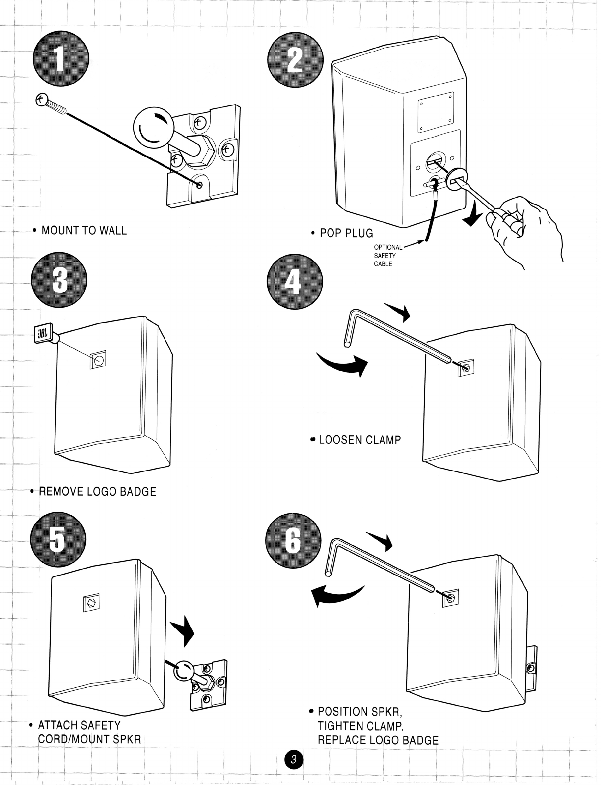
INSTALLATION
Installing with the
InvisiBall
Mounting System
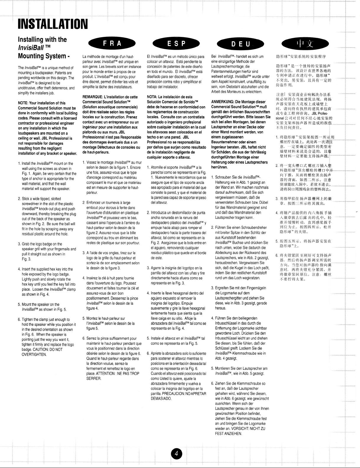
The InvisiBalfM is a unique method of
mounting a loudspeaker. Patents are
pending worldwide on this design. The
lnvisiBalfM is designed to be
unobtrusive, offer theft deterrence, and
simplify the installers job.
NOTE: Your installation of this
Commercial Sound Solution must be
done in conformity with local building
codes. Please consult with a licensed
contractor or professional engineer
on any installation in which the
loudspeakers are mounted on a
ceiling or wall. JBL Professional is
not responsible for damages
resulting from the negligent
installation of any bracket or speaker.
1.
Install the lnvisiBalfM mount on the
wall using the screws as shown in
Fig.
type of anchor is appropriate for the
wall material, and that the wall
material will support the speaker.
2.
Stick a wide tipped, slotted
screwdriver in the slot of the plastic
InvisiBalfM knock-out plug and push
downward, thereby breaking the plug
out of the back of the speaker as
shown in Fig.
fit in the hole by scraping away any
residual plastic around the hole.
3.
Grab the logo badge on the
speaker grill with your fingernails and
pull it straight out as shown in
Fig.
4.
Insert the supplied hex key into the
hole exposed by the logo badge.
Lightly push and slowly rotate the
hex key until you feel the key fall into
place. Loosen the hvisiBalfM clamp
as shown in Fig.
5.
Mount the speaker on the
lnvisiBalPM as shown in Fig.
6.
Tighten the clamp just enough to
hold the speaker while you position it
in the desired orientation as shown
in Fig.
pointing just the way you want it,
tighten it firmly and replace the logo
badge. CAUTION: DO NOT
OVERTIGHTEN.
TM
1.
Again, be vely certain that the
2.
Be sure the ball will
3.
4.
5.
6.
When the speaker is
La methode de montage d'un haut-
-
parleur avec InvisibalfM est unique en
son genre. Les brevets sont en instance
pour le monde entier
produit. L'lnvisibalfM est cony pour
dtre discret, permet dUviter les vols et
simplifie la tlche des installateurs.
REMAROUE: L'installation de cette
Commercial Sound SolutionTM
(Solution acoustique commerciale)
doit &re realis& selon les regles
locales sur la construction. Prenez
contact avec un entrepreneur ou un
ingenieur pour une installation aux
plafonds ou aux murs. JBL
Professionnal n'est pas Responsable
des dommages eventuels dus a un
montage Defectueux de consoles ou
de haut-parleurs.
1.
Vissez le montage lnvisibalfM au mur
selon le dessin de la figure
une fois, assurez-vous que le type
d'ancrage correspond au materiau
composant le mur et que ce materiau
est en mesure de supporter le hautparleur.
2.
Enfoncez un tournevis a large
embout pour ecrous a fente dans
I'ouvelture d'obturation en plastique
lnvisibalfM et poussez vers le bas,
cassant ainsi I'opercule a I'arriere du
haut-parleur selon le dessin de la
2.
Assurez-vous que la bille
figure
correspond au trou en eliminant les
restes de plastique sur son pourtour.
3.
A I'aide de vos ongles, tirez sur le
logo de la grille du haut-parleur et
sortez-le de son emplacement selon
le dessin de la figure
4.
lnserez la cle a huit pans fournie
dans I'ouverture du logo. Poussez
doucement et faites tourner la cle et
assurez-vous de son bon
positionnement. Desserrez la pince
InvisibalfM selon le dessin de la
figure
4.
5.
Montez le haut-parleur sur
I'lnvisibalfM selon le dessin de la
5.
figure
6.
Serrez la pince suffisamment pour
maintenir le haut-parleur pendant que
vous le positionnez dans la direction
desiree selon le dessin de la figure
Quand le haut-parleur regarde dans
la direction voulue, serrez-la
fermement et remettez le logo en
place. ATTENTION
SERRER.
a
:
propos de ce
1.
Encore
3.
NE PAS TROP
El InvisiBalfM es un metodo unico para
colocar un altavoz. Esta pendiente la
concesion de patentes de este diseiio
en todo el mundo. El hvisiBalfM esta
diseiiado para ser discreto, ofrecer
proteccion contra rob0 y simplificar el
trabajo del instalador.
NOTA: La instalacion de esta
Solucion Comercial de SonidoTM
debe de hacerse en conformidad con
10s reglamentos de construccion
locales. Consulte con un contratista
autorizado o ingeniero profe~ional
sobre cualquier instalacion en la cual
10s altavoces Sean colocados en el
techo o en una pared. JBL
Professional nose responsabiliza
por datios que surjan como resultado
de la instalacion negligente de
cualquier soporte o altavoz.
1.
Atomille el soporte hvisiBalfM a la
pared tal como se representaen la Fig.
1.
Nuevamente le recordamos que se
asegure que el tip0 de soporte ancla
sea apropiado para el material del que
consiste la pared, y que el material de
la pared sea capaz desoportar el peso
del altavoz.
2.
lntroduzca un destornillador de punta
ancha ranurada en la ranura del
destapadero plastico del hvisiBalfM y
empuje hacia abajo para romper el
destapadero hacia la parte trasera del
altavoz, tal como se representa en la
2.
Aseglirese que la bola entre en
Fig.
el agujero, removiendo cualquier
residuo plastico que quede en el borde
de este.
3.
Agarre la insignia del logotipo en la
parrilla del altavoz con las uiias y tire
directamente hacia afuera como se
representa en la Fig.
4.
lnserte la Have hexagonal dentro del
agujero expuesto al remover la
insignia del logotipo. Empuje
suavemente y gire la llave hexagonal
lentamente hasta que sienta que la
llave caiga en su sitio. Afloje la
abrazadera del hvisiBalfM tal como se
representa en la Fig.
5.
lnstale el altavoz en el hvisiBalfM tal
como se representa en la Fig.
6.
Apriete la abrazadera solo lo suficiente
6.
para sostener el altavoz mientras lo
posiciona en la orientacion deseada tal
como se representa en la Fig.
Cuando el altavoz este posicionado tal
como Usted lo quiere, ajuste la
abrazadera firmemente y vuelva a
colocar la insignia del logotipo en la
parrilla. PRECAUCION: NOAPRETAR
DEMASIADO.
3.
4.
Bei InvisiBalfM- handelt es sich um
eine einzigartige Methode der
Lautsprechermontage; die
Patentanmeldungen
weltweit erfolgt. hvisiBalfM wurde unter
dem Aspekt konstruiert, unauffallig zu
sein, vom Diebstahl abzuhalten und die
Arbeit des Monteurs zu erleichtern.
ANMERKUNG: Die Montage dieser
Commercial Sound SolutionrM mu8
geman den ortlichen Bauvorschriften
durchgefuhrt werden. Bitte lassen Sie
sich bei allen Montagen, bei denen
Lautsprecher an einer Decke oder
einer Wand montiert werden, von
einem zugelassenen
Bauunternehmer oder einem
lngenieur beraten. JBL haftet nicht
fur Schaden, die aus der
durchgefuhrten Montage einer
Halterung oder eines Lautsprechers
herruhren.
1.
Schrauben Sie die InvislBalPMHalterung wie in Abb.
der Wand an. Wir machen nochmals
darauf aufmerksam, daO Sie sich
vergewissern mussen, daO die
verwendeten Schrauben bzw. Dubel
fur das Wandmaterial geeignet sind
und daO das Wandmaterial den
Lautsprecher tragen kann.
2.
Fuhren Sie einen Schraubendreher
mit breiter Spitze in den Schlitz der
aus Kunststoff bestehenden
hvisiBalfM Buchse und drucken Sie
nach unten, wobei Sie dadurch die
Abdeckung aus der Ruckwand des
Lautsprechers, wie in Abb.
herausbrechen. Vergewissern Sie
sich, daO die Kugel in das Loch paOt,
indem Sie den restlichen Kunststoff
rund um das Loch wegkratzen.
3.
Ergreifen Sie mit den Fingemageln
die Logomarke auf dem
Lautsprechergitter und ziehen Sie
diese, wie in Abb.
heraus.
4.
Fuhren Sie den beiliegenden
lnbusschlussel in das durch die
Entfemung der Logomarke sichtbar
gewordene Loch. Drucken Sie den
5.
6.
lnbusschlussel leicht an und drehen
Sie diesen, bis Sie fuhlen, daO der
Schlussel greift. Lockem Sie die
InvisiBalfM-Klemmschraube
Abb.
4
gezeigt.
5.
Montieren Sie den Lautsprecher am
hvisiBalfM, wie in Abb.
6.
Ziehen Sie die Klemmschraube so
fest an, daO der Lautsprecher
gehalten wird, wahrend Sie diesen,
6
wie in Abb.
ausrichten. Wenn sich der
Lautsprecher genau in der von lhnen
gewunschten Position befindet,
ziehen Sie die Klemmschraube fest
an und bringen Sie die Logomarke
wieder an. VORSICHT NlCHT ZU
FEST ANZIEHEN.
gezeigt, wie gewunscht
hielfur sind
fahrltissig
1
gezeigt an
2
gezeigt,
3
gezeigt, gerade
wie in
5
gezeigt.
Page 6

Input
-
Simply connect the amplifier's
directly to the red
(+)
and black
the enclosure (see diag.
-
Since the loudspeakers have a rated
ce of
8R
each, more than one speaker
1).
"+"
(-)
input jacks on the back of
usually be wired to one amplifier channel (see
See "amplifier impedance load" below.)
and
"-"
outputs
MPLlFlER
n
EACH
CHANNEL
4R
PER CHANNEL
ating the Subwoofer SB-2
Subwoofer as an
8R
loudspeaker and wire into
-
Treat each input
INPUT
RIGHT
lete system accordingly (see diag. 3). (See
er impedance load" below.)
Amplifier Impedance Load
a
-
When you connect more than one loudspeaker system to an amplifier channel, either by
AMPLIFIER
R
EACH CHANNEL
40
PER CtiANNEL
twisting two wires together at the speaker location or via individual "home runs" from the speakers to the amplifier, the load
impedance to the amplifier drops. To find the maximum number of
channel of your power amplifier, divide
speaker
+
4R
amp's minimum impedance
8
by the amplifier's minimum impedance load recommendation (e.g.
=
2
speakers per channel, see diags.
8R
speakers that can be wired in parallel to each
8R
2
&
3).
Control@
Page 7

INPUT
LEFT
--
RIGHT
AMPLIFIER
4Cl
6.n
EACH CHANNEL
PER CHANNEL
SerieslParallel - It is possible to utilize various serieslparallel 'hook-up' topologies to increase the number of loudspea
driven on an amplifier. See diag. 4 for one example of a serieslparallel hook-up topology.
Note: Mismatching the speaker impedance such that it is below the minimum impedance rating of an amplifier channel
2
damage the amplifier and degrade performance. If the application requires more than
speakers per amplifier channel
wired in parallel, a distributed line system should be considered. Also check your amplifier's manual for cautions and
recommendations.
Importance of Correct Polarity ("In-Phaselout-of-Phase")
-
When two loudspeakers are wired with opposite polarity
("out-of-phase") relative to each other, the low frequencies of the loudspeakers cancel each other, even though the speak-
--
ers are "working hard." Trying to correct the lack of bass with an equalizer can damage your loudspeakers
equalization
cannot correct polarity errors. Always make sure multiple speakers are connected in proper polarity. (See "Poor Low
Frequency Output" in the Troubleshooting section for instructions about how to detect and correct polarity problems.)
-
Distributed Line Systems (Control
in 7011 00 volt autoformers.
These types of speakers need a line distribution amplifier.
ers, simply connect the amplifier's
"t"
"AT"
models) - The Control@ 25AT & Control@ 28AT models come equipped with
As with conventional 8Q s
and
"-"
outputs directly to the red (t) and black
(-)
input jacks on the back of the
enclosure. Set the autoformer tap to your desired wattage. Unlike conventional 8fl speakers, you may connect as many
"AT" speakers as you'd like to one amplifier channel
amplifiers power rating
(see diag. 5).
(e.g. A 100 watt amplifier channel could safely drive 13 speakers set to 7.5 watts each, i.e. 13 x 7.5
providing that all the speaker taps do not add up to
=
97.5 < 100) A
more
than the
conservative rule-of-thumb is to try to keep the sum of the speaker loads (watts) under 314 of the power amp rating (e.g. A
100 watt amplifier channel will then drive 10 speaker set to 7.5 watts each, i.e. 10 x 7.5
=
75 watts).
Page 8

because of differences in the acoustical setting. Since an enclosed room
presents acoustical boundaries (walls, floors
&
ceilings), sound indoors
exhibits quite complex behavior. Each time a sound wave strikes a boundary,
part of the wave's energy is reflected and part is absorbed (see diag.
Reflection & absorption are dependent on the freauencv of the sound wave
'
1).
and the angle at which it strikes the boundary.
orption
-
When designing your system, note that
e and furniture absorb sound, while glass and tile
t
sound. The percentage of energy that a boundary
orbs is often expressed by an
absorption coefficient
of
boundarv material, where an absorlstion coefficient of
Reverberation
-
Reverberation
is the reflected sound
waves continuing to bounce between the boundaries, losing
energy with each reflection. When sound strikes the reflective boundaries of a room, after a time the room is filled with
random reflected sound waves. Music and speech become
unintelligible (see diag. 3A). To minimize reverberation in a
highly reverberant room, it is advisable to install
more
speakers, and play them at lower levels (see diag. 3B).
Page 9

HORIZONTAL VERTICAL
frequencies go where you point them.
Simply aim the center axis of the
speaker into the plane slightly above
the listening area. The 90" x 90"
horns of the Control@ Contractor
Series disperse the high notes by
off axis in every direction. For large or
unusually shaped rooms, divide the
area into zones and let the horn
patterns dictate the spacing between
the speakers (see diag.
5)-
45"
AMPLIFIER
TYPICAL DAISY CHAIN CONFIGURATION
TYPICAL "HOME RUN" CONFIGURATION
-
f
Boundary Loading
without taxing the amplifier. It is also possible to make a system
sound too "muddy", so use caution. If you move the speaker from
open space to a wall, bass notes will increase by
2
move it to a
for a three boundary corner! (see diag.
boundary corner, another t3dB
-
This is a good trick for increasing bass
+
3dB. If you
...
and another t3dB
4).
Daisy Chaining
to run wires from the amp to a speaker, then from that
speaker to another (see diag. 6A).
Home
Runs
listening position, "home runs" are best, from the amplifier
directly to each speaker (see diag. 6B).
-
It is most common, easiest, and cheapest
-
If you desire true stereo
L & R
from each
Page 10

Wind - Wind gives the illusion that a sound is coming from
a different direction than it really is. This creates a
propagation vector
with the wind it tends to refract downward, and against the
wind refract upwards (see diag. 2), (*refraction is the term
used to describe the bending of sound).
(see diag. 1). When sound propagates
ISS
WlND
CROSS
re<ant
WlND
SOU
-
From the speakers to our ears
background SPL of about 70dB
mind the Inverse Square Law, which states that in a free field with no
walls, floor, or ceiling, the intensity of sound decreases with the
square of the distance. For example when you double the distance
between the speaker and your listener's ear, the SPL decreases by
6dB (i.e. If a speaker's output is 100dB SPL at 10 feet away, at 20
feet away the SPL is decreased to 94dB.) Don't forget, a
will sound "half as loud".
Since you usually want a target
-
80dB to your listeners, keep in
1
OdB drop
PROPAGATION
VECTOR
'
CROSS
WlND
Temperature - Temperature differences also have a small
effect'on sound propagation. Hot air is less dense than cold.
travels faster in a less dense medium and therefore
up as air gets warmer, and slows down as air gets
Page 11

It is important to understand that just as the propagation of sound
outdoors is effected by its surroundings so is the propagation of sound
indoors. Some of these environmental factors exist in both cases,
such as reflective surfaces and absorbant materials, but there are a
few unique effects that may need to be considered. The factors
described on this
tion to deviate from tjhe
Daae can cause the behavior of an outdoor installa-
Inverse
Square
Law. Remember not all
frequencies of the propagated sound will be affected uniformly.
JUNGLE
l
Humidity - Because water vapor is lighter than air, humid
is less dense than dry air and, therefore absorbs less
acoustical energy than dry air particularly at frequencies
above 2kHz. To labour the point, a speaker mounted on a
tree in a jungle will project high frequency sound further than
the same speaker mounted on a cactus in the desert (see
5
&
diags.
6).
Painting the Speakers
-
The polystyrene speaker enclosures of the Controls 23,
Control@ 25,
&
Control@ 28 can be painted to match almost
any decor. The vinyl skin of the Controls SB-2 subwoofer can
also be painted.
l
Remove the grilles. Mask the woofers, tweeters, & ports on
the front, and the wire terminals on the back, being careful
that no tape comes in direct contact with the drivers.
l
Clean the enclosures with a light solvent such as mineral
spirits by rubbing the components with a lightly dampened
cloth. Do not, however, use abrasives such as sandpaper or
steel wool on the enclosures. Nor should you use gasoline
kerosene, acetone,
MEK,
paint thinner, harsh detergents o
other chemicals. Use of these cleaners may result in perm
nent damage to the enclosures.
After cleaning, apply two or more thin coats of either latex or
oil-based paints. Latex paints will adhere better if an oil-
based primer is used first. Application can be by rolling,
brushing, or spraying.
The grilles require masking of the logo plug, then spray
painting. If the grill is rolled or brush painted, the mesh may
become clogged with paint, and poor sound quality may
result.
-AAA
*"
"A
'
l
The
InvisiBalFM
mount may also be painted, but because it
Page 12

RODUCT
A A
Your Control Contractor system has been designed and manufactured for durability and reliable service. As with any fine
product, proper maintenance and care will extend the life of your system.
You can expect your system components to perform indefinitely if you use them within their stated limits for power handling,
and see that they are not abused.
CARE
MAINTENANCE
Always protect the loudspeakers from over-excursion caused by strong subsonic signals (signals below
amplifier has a "low cut" or "high pass" switch, engage it.
Please note that although the C23, C25 and C28 are designed to be weather resistant they are NOT WEATHERPROOF.
Insect screens have been included in the design of the low frequency vents. It may be wise to periodically check and clear
AA A
any debris collected, to ensure proper operation of the vent.
is not unheard of for rodents to eat and destroy foam. It is recommended that the foam surrounding the SB-2 subwoofer
osure be treated with a rodent repellent, especially in an installation that may be subject to the occasional rodent
ation.
30Hz).
If your
JBL LIMITED WARRANTY
Control Contractor products are designed and backed by JBL, the world leader in sound reinforcement. For complete JBL
warranty information within the United States please refer to the warranty card enclosed with your Control Contractor
product. In other areas of the world please contact your local JBL distributor.
Page 13

If none of the suggestions below solve your problem, contact your nearest
JBL
service center or
JBL
distributor.
Problem
1.
No Output.
2.
Questionable or
intermittent output
such as crackling.
Possible
Causekl
Speaker
Cable(s)
Amplifier
A poor
connection
Action
Replace the cable(s) connecting the loudspeaker system
and amplifier.
Make sure the amplifier channel is being fed an input
signal (preferably via a "signal input" indicator on th
amp).
Check that the amplifier channel's volume control is
turned up.
Connect the speaker and cable which had no output
another amplifier channel, making sure an input sign
fed to the new amp channel. If you then get output, th
problem was the amplifier channel. If not, then the
problem may be in the cable or speaker.
Check all cabling for proper connector contact since a
bad connection can result in intermittent contact or
dramatically increased resistance which, in turn, can
cause reduced output or noises unrelated to the signal.
""""
"""""
"",
3.
Constant noise such as
buzzing, hissing, or
the humming sound.
A faulty
electronic
device in the
signal chain
Poor system
grounding
4.
Poor low frequency Out-of-Polarity
output. Hookup
between multiple
speakers
Since loudspeakers cannot generate these sounds b
themselves, you may have a faulty electronic device
the signal chain.
a
Check and correct the system grounding, as required.
When two speakers are hooked up out-of-polarity ("out
of-phase"), the low frequencies cancel each other out.
Try reversing the polarity of one of the speakers eithe
by turning around a dual-banana plug at the amplifier
by reversing the tiplsleeve leads on the jack. Whicheve
Page 14
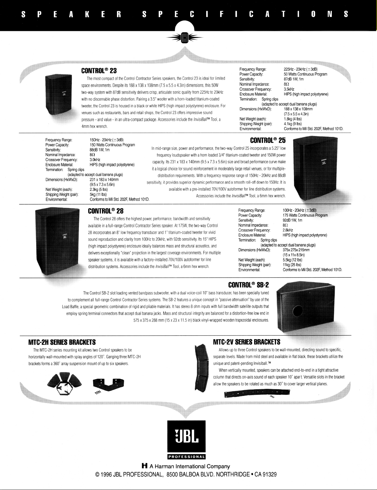
CONTROL@
space environments. Despite its 188
two-way system with 87dB sensitivity delivers crisp, articulate sonic quality from 225Hz to 2OkHz
with no discernable phase distortion. Pairing a 3
tweeter, the Control 23 is housed in a black or white HlPS (high impact polystyrene) enclosure. For
venues such as restaurants, bars and retail shops, the Control 23 offers impressive sound
pressure
4mm hex wrench.
Frequency Range:
Power Capacity:
Sensitivrty:
Nominal Impedance:
Crossover Frequency:
Enclosure Material:
Termination: Spring clips
Dimensions (HxWxD):
Net
Shipping Weight (pair):
Environment4
(adapted to
Weight (each):
23
The most compact of the Control Contractor Series speakers, the Control 23 is ideal for limited
x
138 x 108mm (7 5 x 5 5 x 4.3in) dimensions, this 50W
5"
woofer with a horn-loaded titanium-coated
-
and value - in an ultra-compact package. Accessories include the
150Hz
-
2OkHz (23dB)
150 Watts Continuous Program
88dBIW,lm
8R
3.OkHz
HlPS (high impact polystyrene)
accept dual banana plugs)
231 x183x140mm
(9.5
x 7.3 x 5.6in)
2.3kg (5 Ibs)
5kg
(H
Ibs)
Conforms to Mil Std.
2MF,
Method
In mid-range size, power and performance, the two-way Control 25 incorporates a 5.25" low
frequency loudspeaker with a horn loaded 314' titanium-coated tweeter and 150W power
capacity Its 231
it a logical choice lor sound reinforcement in moderately large retail venues, or for multiple-
distribution requirements. With a frequency response range of
sensitivity, it provides superior dynamic performance and
101D.
available with a pre-installed 70Vl100V autoformer for line distribution systems.
hvisiBalPM
Tool, a
x
183 x l40mm (9.5 x 7.3 x 5.6in) size and broad performance curve make
Accessories include the
Frequency Range:
Power Capacity:
&flsf~ity: 87dB 1 W, lm
Nominal lmpedam: 8R
Crossover Frequency: 3.5kHz
Enclosure Material: HIPS (hgh impact polystyrene)
Termination: Spring clips
Dimensions (HxWxD): 188 x 138 x
Net WeigM (each): 1.8kg (4 Ibs)
Shipping Weight (pair): 4.1 kg (9 Ibs)
Environmentat Conformsto Mil Std. 202F. Method 101D.
a
smooth roll-oft down to 150Hz It is
hvisiBalP
(adapted to accept dual banana plugs)
(7.5 x 5.5 x 4.3in)
CONTROL@
-
150Hz
Tool, a 6mm hex wrench.
25
20kHz and 88dB
108mm
CONTROL@
The Control 28 offers the highest power, performance, bandwidth and sensitivity
available in a full-range Control Contractor Series speaker At 175W, the two-way Control
28 incorporates an 8" low frequency transducer and 1" titanium-coated tweeter for vivid
sound reproduction and clarityfrom 100Hz to 2OkHz, with 92db sensitivity. Its 15" HlPS
(high impact polystyrene) enclosure ideally balances mass and structural acoustics, and
delivers exceptionally "clean" projection in the largest coverage environments. For multiple
speaker systems, it is available with a factory-installed
distribution systems. Accessories include the
The Control SB-2 slot loading vented bandpass subwoofer, with a dual voice-coil 10 bass transducer, has been specially tuned
to complement all full-range Control Contractor Series systems. The SB-2 features a unique concept in "passive attenuation" by use of the
Load Baffle, a special geometric combination of rigid and pliable materials. It has stereo
employ spring terminal connectors that accept dual banana jacks. Mass and structural integrity are balanced for a distortion-free low end in
The MTC-2H series mountng k~t allows two Control speakers to be
horizontally wall-mounted with splay angles of 120". Ganging three MTC-2H
brackets forms a 360" array suspension mount of up to six speakers.
28
575 x 375
Frequency Range:
Power Capacity:
Sensitivity:
Nominal Impedance:
Crossover Frequency:
Enclosure Material:
Terminatim: Spring clips
Dimensions (HxWxD):
70Vl100V autoformer for line
hvisiBalPM
Tool, a 6mm hex wrench.
Net Weight (each):
Shipping Weight (pair):
Environmental:
CONTROL@
8
ohm inputs with full bandwidth satellite outputs that
x
288 mm (15 x 23 x 11.5 in) black vinyl-wrapped wooden trapezoidal enclosures.
Allows up to three Control speakers to be wall-mounted,
unique and patent-pending In~isiball.~~
When vertically mounted, speakers can be attached end-to-end in a tight attractive
(adapted to
SB-2
92dB IW, Im
8n
2.8kHz
HlPS (high impact polystyrene)
accept dual banana plugs)
375x 275x 21 5mm
(15 x 11x 8.5in)
5.5kg (12 Ibs)
11 kg
(25
1s)
Confonnsto Mil Std.
ver larger vertical planes.
2MF,
Method 101D.
H
A
Harman International Company
0
1996 JBL PROFESSIONAL,
8500
BALBOA
BLVD.
NORTHRIDGE CA 91 329
 Loading...