

PSW-D110/DPS-10
Powered Subwoofer
SERVICE MANUAL
JBL Consumer Products Inc.
250 Crossways Park Drive
Woodbury, N.Y. 11797
1-800-336-4JBL in the USA
A Harman International Company
Rev C 8/2000

Amplifier/Subwoofer PSW-D110/DPS-10
SAFETY INFORMATION
Warning
Any person performing service of this unit will be exposed to
hazardous voltages and the risk of electric shock. It is
assumed that any person who removes the amplifier from
this cabinet has been properly trained in protecting against
avoidable injury and shock. Therefore, any service
procedures are to be performed by qualified service
personal ONLY!
Caution
This unit does not have a power switch. Hazardous
voltages are present within the unit whenever it is
plugged in.
Before the amplifier is plugged in, be sure its rated voltage
corresponds to the voltage of the AC power source to be
used. Incorrect voltage could cause damage to the
amplifier when the AC power cord is plugged in. Do not
exceed rated voltage by more than 10%: operation below
90% of rated voltage will cause poor performance or may
shut the unit off.
Leakage/Resistance Check
Before returning the unit to the customer, perform a leakage
or resistance test as follows:
Leakage Current. Note there is no power switch on this unit.
When the power plug is plugged in, the unit is live. Connect
the unit to its rated power source. Using an ammeter,
measure the current between the neutral side of the AC
supply and chassis ground of the unit under test. if leakage
current exceeds 0.5mA, the unit is defective. Reverse the
polarity of the AC supply and repeat.
Resistance. Measure the resistance from either side of the
line cord to chassis ground. If it is less than 500k ohms, the
unit is defective.
WARNING! DO NOT return the unit to the customer if it fails
one of these tests until the problem is located and corrected.
Critical Components
All components identified with the IEC symbol
in the parts list and the schematic diagram
designate components in which safety can be
of special significance when replacing a
component identified with . Use only the
replacement parts designated in the parts list or parts with
the same rating of resistance, wattage or voltage.
List of Safety Components Requiring
Exact Replacements
F1 Fuse SLO BLO 1.25A 250V UL approved
PWRCORD SPT-2 or better with polarized plug, UL
approved wired with the hot side to fused
side. Use with factory replacement panel
strain relief only.
TRX1 Transformer. Use only factory replacement.
DBR Bridge diode. Use only factory replacement.
C1, 2 4700uF, 50V electrolytic filter caps. Be sure
replacement part is at least the same
working voltage and capacitance rating.
Also the lead spacing is important.
Incorrect spacing may cause premature
failure due to internal cabinet pressure and
vibration.
C6 10uF 50V electrolytic radial
See Page 14 Service Bulletin
S52AMI Power output module. Use only factory
replacement
Faceplate Faceplate. Use only factory replacement
Air leak cover Use only factory replacement
CMC1 Use only factory replacement
L1 Use only factory replacement
Fuse PCB Use only factory replacement
Main PCB Use only factory replacement
2

Amplifier/Subwoofer PSW-D110/DPS-10
TABLE OF CONTENTS
SAFETY INFORMATION ...............................................2
TABLE OF CONTENTS .................................................3
GENERAL SPECIFICATIONS .......................................3
DETAILED SPECIFICATIONS.......................................4
PSW-D110/DPS-10 CONTROLS AND
THEIR FUNCTION.........................................................6
OPERATION...................................................................7
SPEAKER CONNECTIONS...........................................8
TROUBLESHOOTING ...................................................9
PSW-D110/DPS-10 TEST SET UP
AND PROCEDURE......................................................10
PSW-D110/DPS-10 POWER AMP
TEST PROCEDURE and FLOW CHART....................11
SERVICE BULLETIN JBL9902 REV1 - MAY 1999 ..........14
SERVICE BULLETIN JBL9903 - APRIL 1999 ..................15
SERVICE BULLETIN JBL2000-01 - JANUARY 2000.......16
CABINET EXPLODED VIEWS ....................................17
AMPLIFIER EXPLODED VIEW ...................................18
PSW-D110/DPS-10 MECHANICAL PARTS LIST.......19
PACKING EXPLODED VIEWS....................................20
PSW-D110/DPS-10 Version 3.53 PCB
(Component Side) ........................................................21
PSW-D110/DPS-10 Version 3.53 PCB
(Solder Side) ................................................................22
PSW-D110/DPS-10 Version 3.93 PCB
(Component Side) ........................................................23
PSW-D110/DPS-10 Version 3.93 PCB
(Solder Side) ................................................................24
PSW-D110/DPS-10 ELECTRICAL PARTS LIST ........25
PSW-D110/DPS-10 INTEGRATED CIRCUITS ...........26
PWS-D110/DPS-10 SCHEMATIC 1 of 2.....................27
PWS-D110/DPS-10 SCHEMATIC 2 of 2.....................28
GENERAL SPECIFICATIONS
Amplifier Power (RMS) ........150watts
Driver 10" .............High-Polymer Laminate
Inputs ...............Line Level and Speaker Level
Outputs ..............Line Level and Speaker Level
Low-Pass Frequency ........Continuously variable from 60Hz – 180Hz
High-Pass Frequency ........Continuously variable from 60Hz – 180Hz
when using line-level inputs
180Hz when using speaker-level inputs
Frequency Response ........30Hz – low-pass crossover setting
PSW-D110 DPS10
Dimensions (HxWxD).......15-3/8 x 15-3/8 x 17" 18-1/16 x 14-7/8 x 15-7/8"
(391 x 391 x 432mm) (459 x 378 x 403mm)
Weight ...............33lbs/15 kg 30 lbs/13.6 kg
3
Amplifier/Subwoofer PSW-D110/DPS-10
DETAILED SPECIFICATIONS
LINE VOLTAGE
US 120vac/60Hz
EU 230vac/50-60Hz
Parameter Specification Unit Conditions Notes
Amp Section
Type (Class AB, D, other)
Load Impedance
(speaker)
Rated Output Power
Yes/No
Yes
Yes
D
4
150
75
THD@ Rated Power
THD @ 1 Watt
DC Offset
Damping factor
Input Sensitivity
Input Frequency
Line Input
Speaker/Hi Level Input
0.1
0.1
2
>200
50
110
2.7
Hi/Lo Line Unit Notes
108-132 Vrms Normal Operation
207-264 Vrms Normal operation, MOMS required
Class D Preferred...Sink required for Class AB
Ohms Nominal Z-curve required
Watts 1 input driven Peak power
Watts 1 input driven RMS
% 22k filter 75w (Power Bandwidth 30-100Hz)
% 22k filter
mV-DC @ Speaker Outputs
DF
Hz Nominal Freq. 1 input driven
mVrms To Rated Power/ Vol @ Max 1 input driven
Vrms To Rated Power/ Vol @ Max 1 input driven: AP sourceZ=25ohms
Signal to Noise
SNR-A-Weighted
SNR-unweighted
SNR rel. 1W-unweighted
Residual Noise Floor
Residual Noise Floor
Input Impedance
Line Input
Speaker/Hi Level Input
Filters 0dBr = 1w @ 50Hz
Low Pass (fixed or
variable)
Low Pass filter (point or
range)
Slope
Q
Subsonic filter (HPF)
Slope
Q
100
75
65
2
1.5
10k
200
Variable
60-120
18
1
25
12
1
dBA
dBr relative to 75w power 22k filter
dBr relative to 1W Output 22k filter
mVrms Volume @max, using RMS reading DMM/VOM (or A/P)
mVrms(max) Volume @max, w/ A/P Swept Bandpass Measurement (Line freq.+ harmonics)
ohms Nominal
ohms Nominal
Hz -3dB Point
dB/Octave
Damping
Hz -3dB Point
dB/Octave
Damping
relative to 75w power
A-Weighting filter
4
Amplifier/Subwoofer PSW-D110/DPS-10
Limiter (yes/no)
THD at Max. Output
Power
Features
Phase Switch (yes/no)
Volume pot Taper
(lin/log)
Input Configuration —
Line In
(L,C,R,AC3,Mono)
Line Outputs (L,C,R)
Line-Out Adj. X-over
Spkr/Hi Level In
(L,C,R,mono)
Spkr Out: Hi Pass Filter
Signal-Present LED Bi-Color LED (green=signal/ red=no signal)
Signal-Present Input
Freq.
Signal-Present Level
Signal-Present
Bandwidth
Signal-Present Turn-on
time
Auto Mute/ Turn-OFF
Time
Yes
10
yes
linear
L,R
L,R
130-240
L,R
100
100
2
1k
1
15
% Maximum Output Power Maximum THD as a result of limiting.
—
—
—
— Buffered Output / Pre-Volume control
Hz
—
Hz
Hz Nominal 200uF Series Cap on PCB
mV
Hz
sec. Amp connected and AC on, then input signal applied
min.
Enabled w/Line/Spkr Input
Select Switch
Var-HPF (Pot CCW and CW
positions)
Enabled w/Line/Spkr Input
Select Switch
8 ohm Satellite: 6dB/oct
passive xover
100Hz into Line Input w/ 1 ch.
driven
Signal-Present-LPF for noise
immunity
T before muting, after signal
is removed
Rear panel Variable xover
Driven from zero ohms source impedance
Power on Delay time
Transients/Pops
Signal-Present Transient
Turn-on Transient
Turn-off Transient
Efficiency
Stand-by Input Power
AC Power Cons.@1W
Power Cons.@rated
power
Efficiency
Protection
Short Circuit Protection yes Direct short at output
Line Fuse Rating 1.25 Amps Type-T or Slo Blo
3
5
500
500
17
18
107
70.09%
sec. AC Power Applied
mV-peak @ Speaker Outputs
mV-peak @ Speaker Outputs AC Line cycled from OFF to ON
mV-peak @ Speaker Outputs AC Line cycled from ON to OFF
Watts @ nom. line voltage
Watts @ nom. line voltage
Watts @ nom. line voltage
% Relative to 75w output
5
Amplifier/Subwoofer PSW-D110/DPS-10
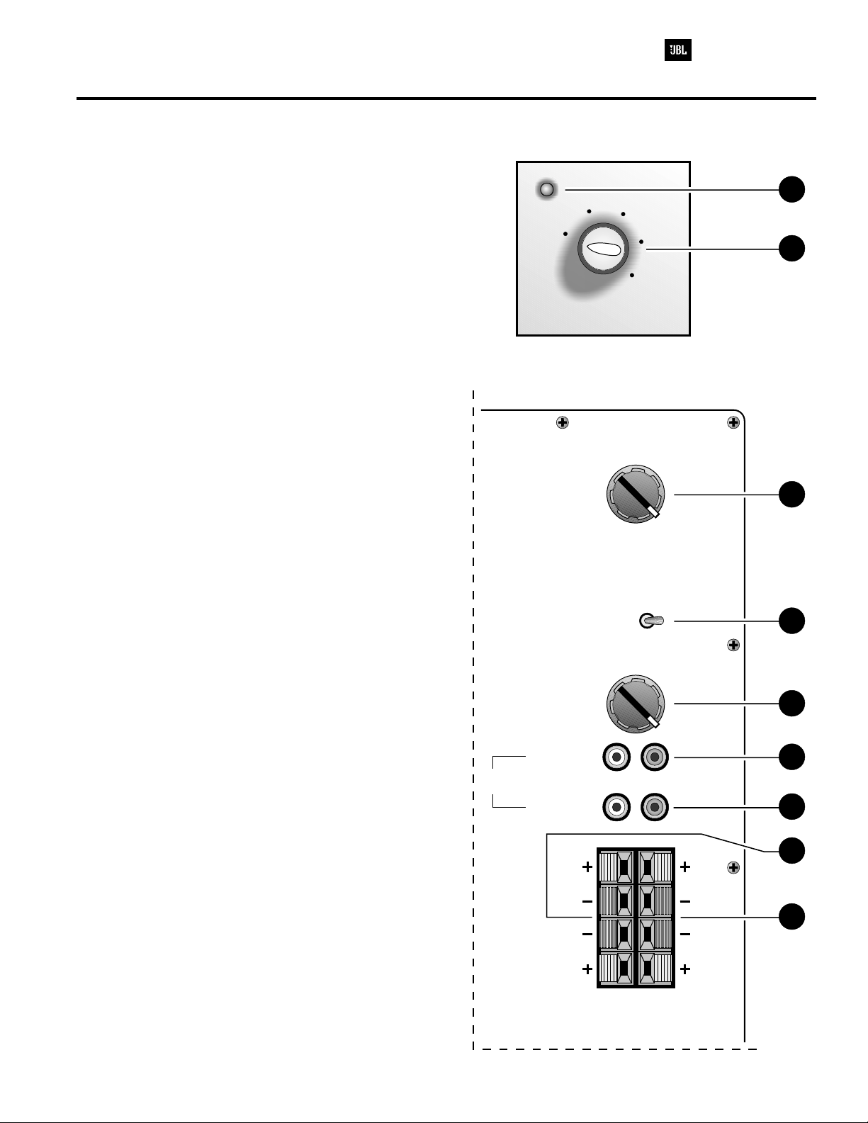
PSW-D110/DPS-10 CONTROLS AND THEIR FUNCTION
1. Power - (PSW-D110 ONLY) This light will be RED
when the unit is plugged in and not receiving a signal;
when the PSW-D110 receives a signal, the light will cycle
to GREEN. If no signal is received after 10 – 15 minutes
the light will cycle back to RED (standby) until a signal is
present again.
2. Level Control - The subwoofer Level Control,
(PSW-D110, located on the front panel, DPS-10, on the
rear panel) adjusts the volume of the subwoofer relative
to the rest of the system.
3. High Pass Control - Controls the the roll-off point of
the highest frequency the subwoofer will produce.
4. Phase Switch - Changes the subwoofer's output to be
in phase or 180 degrees out of phase with the program
material.
5. Low Pass Control - Controls the roll-off point of the
lowest frequency produced at the High Pass Output
Jacks.
6. High Pass Output - When using the Line-Level Input
jacks, these are connected to an external power amplifier
or receiver to power the main loudspeakers with a high
pass filter if desired.
Front Panel ( only)PSW-D110
min
max
Rear Panel
120
High
Pass
90
60
150
180
1
2
3
7. Line Input - Main Input connection to subwoofer
(preferred).
8. Speaker In Jacks - Main Input connection to
subwoofer when line level, subwoofer, or pre-amp output
connectors are not availible, or when a high pass filter
(set at 180Hz) to main loudspeakers is desired through
the Speaker Output Jacks.
9. Speaker Out Jacks - Connected to main loudspeakers
when the Speaker Input Jacks are used.
Line
Phase
Low
Pass
High Pass
Output
Input
RR
LL
SPKR
IN
90
60
180o0
120
RL
o
4
150
5
180
6
7
8
9
SPKR
OUT
6

Amplifier/Subwoofer PSW-D110/DPS-10
OPERATION
Crossover Adjustments
High-Pass Control
• This control is only active if you are using the hook-up
method described in detail on page 8, Figure 3. The
High-Pass control determines the frequency at which the
main speakers will start reproducing sounds. If your main
speakers can comfortably reproduce some low-frequency
sounds, also set this control to a lower frequency setting,
between 50Hz – 100Hz. This will concentrate the
subwoofer’s efforts to the ultradeep bass sounds, while your
main speakers continue to reproduce the mid-bass
information. If you are using smaller bookshelf speakers
that do not extend to the lower bass frequencies, set the
high-pass crossover control to a higher setting, between
125Hz – 180Hz. With this setting, your main speakers will
not have the burden of reproducing any low-frequency
sounds.
Final adjustment and blending of the low-pass and
high-pass controls may evolve over several listening
sessions. A good starting point would be to set both the lowand high-pass controls to the same frequency and adjust
from that point.
Low-Pass Control
The Low-Pass control determines the highest frequency at
which the subwoofer reproduces sounds. If your main
speakers can comfortably reproduce some low-frequency
sounds, set this control to a lower frequency setting,
between 50Hz – 100Hz. This will concentrate the
subwoofer’s efforts on the ultradeep bass sounds required
by today’s films and music. If you are using smaller
bookshelf speakers that do not extend to the lower bass
frequencies, set the low-pass crossover control to a higher
setting, between 120Hz – 180Hz.
Phase
Phase Control
The Phase Control determines whether the subwoofer
speaker’s piston-like action moves in and out with the main
speakers, 0° , or opposite the main speakers, 180° . There is
no correct or incorrect setting. Proper phase adjustment
depends on several variables such as room size, subwoofer
placement and listener position. Adjust the phase switch to
maximize bass output at the listening position.
Remember, every system, room and listener is different.
There are no right or wrong settings; any setting you choose
will result in excellent performance. Should you decide to
fine-tune your system for optimum performance, be patient
and trust your ears. It will be worth the effort involved to fully
“tweak” your system.
7
Amplifier/Subwoofer PSW-D110/DPS-10
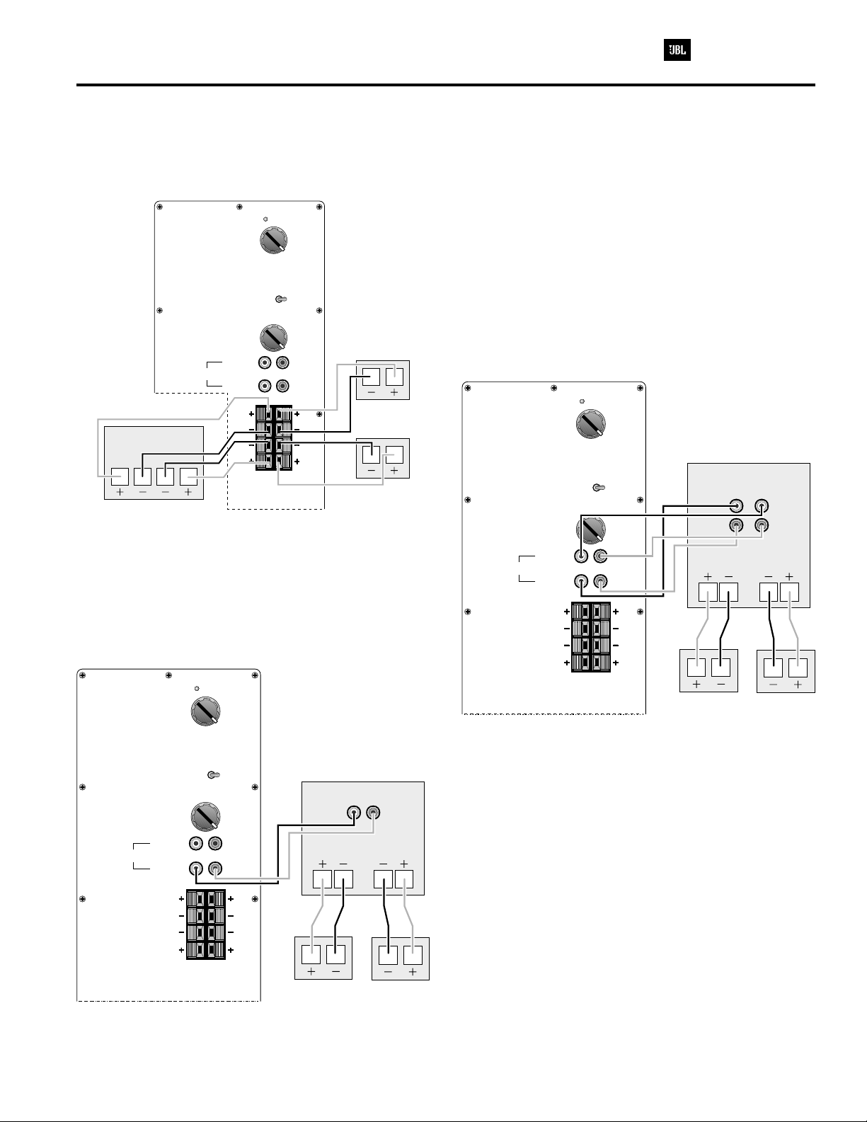
SPEAKER CONNECTIONS
NOTE: The rear plate for the PSW-D110 is shown, which has the level control on the front panel. The DPS-10 has this
level control on the rear panel (amplifier)
Figure 1
Power
120
90
High
Pass
Phase
Low
Pass
High Pass
Output
Line
Input
RECEIVER/AMPLIFIER
SPEAKER OUTPUT
RIGHT
LEFT
SPKR
1) If your receiver/amplifier has no subwoofer outputs or
preamp outputs for the left and right channels. See Figure 1.
150
180
60
o
180o0
120
90
150
180
60
RL
RR
LL
SPKR
OUT
IN
RIGHT
SPEAKER
LEFT
SPEAKER
2) If your receiver/amplifier has subwoofer outputs or
preamp output jacks for the left and right channels. See
Figure 2.
Note: Some receivers/amplifiers have a single (mono)
subwoofer output. In this case, it is recommended that you
use a “Y”-connector (not included) to maximize the
subwoofer’s performance.
Power
Line
High
Pass
Phase
Low
Pass
High Pass
Output
Input
120
90
150
180
60
o
180o0
120
90
150
180
60
RL
Figure 3
RECEIVER/AMPLIFIER
PRE
MAIN
OUT
IN
LEFT
RIGHT
MAIN SPEAKER OUTPUT
RIGHT
LEFT
Line
Power
120
90
High
Pass
60
Phase
Low
Pass
High Pass
Output
Input
180o0
120
90
60
RL
RR
LL
SPKR
IN
180
180
150
o
150
SPKR
OUT
Figure 2
RECEIVER/AMPLIFIER
SUBWOOFER OUT
LEFT
MAIN SPEAKER OUTPUT
RIGHT
RIGHT
LOUDSPEAKER
LOUDSPEAKER
RIGHT
LEFT
LEFT
RR
LL
SPKR
IN
SPKR
OUT
RIGHT
LOUDSPEAKER
LEFT
LOUDSPEAKER
3) If your receiver/amplifier has preamp output jacks and
main input jacks for the left and right channels or you have a
separate pre-amp/ processor and power amplifier. See
Figure 3.
This method of hookup can offer the highest level of
performance for your complete loudspeaker system. The
PSW-D110/DPS-10 incorporates a variable high-pass
crossover in addition to a variable low-pass crossover.
When hooked up as shown above, the subwoofer will limit
the low-frequency information that is returned to your
receiver/amplifier. Your receiver/amplifier does not need to
waste valuable power reproducing the low frequencies. In
addition, since no low-frequency information is being sent to
your main loudspeakers, they are able to reproduce mid and
high frequencies with greater clarity
8

Amplifier/Subwoofer PSW-D110/DPS-10
TROUBLESHOOTING
If you used the high-level (speaker) inputs and there is no
sound from any of the speakers, check the following:
• Receiver/amplifier is on and a source is playing.
• Powered subwoofer is plugged in.
• Check all wires and connections between
receiver/amplifier and speakers. Make sure all wires are
connected. Make sure none of the speaker wires are frayed,
cut or punctured.
• Review proper operation of your receiver/amplifier. If there
is low bass output, check the following:
• Make sure the connections to the left and right “Speaker
Inputs” have the correct polarity (+ and –).
• Make sure that the sub-woofer is plugged into an active
electrical outlet.
• Powered subwoofer is plugged in.
• Adjust the crossover point.
If you used the line-level inputs and there is no sound from
the subwoofer, check the following:
• Receiver/amplifier is on and a source is playing.
• Powered subwoofer is plugged in.
• Check all wires and connections between receiver/
amplifier and subwoofer. Make sure all wires are connected.
Make sure none of the wires are frayed, cut or punctured.
• Review proper operation of your receiver/amplifier.
9

Amplifier/Subwoofer PSW-D110/DPS-10
PSW-D112/DPS-12 TEST SET UP AND PROCEDURE
CD PLAYER
PRE AMP
AC VOLT METER ( 6V )
LINE LEVEL
PWS-D110
DPS-10OR
UNDER TEST
FROM
LINE-LEVEL
SOURCE
Low
Pass
High Pass
Output
Line
Input
90
60
120
150
180
RL
AMPLIFIER
RR
SPEAKER LEVEL
LL
SPEAKER
OUTPUT FROM
AMPLIFIER
General Function
UUT = Unit Under Test
1. Connect both right and left line level inputs (RCA) to signal generator and UUT. Use Y-cable if necessary from
mono source. VOLUME control should be full counterclockwise.
SPKR
IN
SPKR
OUT
2. Turn on generator, adjust to 50mV, 50 Hz.
3. Plug in UUT; red LED should be ON. Turn VOLUME control full clockwise. Low Pass control should be set fully
clockwise (180).
4. LED should turn Green; immediate bass response should be heard and felt from port tube opening.
5. Turn off generator, turn VOLUME control fully counterclockwise, disconnect RCA cables.
6. Connect one pair of speaker cables to either high level input terminal on UUT. Cables should be connected to
an integrated amplifier fed by the signal generator.
7. Turn on generator and adjust so that speaker level output is 2.0V, 50 Hz. Turn VOLUME control full clockwise.
8. Green LED should light, immediate bass response should be heard and felt from the port tube opening.
Sweep Function
1. Follow steps 1-4 above, using a sweep generator as a signal source.
2. Sweep generator from 20Hz to 300Hz. Listen to the cabinet and drivers for any rattles, clicks, buzzes or any
other noises. If any unusual noises are heard, remove driver and test.
Driver Function
1. Remove driver from cabinet; detach + and - wire clips.
2. Check DC resistance of driver; it should be 3.9 ohms.
3. Connect a pair of speaker cables to driver terminals. Cables should be connected to an integrated amplifier fed by
a signal generator and adjust so that speaker level output is 5.0V.
4. Sweep generator from 20Hz to 1kHz. Listen to driver for any rubbing, buzzing, or other unusual noises.
10

A. Power Amp Section
PSW-D110/DPS-10 TEST PROCEDURE
1. Resistance Check
2. Power Up LED RED
3. D.C. Operation
Voltage measurements (DVM)
Between +6V V+ O/P V- +15V S/D FR I/P GND -15V
And V- GND GND GND GND V- GND GND GND GND
Should be
Reading
4. Check Switching Frequency
Use scope (EITHER USES AN ISOLATION TRANSFORMER OR ATTACHES THE PROBE TIP TO SPK- and
REFERENCE LEAD TO SPK+)
-Reading 100kHz +/-10%,1Vpp
+6.2V +43.5v 0V -43.5V +15.5V +5.75V 0V 0V 0V
Resistance from O/P of the module to GND should be >10K (NO LOAD)
Resistance from V+ of the module to V- of the module should read >5k
Resistance from V+ of the module to O/P of the module should read >10K
Resistance from V- of the module to O/P of the module should read >10K
-15.5V
B. Pre Amp Section
1. Low Level Input Sensitivity
-Set up Turn level and Low-Pass Pot Fully CW
Generator set at 50mV@43Hz
Signal to Low level input
-Voltage measurements
OP AMP
U1(1) U1(8) U1(14) U1(7) U2(1) U2(7)
415mV 395mV 590mV 603mV 5.73V 5.2V 14.5V
2. High Level Input Sensitivity
-Set up Turn level and Lo Pass Pot Fully CW
Set Generator at 2.55V@43Hz
Signal to High level input
Voltage measurements 14.5V at speaker output
3. Low-Pass
Set upSet Generator at 100mV@100Hz
Signal to Low level input
Measure voltage at speaker output
Voltage measurements
Low-Pass Pot Setting Output
CW 11.1V
CCW 5.37V
SPEAKER
O/P
11

4. High-Pass
-Set up Set Generator at 100mV@at 100Hz
Signal to Low level input
Measure voltage at high-pass output
-Voltage measurement
Hi-Pass Pot Setting Output
CW 24mV
CCW 55mV
4. LED
With a 35mV input signal at a single Low level input, LED should change to green
See flow chart (following page) for detailed diagnostics.
12

PSW-D/DPS-10 POWER MODULE TESTING FLOW CHART
C
C
U
C
U
w
C
C
C
R
C
C
C
C
R
CAUTION : MODULE OUTPUT IS FLOATING AND IS NOT PROTECTED AGAINST A SHORT
START
esistance check
(no load)
between V+ V-,
V+ O/P,V- O/P
and O/P to GND
is > 5K
OK
yes
Power up with no
signal input
LED RED
TO GROUND. ALL TEST INSTRUMENTS CONNECTED TO THE OUTPUT MUST
BE FLOATING. ATTACH THE SCOPE PROBE TIP TO SPK - and REFERENCE
LEAD TO SPK+.
heck V+; V-;
+/-15V voltage
at the module
no
no
eplace
Module
OK
yes
heck 6V at the
module wrt V-
=6.2V
heck
transformer,
CMC, rectifier,
C1, C2, D9,
D10, R16 and
R17
OK
yes
Check input of
module wrt GND
= 0V D.C.
OK
yes
se scope to
check switchi4.
High-Pass
OK
no
no
no
heck fuse
transformer,
CMC, rectifier,
C1 and C2
heck C29 and
Pre-AMP
OK
yes
heck S/D volt-
age at the module
wrt V- =5.75V
OK
yes
se scope to
check O/P at
module wrt GND
90Vpp square
ave shown
OK
yes
no
no
no
heck D6, R9
and R46
heck D1, R1,
Q3, Q4, Q5,
and SCP
yes
heck L1, L2,
L3, L4, C6 and
MODULE OK
24
END
13

Amplifier/Subwoofer PSW-D110/DPS-10
SERVICE BULLETIN JBL9902 REV1 - MAY 1999
To all JBL Service Centers
Model: PSW-D110
Subject: Grille removal
When servicing the PSW-D110 subwoofer, care must be taken when removing the metal subwoofer speaker grille.
Removing the grille by grasping one grille edge and pulling it off with a hinge-like action could result in broken
grille pins.
To Remove
Place the subwoofer on a padded surface, with the grille facing upwards.
1)
Grasp the grille with both hands in two of the opposite cut-outs between the grille and the cabinet.
2)
Pull up on the grille gently, rocking the grille frame back and forth, evenly on both sides, until the grille is
3)
free of the cabinet.
Note:
For grille replacement, there are two versions of the grille.
Earlier version has a .220" (5.6mm) grille pin diameter. JBL Part# 200510
Later version has a .410" (10.4mm) grille pin diameter. JBL Part# 200511
In the case of a missing grille, where pin diameter cannot be measured: take approximate diameter from the
rubber grille cups in the subwoofer cabinet.
14

Amplifier/Subwoofer PSW-D110/DPS-10
SERVICE BULLETIN JBL9903 - APRIL 1999
To all JBL Service Centers This considered a Minor repair
Model: PSW-D110/DPS-10
Subject: Check Solder Joints in Event of Failure
Some performance related complaints in the PSW-D110/DPS-10 powered subwoofer may be caused by cold
Solder connections between the 28 pins of the Power Amp Module and the main circuit board. When
troubleshooting, failure to check these joints can result in erroneous conclusions or wasted time.
In the event you receive a PSW-D110/DPS-10 Subwoofer with the complaints “ Dead, or No Output, or
Motorboating (Oscillation) ” , perform the steps listed below first before any further troubleshooting takes
place:
Unplug all cables, lay the subwoofer on a padded surface.
1)
Remove all Philips screws around the outer perimeter of the amplifier faceplate.
2)
Remove amplifier assembly; you should be able to remove the amplifier far enough out of the cabinet to
3)
service it without removing the woofer wires.
Locate the Power Amp Module; it is the large gray component with a metal case. On the Solder side of the
4)
circuit board are the 28 Solder connections to the Module.
Regardless of whether you can visibly see breaks in any of the connections or not, carefully re-Solder all 28
5)
pin connections, adding 60/40 rosin core Solder. Take care not “bridge” any connections on the board with
Solder.
Inspect the Solder joints to the main filter capacitors C1 and C2 on the main PCB and re-Solder if needed.
6)
Replace the amplifier assembly back into the cabinet; replace the screws.
7)
Test the unit by applying a signal from a music source, adjust the volume to a moderate level and confirm the
8)
original problem has been corrected.
15

Amplifier/Subwoofer PSW-D110/DPS-10
SERVICE BULLETIN JBL2000-01 - JANUARY 2000
To all JBL Service Centers Warranty labor rate: MINOR repair
Model: PSW-D110/DPS-10
Subject: Failure of C6
In the event you receive a JBL subwoofer corresponding to one of the above models with the complaint “no output” and
capacitor C6 (10uf 50v NPE) is damaged in the amplifier, replace with the following part: JBL part# 30712 (10uf 100v NPE)
General reference for location only; not all parts or designators may conform to these drawings
It is also recommended following the repair that the instructions included in bulletin #JBL9903 are followed.
Models Serial number 120/230V Status Action
PSW-D110/DPS-10 All serial numbers affected
Replace if damaged Replace C6 with JBL part# 30712
16

Amplifier/Subwoofer PSW-D110/DPS-10
CABINET EXPLODED VIEWS
DPS-10
CABINET ASSEMBLY
FOOT PART 1
#200670
FOOT PART 2
#200870
SCREWS (8)
10" WOOFER
#200500
CABINET
NOT FOR
SALE
SCREWS (12)
GRILLE
#200510*
#200511*
JBL Logo
#200512
SCREWS (8)
10" WOOFER
#200500
CONTROL
PANEL
#200560
AMPLIFIER
ASSEMBLY
CABINET
NOT FOR
SALE
AMPLIFIER
ASSEMBLY
FEET
#200582
PSW-D110
CABINET ASSEMBLY
For grille replacement, there are two versions of the grille. Earlier verison has a .220" (5.6mm)
grille pin diameter. JBL Part# 200510. Later version has a .410" (10.4mm) grille pin diameter.
JBL Part# 200511. In the case of a missing grille, where pin diameter cannot be measured: take
approximate diameter from the rubber grille cups in the subwoofer cabinet.
SCREWS (12)
17

Amplifier/Subwoofer PSW-D110/DPS-10
AMPLIFIER EXPLODED VEIW
A
1
B
C
PSW-D110/DPS-10
D
E
1
(DPS-10 shown here)
Amplifier Assembly
8
Exploded View
2
3
10
11
3
2
3
5
4
4
4
5
5
7
2
9
6
6
6
7
A
B
C
1
D
E
7
18

Amplifier/Subwoofer PSW-D110/DPS-10
PSW-D110/DPS-10 MECHANICAL PARTS LIST
Ref.# PartNumber Description Qty Ref.# PartNumber Description Qty
PSW-D110/DPS-10
3 70307 AIR LEAK COVER 1
4 70308 SAFETY PART PSW-D110 LED SOCKET 1
5 70150 PHASE SWITCH 1
6 70170 SCREWS TO SECURE INPUT JACKS 3
#4X.5" MACHINE SCREW
7 70171 BOLTS FOR TRANSFORMER 4
#10 X 1 MACHINE SCREWS
8 70172 NUTS FOR TRANSFORMER 4
#10 KEPS NUT
9 70173 SCREWS FOR FUSE PCB 2
#6 X .5"
10 80113 TRANSFORMER #4472 SAFETY PART 1
11 80114 250V, 1.25A, T type SLO BLO fuse 1
SAFETY PART
108115 HIGH LEVEL INPUT AND OUTPUT 1
TERMINALS
108321 QUAD RCA INPUT JACKS 1
200500 PSW-D110 10" WOOFER 1
DPS-10(Only)
1 70302 KNOBS DPS-10 3
2 70306 FACEPLATE DPS-10 1
200620 CARTON DPS-10
200621 TOP STYRO RAIL(2) PER BOX DPS-10
200622 BOTTOM STYRO RAIL(2) PER BOX DPS-10
200630 120V DPS-10 OWNER'S MANUAL
200640 PLASTIC BAG DPS-10
200650 AMPLIFIER DPS-10
200670 FOOT
PSW-D110(Only)
1 70302 KNOBS PSW-D110 2
2 70310 PWS-D110 FACEPLATE 1
200510* GRILLE COMPLETE PSW-D110 1
200511*
200520 CARTON PSW-D110 1
200530 120V PSW-D110 OWNER'S MANUAL 1
200550 AMPLIFIER PSW-D110 1
200560 CONTROL PANEL PSW-D110 1
40402 VOLUME CONTROL AND HARNESS 1
200580 LED AND HARNESS PSW-D110 1
200582 FOOT 4
*For grille replacement, there are two versions of the grille. Earlier version has a .220" (5.6mm) grille pin diameter. JBL Part#
200510. Later version has a .410" (10.4mm) grille pin diameter. JBL Part# 200511. In the case of a missing grille, where pin
diameter cannot be measured: take approximate diameter from the rubber grille cups in the subwoofer cabinet.
PSW-D110
19

Amplifier/Subwoofer PSW-D110/DPS-10
PACKING EXPLODED VIEWS
WARRANTY CARD
CARTON
#200620
#331993-001
OWNER'S MANUAL
#200530 (120V)
DPS-10
FOAM RAILS (4)
#200523
BOTTOM
STYROFOAM
RAILS (2)
PER BOX
#200621
DPS-10
PLASTIC BAG
TOP STYROFOAM
RAILS (2)
PER BOX
#200621
WARRANTY CARD
#331993-001
OWNER'S MANUAL
#200630 (120V)
TOP FOAM PAD
#200522
PSW-D110
PLASTIC BAG
BOTTOM
FOAM PAD
#200521
CARTON
#200520
PSW-D110
20

Amplifier/Subwoofer PSW-D110/DPS-10
PSW-D110/DPS-10 Version 3.53 PCB (Component Side)
G
F
E
1
Layer
race
T
Side
2
3
4
5
G
F
E
D
C
B
A
Component
-
3.53
Revision
D
C
B
A
1
2
3
4
5
21

Amplifier/Subwoofer PSW-D110/DPS-10
PSW-D110/DPS-10 Version 3.53 PCB (Solder Side)
G
F
E
1
board
the
through
viewed
as
2
3
4
5
G
F
E
D
C
B
Layer
D
race
T
Side
C
Solder
-
3.53
B
Revision
A
A
1
2
3
4
5
22

Amplifier/Subwoofer PSW-D110/DPS-10
PSW-D110/DPS-10 Version 3.93 PCB (Component Side)
G
F
E
1
board
the
through
viewed
as
2
3
4
5
G
F
E
D
C
B
Layer
race
T
Side
Component
-
3.93
Revision
D
C
B
A
A
1
2
3
4
5
23

Amplifier/Subwoofer PSW-D110/DPS-10
PSW-D110/DPS-10 Version 3.93 PCB (Solder Side)
G
F
E
1
board
the
through
viewed
2
3
4
5
G
F
E
D
C
B
as
Layer
race
T
Side
Solder
-
3.93
D
C
B
A
Revision
1
A
2
3
4
5
24

Amplifier/Subwoofer PSW-D110/DPS-10
PSW-D112/DPS12 PARTS LIST
Ref.# PartNumber Description Qty Ref.# PartNumber Description Qty
Low Pass 40425 50K 0.25W 10% DOUBLE LOG POT 1
Level 40402 5K 0.25W 10% SINGLE LINEAR POT 1
High Pass 40436 20K 0.25W 10% QUAD LINEAR POT. 1
Resistors
R1 40703 8200K 0.25W 5% CARBON FILM 1
R2, 36, 58 40446 8.66K 0.25W 1% METAL FILM 3
R3 40412 33.2K 0.25W 1% METAL FILM 1
R4 40437 56K 0.25W 5% CARBON FILM 1
R4a/b/c 40105 0.1 0.5W 5% 3PCS. 1
R5, 6 40420 1K 0.25W 5% CARBON FILM 2
R7, 14, 21, 44 40409 10K 0.25W 5% CARBON FILM 5
45
R8, 15 40406 100K 0.25W 5% CARBON FILM 2
R9 40421 3.9K 5W 5% 3W CAN BE USED 1
R10, 11, 12, 13 40438 20K 0.25W 1% METAL FILM 4
R16, 17 40101 820 2W 5% CARBON FILM 2
R18 40407 220K 0.25W 5% CARBON FILM 1
R19 40422 1K 0.5W 5% CARBON FILM 1
R20, 23 40405 4.7K 0.25W 5% CARBON FILM 2
R22 40410 2.2K 0.5W 5% CARBON FILM 1
R24 40439 27K 0.25W 5% CARBON FILM 1
R25 40437 56K 0.25W 5% CARBON FILM 1
R26 40701 1000K 0.25W 5% CARBON FILM 1
R27 40440 6.81K 0.25W 1% METAL FILM 1
R30 40441 13.7K 0.25W 1% METAL FILM 1
R32, 49 40415 470K 0.25W 5% CARBON FILM 2
R33 40100 332 0.5W 5% CARBON FILM 1
R35 40442 301K 0.25W 1% METAL FILM 1
R39 40439 27K 0.25W 1% METAL FILM 1
R40 40443 39K 0.25W 5% METAL FILM 1
R42, 43 40406 100K 0.25W 5% CARBON FILM 2
R46 40104 4.7 0.25W 5% CARBON FILM 1
R48 40432 6.98K 0.25W 1% METAL FILM 1
R50 40100 332 0.25W 5% CARBON FILM 1
R51 40417 47K 0.25W 5% CARBON FILM 1
R52, 57 40404 1K 2W 5% CARBON FILM 2
R53, 54, 55, 56 40106 100 2W 5% CARBON FILM 1
R59 40405 4.7K 0.25W 5% CARBON FILM 1
R60 40431 68K 0.25W 5% CARBON FILM 1
C6 30705 10uF 50V -4% ELECTROLYTIC RADIAL NP 1
C7 30510 33nF 50V 10% MONO-CERAMIC AXAIL 1
C7a/b 30505 100nF 100V 20% METAL POLY RAD 1
C11 30702 100uF 35V -4% ELECTROLYTIC RAD 1
C12, 20, 25 30514 47nF 50V 10% MONO-CERAMIC AXAIL 3
C13 30507 10nF 50V 20% MONO-CERAMIC AXAIL 1
C14 30511 330nF 50V 10% MONO-CERAMIC AXIAL 1
C15, 16 30707 220uF 50V 20% ELECRTOLYTIC RADIAL 2
C17, 24, 28 30502 100nF 50V 20% MONO-CERAMIC AXIAL 3
C18, 19 30517 68nF 50V 10% MONO-CERAMIC AXIAL 2
C26 30518 15nF 50V 10% MONO-CERAMIC AXIAL 1
C27, 33 30503 2.2nF 50V 10% MONO-CERAMIC AXIAL 2
C29 30705 10uF 50V 20% ELECTROLYTIC RADIAL 1
C30 30520 470nF 50V 10% MONO-CERAMIC AXIAL 1
C31, 32 30514 47nF 50V 10% MONO-CERAMIC AXIAL 2
SAFETY PART SeePage14ServiceBulletin
Part#30504 can be subbed for #30504
Diodes
D1 50101 1N5256B 30V 5% 0.5W 1
LED 1 or 2 50106 DUAL CIR LED (2 LEGGED) 2
D2, 4 50104 1N4148 100V 0.1A 2
D3 50102 1N4749A 24V 5% 1W 1
D6 50103 1N5234B 6.2V 5% 0.5W 1
D9, 10 50105 1N4744A 15V 5% 1W 2
DBR 50100 BRIDGE RECT 200V 4A SAFETY PART 1
Transistors
Q1 60151 MPS A13 30V NPN(DARL) 1
Q2 60152 2N3906 40V PNP 2N4402 ALTERNATE 1
Q3 60153 2N3904 40V NPN 2N4401 ALTERNATE 1
Q4, 5 60154 MPS A56 80V PNP 2
IntegratedCircuits
U1 60100 LM324 QUAD OPAMP 15 1
U2, U3 60101 TLO 82 DUAL OPAMP 15 2
60301 S52AMI POWER AMP MODULE SAFETY PART 1
Inductors
CMC1 80100 MC4438 SAFETY PART 1
L1 80101 MC4436 SAFETY PART 1
FERRITE BEAD 80102 BL02RN2-R62
TRX1 80113 POWER TRANSFORMER #4472 1
Capacitors
C1 30706 4700uF 50V -4% ELECTROLYTIC RADIAL 1
C2 30703 4700uF 50V -4% ELECTROLYTIC RADIAL 1
C3, 4, 5, 8, 9, 10 30504 100nF 50V 10% MONO-CERAMIC AXAIL 6
25

Amplifier/Subwoofer PSW-D110/DPS-10
PSW-D110/DPS-10 INTEGRATED CIRCUITS
S53AMI/S64AMI - Power Amp module SAFETY PART
+6V
v+
O/P
V-
+15V
SD
FR
I/P
GND
-15V
15
16
17
18
19
20
21
22
23
24
25
26
27
28
1
2
3
4
5
6
7
8
9
10
11
12
13
14
+6V
v+
O/P
V-
+15V
SD
FR
I/P
GND
-15V
NOTE: THE FOLLOWING PROCEDURES MUST BE FOLLOWED
WHEN INSTALLING NEW S53AMI/S64AMI AMP MODULES:
FAILURE TO FOLLOW ONE OR MORE OF THESE STEPS MAY
RESULT IN THE INSTANT DESTRUCTION OF THE MODULE WHEN
POWERED UP.
1)
Align white indent marker on Amp Module with indent marker on main
PCB; alternately observe position of label on the top of the module;
incorrectly replacing the Module 180 in the PCB slot will result in its
°
destruction.
2)
All AC powered test instruments (meters, oscilloscopes, etc.) must
have a floating ground, i.e. be connected to an isolation transformer.
3)
Align and position the Amp Module before soldering.
4)
Attach the amp Module with the mounting screws or
before soldering
powering up.
5)
Use only rosin-core or non-acid core solder; thoroughly de-flux the
surfaces after soldering.
If the new S53AMI/S64AMI Amp Module has larger mounting hole(s) in
the case, and the stock screws no longer will fit, and screws of the
proper type cannot be obtained locally order:
(2) part# 60301S (screws)
(2) part# 60301N (nuts)
U1-(LM324) Quad Op Amp
+
OUT 4
14 10
-
IN 4
13 9
GND
IN 4
11
12 8
-
+
43
+
12
-
15
OUT 1
IN 1
Q4, 5 - (MPS A56)
80V PNP Transistor
3 Collector 3 Collector
2
Base
11
22
33
1 Emitter 1 Emitter
37
26
-
IN 1
4
+
V+
Q2 - (2N3906)
40V PNP Transistor
IN 3
IN 2
2
Base
+
-
IN 3
OUT 3
-
+
+
-
+
-
IN 2
OUT 2
U2, U3 - (TLO 82) Dual Op Amp
V
A OUTPUT
A -INPUT
A +INPUT
Q3 - (2N3904)
40V NPN Transistor
2
Base
11
22
33
1
2
A
+
-
3
V
-
4
B
+
-
Q1 - (MPS A13)
30V NPN(Darl) Transistor
3 Collector 3 Collector
2
Base
1 Emitter
+
8
B OUTPUT
7
B -INPUT
6
B +INPUT
5
1 Emitter
26

Amplifier/Subwoofer PSW-D110/DPS-10
PWS-D110/DPS-10 SCHEMATIC 1 of 2
G
F
E
1
2
3
4
5
2
G
f
o
1
Schematic
F
10/DPS-10
E
PWS-D1
D
C
B
A
D
C
B
A
1
2
3
4
5
27

Amplifier/Subwoofer PSW-D110/DPS-10
PWS-D110/DPS-10 SCHEMATIC 2 of 2
G
F
E
1
2
3
4
5
G
14
Bulletin
Page
See
Service
F
E
D
C
B
A
2
f
o
2
10/DPS-10
PWS-D1
Schematic
D
C
B
A
1
2
3
4
5
28
 Loading...