

Page 1

Performance Series
PS1400
Powered Subwoofer
PRELIMINARY
SERVICE MANUAL
JBL Consumer Products
250 Crossways Park Dr.
Woodbury, New York 11797
Page 2

BASIC SPECIFICATIONS . . . . . . . . . . . . . . . . . . . .. . . . . .. . . . . . . . . .. .. . . . . . . .. .. . . . . . . . 2
2
DETAILED SPECIFICATIONS . . . . . . . . . . . . . . . . . . . . . .. . . . . . . . . .. .. . . . . . . .. .. . . . . . . . 3
CONTROLS & CONNECTIONS. . . . . . . . . . . . . . . . . . . . . .. . . . . . . . . .. .. . . . . . . .. .. . . . . . . 4
TROUBLESHOOTING ……………………... . . . . . . . . . . . . . . . . . . .. . . . . . .. . .. . . . . . . . . …. 5
MECHANICAL/PACKAGING PARTS LIST . . . . . .. . . . . . . . . ……... . . . . . . . . . . . .. . .. . . . … 6
PASSIVE NETWORK SCHEMATIC. . . . . . . . . . . . . . . . . . . . . .. . . . . . . . . . . . . . . ………….. .7
BLOCK DIAGRAM . . . . . . . . . . . . . . . . . . . . . . . . . . . . . .. . . . . . . . . . . . . . . . .. . .. .. . . . . . . ... 8
PCB DRAWINGS. . . . . . . . . . . …. . . . . . . . . . . . . . . . . . .. . . . . . . . . . . . . . . . .. . .. .. . . . . . . ...9
ELECTRICAL PARTS LIST. . . . . . . . . . . . . . . . . . . . . .. …….. . . . . . . . .. .. . . . . . . .. .. . . . . . ..12
SCHEMATIC DIAGRAMS . . . . . . . . . . . . . . . . . . . . . . . . . . . . . . . .. ……………………………..16
PS1400 Powered Subwoofer
CONTENTS
General specifications
Amplifier Power Output 400 Watts
Sensitivity (2.83V/1m) 91dB
Frequency Response (–6dB) 28Hz to 130Hz
(-3dB) 30Hz to 130Hz
Crossover Frequency 130Hz
Low-Frequency Transducer LE14H-3 14" Aquaplas™-cone woofer
Dimensions (H x W x D) 19" x 20" x 15" (483mm x 508mm x 381mm)
Plus grille and spike feet
Weight 80 lb (36kg)
JBL continually strives to update and improve existing products, as well as create new ones. The specifications and details in
this and related JBL publications are therefore subject to change without notice.
Page 3
PS1400 SUB Amplifier Detailed Specs
Limits
Rated Output Power (120VAC)
1 Watt output , LF level control FCCW
mVrms(max)
Normal Mode LP 3rd Order
Limiter
Temperature rise should not exceed 35K rise for
3
LINE VOLTAGE Yes/No Hi/Lo Line Nom. Unit Notes
Parameter Specification Unit QA Test
Type (Class AB, D, other) D n/a D Bridge amplifier, None of the speaker outputs
Load Impedance (speaker) 6 Ohms 6
THD @ Rated Power 0.3 % 1
THD @ 1 Watt 0.1 % 0.3
DC Offset 100 mV-DC 100
Damping factor >40 DF 23 200 Watts into 6 Ohms, measured at speaker
Input Sensitivity
Input Frequency 60 Hz
LFE input 1.50 Vrms ±2dB 250 Watts into rated impedance load Normal Mode
SYSTEM INPUT 1.10 Vrms ±2dB 1 Watt output , LF level control FCW Normal Mode
SYSTEM INPUT 3.47 Vrms ±2dB
Signal to Noise
SNR-No Filter 86 dBr 70 relative to rated power No filter 500 KHz BW AP
SNR-A-Weighted 95 dBA 80 relative to rated power A-Weighting filter
SNR-unweighted 95 dBr 80 relative to rated power 22k filter
SNR rel. 1W-unweighted 70 dBr 60 relative to 1W Output 22k filter
Residual Noise Floor 1 mVrms 2 Volume @max, using RMS reading
Residual Noise Floor 1.5
Input Impedance
Filters
-3dB Point
Separated mode LP 3rd
Order -3db Point
Subsonic Filter -3dB point Fixed Hz 20.5 ± 2 Ref level 0dB ref at 60 Hz Normal
US 120vac/60Hz Yes 108-132 120 Vrms Normal Operation
EU 230vac/50-60Hz Yes 207-264 230 Vrms Normal operation, MOMS required
Conditions Notes
must be connected to GND at any time.
250 Watts 240 Nominal Input voltage , unit without limiter must
be able to provide output power levels in the
range of 350 Watts
Normal Mode
DMM/VOM (or A/P) BW=20 Khz.
2 Volume @max, w/ A/P Swept
Bandpass Measurement (Line freq.+
harmonics) (BW=20 Khz)
Low Level input(LFE) 20K Ohms n/a Nominal
Speaker/Hi Level Input 10K Ohms n/a Nominal
Fixed-selectable Hz 100 ± 2 Front panel switch to Normal mode
Reference level 0dB @ 60 Hz
Normal mode
Fixed-selectable Hz 280 ± 2 Front panel switch to Separated
Reference level 0dB @ 60 Hz, when
EQ switch in Normal mode
mode
THD at Max. Output Power n/a n/a functional Maximum Output Power Maximum THD as a result of limiting. Must be
Signal Sensing (ATO)
Auto-Turn-On (yes/no) YES functional
ATO Input test frequency 60 Hz functional "
ATO Level LFE Input 6 mV functional " Maximum acceptable level.
ATO Level Speaker in 184 mV functional " Maximum acceptable level.
ATO Turn-on time 1 sec. functional Amp connected and AC on, then
input signal applied
Auto Mute/ Turn-OFF Time 15 Minutes 15 T before muting, after signal is
removed
Power on Delay time 3 sec. 4 AC Power Applied
Transients/Pops
ATO Transient 5 mV-peak n/a @ Speaker Outputs
Turn-on Transient 50 mV-peak 2V-pp @ Speaker Outputs AC Line cycled from OFF to ON
Turn-off Transient 50 mV-peak 2V-pp @ Speaker Outputs AC Line cycled from ON to OFF
Efficiency 70 % 65 Nominal Line voltage 120 VAC
15 Watts 18 @ nom. line voltage
Power Cons. @ rated power 425 Watts 462 @ nom. line voltage 300 Watts @ 6 Ohms nominal line voltage
Protection
Short Circuit Protection YES functional Direct short at output Amplifier should resume operation after short
Thermal Protection YES functional @1/8 max unclipped Power at 1.06
times the input voltage
DC Offset Protection YES - DC present at Speaker Out leads
Line Fuse Rating
USA-Domestic 4 Amps Type-T or Slo Blo-250 V
EU 2 Amps Type-T or Slo Blo-250 V External fuse with UL/SEMKO rated holder
lower than 10%
Auto turn of time (T) must be 5 > T < 15
Minutes
circuit condition removal
domestic version or 30K rise for European
versions. PROTECTION IS SET FOR
ABNORMAL OPERATING CONDITIONS
Page 4
4
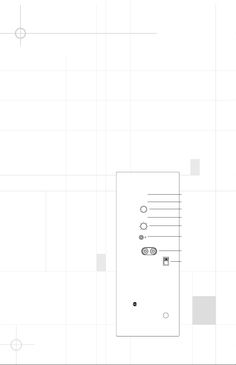
Subwoofer Controls PS1400
¡¡
On/Auto Switch – When
left in the “Auto” position, the
PS1400 subwoofer will
automatically turn on or go into
standby mode, depending on
whether it detects an audio
signal. When no signal is being
sent, the PS1400 will remain in
standby mode. When it senses
an audio signal, it will
automatically turn itself on and
begin playing. If the PS1400
does not sense a signal for
about twenty minutes, it will
switch itself into standby
mode. When this switch is
left in the “On” position, the
PS1400 will remain on, whether
or not program material is
playing.
™™
LF Crossover Switch – This
switch is used to engage the
PS1400’s internal crossover
when it is stacked with the
PT800 tower module, and when
no external crossover is being
used. In the “Normal” position,
the internal crossover is
engaged, and provides an
electronic 130Hz crossover for
the subwoofer which precisely
matches the passive 130Hz
crossover point of the output
terminal to the PT800. The
crossover is precisiondesigned to create a smooth,
integrated floorstanding
speaker system when the
PS1400 and PT800 are stacked.
In the “Separated” position,
the PS1400 provides an
electronic
300Hz rolloff for the
subwoofer,
which should be
augmented by the low-pass
crossover in the external
audio/video receiver or
processor. In this mode, the
PT800, whether or not it is
stacked with the PS1400,
should be given only a highpassed amplifier signal. That
signal should be crossed over
at 80Hz.
££
LF Level Control – This
control allows you to adjust the
level of the subwoofer within a
range of +/– 5dB. Start with the
control positioned at 0dB,
which is flat (neutral bass
level). If bass response is
unsatisfactory, due to either
your room acoustics or as a
matter of taste, experiment
with this control until the
desired bass level is achieved.
This control only affects all
information being received by
the speaker-level input.
¢¢
Polarity (Phase) Switch –
Use the “Normal” position
whenever the PS1400 and PT800
are stacked and the internal
crossover is used. It should
also be used when an external
crossover is used and all
amplifier channels are in phase.
The “Reverse” position may be
used when the PS1400 and
PT800 are separated, and due
to wave cancellation, bass
response is improved in this
position. “Reverse” may also
be selected when different
amplifiers are used that
have different polarity
configurations.
PERFORMANCE
SERIES
CAUTION
RISK OF ELECTRIC SHOCK
DO NOT OPEN
“WARNING: TO REDUCE THE RISK OF FIRE OR ELECTRIC SHOCK,
DO NOT EXPOSE THIS APPLIANCE TO RAIN OR MOISTURE.”
“AVERTISSEMENT: POUR PRÉVENIR LES RISQUES D’INCENDIE OU
DE CHOC ELECTRIQUE, EVITER D’EXPOSER CET APPAREIL A LA
PLUIE OU A L’HUMIDITE.”
MANUAL
AUTO
ON/OFF
SEPARATED
NORMAL
-2 0
-5 5
LF CROSSOVER
REVERSE
NORMAL
MIN MAX
– +
POLARITY
ON
OFF
POWER
LFE LEVEL
SYSTEM INPUT
LFE /SUBWOOFER
INPUT
LF LEVEL
®
NRTL/C
CSA 22-2
UL 1492
PN 336609-001
¡
™
£
¢
∞
§
¶
•
dB
Page 5

5
∞∞
LFE Level Control – This
control only affects the signal
sent to the LFE input. Adjust
the LFE level by starting with
the level controls on both
PS1400 modules in the
Minimum position. With 5.1, 6.1
or 7.1 source material playing,
advance the LFE Level controls
on both PS1400s slowly until
the desired amount of effects
channel is present. The normal
position for this control is full
clockwise, with LFE adjustments being made via the level
adjustments on your processor.
We have provided this control
because the LFE output level of
AV receivers and processors
can vary from manufacturer to
manufacturer.
If you are using the third or
fourth configurations, where
the main speakers are configured as “Small” and all bass
information is being sent to the
LFE inputs of the PS1400s, the
LFE Level control will operate
on all low- frequency information, and not just for the .1
channel effects.
§§
LFE/Subwoofer Input – This
jack accepts either an LFE or
line-level output from the
receiver or processor.
¶¶
System Input – These
binding posts accept a fullrange, amplified (speakerlevel) output from the receiver
or amplifier. This input should
be used whenever the PS1400
and PT800 modules will be
stacked and the internal
crossover used to form an
integrated floorstanding
speaker system. This input
should be used in that
configuration even if the LFE
input will also be used.
••
Power – This is the main
power switch, which must be
turned on for the amplifier and
electronic internal crossover to
function. If you will be away
from home for an extended
period of time, or if the PS1400
will not be used, turn this
switch off to conserve
electricity.
TROUBLESHOOTING
If there is no sound:
• Check that receiver/amplifier is on and a sourc e is playing.
• Check that the PS1400 is plugged in and its Power switch (8) is switched on.
• Check all wires and connections between receiver/amplifier and PS1400. Make sure all wires are
connect ed. Make sur e none of the speaker wires are frayed, cut or punctured.
• Review proper operation of your receiver/amplifier.
If there is low (or no) bass output:
• Make sure the connections to the left and right “Speaker Inputs” have the correct polarity (+ and –).
• Make sure the PS1400 is plugged into an active electric al outlet.
• Make sure the Power switch (8) is on.
• In Dolby Digital or DTS modes, make sure your receiver/processor is configured so that the subwoofer
and LFE output are enabled.
• Adjust the Polarity switch (4) if the PS1400 and PT800 are not stacked, or if they are stacked but
an external crossover is being used.
• Adjust the LF Level control (3).
• If the LFE input is in us e, adjust the LFE Level control (5).
Page 6

JBL PS1400 MECHANICAL/PACKAGING PARTS LIST
6
Description Part Number Qty
PS1400 CABINET (Black, Beech, Cherry) Not For Sale 1
AMPLIFIER ASSEMBLY Not For Sale 1
FRONT GRILLE 336605-001 1
14” WOOFER LE14-H, DCR = 6.0 Ω ±10% 336321-001 1
WOOFER GASKET 335651-001 1
PORT TUBE 335652-001 2
GRILLE CUP 333249-001 4
TRIM RING 335696-001 1
TRIM RING GASKET 336594-001 1
COVER PLATE 336597-001 1
COVER PLATE GASKET 336598-001 1
LOGO 335470-002 1
LOGO PLATE 336599-001 1
CROSSOVER NETWORK 336603-001 1
LED ASSEMBLY 335650-001 1
ALLEN WRENCH 336602-001 1
MOUNTING PILLAR 336596-001 2
SHORTING STRAP 336617-001 2
FOOT 301612-001 4
OUTER CARTON 336606-001 1
END PAD, TOP/BOTTOM 336607-001 2
OWNER’S MANUAL 336608-001 1
SAFETY SHEET 337344-001 1
FOOT INSTRUCTION SHEET 337546-001 1
SURVEY CARD 331384-001 1
WARRANTY CARD 331993-001 1
Page 7

7
Page 8

PS1400 BLOCK DIAGRAM
8
Page 9

9
Page 10

10
Page 11

11
Page 12

PS1400 ELECTRICAL PARTS LIST
PART #
Q'TY
DESCRIPTION
REFERENCE DESIGNATOR
12
Main Amp. board
052-000400-000 1 Bridge Rectifier P/N RS804 8A/400V BR1
032-100493-300 2 END Plastic Capacitor 1uF/63V J P:5 C104,119
034-330615-300 2 Electyl Capacitor TAPING 330uF/16V M (R)0812 P:5 C11,100
033-680464-270 2 NPE Capacitor 6u8/100V K10 (R)1020 GNE C113,136
033-470444-270 2 NPE Capacitor 4u7/50V K10 (R)8x13 SBE C114,137
031-100244-100 5 SMD Ceramic Capacitor 0u01/50V K 0805 X7R C12,13,27,28,54B
034-470763-301 4 Electyl Capacitor 4700uF/63V M (R) 25*40 C1-4
034-220525-300 6 Electyl Capacitor TAPING 22uF/25V M (R) 5x11 P:2.5 C14,15,25,26,34,36
034-100695-300 1 Electyl Capacitor 100uF/63V M (R)1012 P:5 C142
031-100343-100 2 SMD Capacitor 100pF/50V J 0805 NPO C20,63
031-220344-100 4 SMD Capacitor 220pF/50V J 0805 NPO C21,22,23,61
038-220393-300 2 MPE Capacitor 0u22/63V J C24,66
032-680353-300 2 END Plastic Capacitor 0u68/63V J P:5 C29,67
032-100484-200 1 END Plastic Capacitor 1uF/250V K P:15mm C30
038-330263-300 2 MPE Capacitor 0u033/100V J C31,68
032-390344-100 2 END Plastic Capacitor 0u39/63V J P:5 C32,33
031-330444-300 1 SMD Capacitor 3300pF/50V K 0805 X7R C35
031-100364-100 2 SMD Capacitor 0.1uF/100V K 1206 X7R C5,6
034-470515-300 1 Electyl Capacitor TAPING 47uF/16V M (R)0511 P:2.0 C54
034-100515-300 1 Electyl Capacitor TAPING 10uF/16V M (R)0511 P:2 C60
034-100625-301 1 Electyl Capacitor TAPING 100uF/25V M (R) P:2.5 ?? C62
034-220625-300 1 Electyl Capacitor 220uF/25V M (R)0812 P:5 C65
031-100344-100 14 SMD Capacitor 0u1/50V K 0805 X7R C69,112,115,135,138,10,48,50,51,70-74
034-470415-300 1 Electyl Capacitor TAPING 4u7/50V M (R)0511 P:2.0 C7
034-330525-301 1 Electyl Capacitor TAPING 33uF/25V M (R)0511 P:2.5 C8
072-040169-000 1 CONNECTOR 2 PIN JS-1001-2 P:2.5mm CONN3
072-010088-000 1 RCA JACK PN:DTR-0390B-E-G CONN7
039-100280-100 1 UL Capacitor 10NP/250V P/N:XG275M103VS04 CXAC1
054-000100-100 6 SMD DIODE ES1D 200V,1A,35ns D1,37,40,44,47,23
054-414802-100 28 SMD DIODE LS4148 D4,13-16,18,19-22,24-29,31,33,
34,38,41,45,48,50,51,54,55,56
054-001501-100 2 SMD ZENER DIODE 15V SOT-23 BZX84C15 D2,3
054-050601-100 1 SMD ZENER DIODE 5.6V SOT-23 BZX84C5V6 D30
054-001002-100 1 SMD ZENER DIODE 10V SOT-23 BZX84C10 D32
054-010300-100 2 SMD DIODE BAV103 SOD80C D5,6
073-050001-000 2 FUSE CLIP P/N:CFFH1206 For F1
091-000128-000 1 FUSE T4A/250V f5x20m/m F1
057-000027-000 1 THERMAL BREAKER P/N:802L-070 F2
044-100100-000 2 SMD FERRITE BEAD P/N:321611 100mHz 600R 1206 FB1,FB2
041-115000-000 1 BEAD COIL 115 OHM P/N:2773002112 J1
Page 13

043-820300-000 1 INDUCTOR 820uH YT-10034 L1
13
043-700100-000 1 INDUCTOR 70uHx2 YT-10024 L8
043-300101-000 2 INDUCTOR 30uH YT-10033 L9,10
054-540100-100 1 SMD PNP Transistor MMBT5401 LT1 Q1
051-640000-100 4 MOSFET N-Channel IRF640 TO-220 Q11,13,15,17
051-290700-100 4 Transistor P2N2907A TO-92 Q12,14,16,18
054-555100-100 1 SMD NPN Transistor MMBT5551 LT1 Q2
054-033906-100 4 SMD TR (MOTOROLA) MMBT3906LT1 SOT23 Q26,27,30,34
051-540101-000 1 Transistor PNP 2N5401 TO-92 Q3
054-211400-100 1 SMD NPN Transistor DTC114EK SMT3 Q5
051-000600-100 1 NPN Transistor MPSW06RLRA TO-92 Q6
054-033904-100 7 SMD TR (MOTOROLA) MMBT3904LT1 SOT23 Q7,9,24,25,28,29,32
051-005600-100 1 NPN Transistor MPSW56RLRA MPQ TO-92 Q8
024-820398-120 4 SMD Resistor 820R 1/8W J 0805 R1,10,11,12
024-100498-120 2 SMD Resistor 1K 1/8W J 0805 R110,169
024-100598-120 28 SMD Resistor 10K 1/8W J 0805 R5,16,18,20,23,39,46,4852,56,57,58,64,65,69
,100,102,105,118,121,122,125,126,128,
138,139,168,170
024-280498-100 1 SMDResistor 2K8 1/8W F 0805 R119
024-220598-120 1 SMD Resistor 22K 1/8W J 0805 R127
024-470398-120 4 SMD Resistor 470R 1/8W J 0805 R145,177,186,155
024-100698-120 5 SMD Resistor 100K 1/8W J 0805 R15,120,21,22,67
024-220498-121 2 SMD Resistor 2K2 1/8W J 0805 R17,306
022-300210-021 1 Cement Resistor 30R 10WS J SQM 35x16 R172
021-100401-020 2 Metal Oxide Resistor 1K 1W J FK TYPE R173,174
024-470698-120 2 SMD Resistor 470K 1/8W J 0805 R19,72
022-100005-020 1 Cement Resistor 0R1 5W J P/N:SQM 25x13 R2
024-470298-120 4 SMD Resistor 47R 1/8W J 0805 R24-27
024-330498-120 5 SMD Resistor 3K3 1/8W J 0805 R28,33,63,77,79
021-604498-100 1 Metal Film Resistor 6K04 1/8W F R29
024-470598-120 2 SMD Resistor 47K 1/8W J 0805 R3,171
021-105598-100 1 Metal Film Resistor 10K5 1/8W F R30
024-220298-120 2 SMD Resistor 22R 1/8W J 0805 R301,302
024-680498-120 1 SMD Resistor 6.8K 1/8W J 0805 R304
024-560498-120 1 SMD Resistor 5K6 1/8W J 0805 R305
021-332498-100 1 Metal Film Resistor 3.32K 1/8W F R31
021-750498-100 2 Metal Film Resistor 7K5 1/8W F R32,42
024-150598-120 1 SMD Resistor 15K 1/8W J 0805 R34
024-510398-120 1 SMD Resistor 510R 1/8W J 0805 R35
021-301498-100 2 Metal Film Resistor 3K01 1/8W F R36,43
024-680598-120 1 SMD Resistor 68K 1/8W J 0805 R37
021-357598-100 1 Metal Film Resistor 35K7 1/8W F R38
024-453598-100 1 SMD Resistor 45K3 1/8W F 0805 R40
024-820498-120 1 SMD Resistor 8K2 1/8W J 0805 R41
026-500595-254 1 VR 50KA LFE LEVEL CONTROL R45
024-200598-120 1 SMD Resistor 20K 1/8W J 0805 R47
024-330598-120 7 SMD Resistor 33K 1/8W J 0805 R49,60,70,4,6,13,14
Page 14

024-137698-100 1 SMD Resistor 137K 1/8W F 0805 R50
14
024-100398-120 1 SMD Resistor 100R 1/8W J 0805 R51
024-150498-120 2 SMD Resistor 1K5 1/8W J 0805 R53,73
026-200595-265 1 VR 20KB LEVEL CONTROL R54
024-300398-120 1 SMDResistor 300R 1/8W J 0805 R55
024-470498-120 2 SMD Resistor 4K7 1/8W J 0805 R58,59
024-470798-120 1 SMD Resistor 4.7M 1/8W J 0805 R61
024-300598-120 2 SMDResistor 30K 1/8W J 0805 R62,66
024-220798-120 1 SMD Resistor 2M2 1/8W J 0805 R71
021-820303-020 2 Metal Oxide Resistor 820R 3WS J 8x20 R76,78
024-000098-120 7 SMD Resistor 0R 1/8W J 0805 R8,321,303,307,309,311,316
024-750798-120 1 SMD Resistor 7M5 1/8W J 0805 R88
074-300018-000 1 RELAY P/N:943-1C-48D RLY1
074-001006-000 3 SLIDE SW P/N SHC-22P-09 SW1-3
072-040064-000 2 Terminal (PCB TYPE) PC250(t=0.8),T250MA TER6,TER4
025-010300-000 1 THERMAL SENSOR TSE-103 K L:50mm TH1
054-007200-100 5 SMD IC TL072CDR SO-8 (TI) DUAL OP-AMP U1-5
053-257400-100 1 IC;DIP 8P LM2574 HVN-15V 0.5A Step-Down Voltage
Regulator
U6
PREAMP PCB ASS'Y
031-100244-100 4 SMDCeramic Capacitor 0u01/50V K 0805 X7R C108,118,131,140
034-100715-202 2 Electyl Capacitor 1000uF/16V M (R) 10x17 P:5 C109,132
034-100625-303 1 Electyl Capacitor 100uF/25V M (R) P:2.5 C117
031-100344-100 8 SMDCapacitor 0u1/50V K 0805 X7R C75-78,80,82,83,85
031-560343-102 1 SMDCapacitor 560pF/50V J 0805 NPO C79
031-100343-100 2 SMDCapacitor 100pF/50V J 0805 NPO C81,84
031-560263-101 4 SMDCapacitor 56pF/100V J 0805 NPO C92,102,105,125
031-470244-102 4 SMDCapacitor 0u047/50V K 0805 X7R C93,94,101,124
054-000100-100 2 SMD DIODE ES1D 200V,1A,35ns D35,43
054-414802-100 3 SMD DIODE LS4148 D36,39,46
054-001002-100 2 SMD ZENER DIODE 10V SOT-23 BZX84C10 D42,49
072-040230-000 1 HEADER Right Angle 11PIN P/N:211-111-000-400 Pin1
072-040229-000 1 HEADER Right Angle 7PIN P/N:211-107-000-400 Pin2
051-222200-100 2 NPN Transistor MPS2222ARLRA TO-92 Q20,22
051-555100-000 2 Transistor NPN 2N5551 TO-92 Q21,23
051-000600-100 1 NPN Transistor MPSW06RLRA TO-92 Q31
054-540100-100 2 SMD PNP Transistor MMBT5401 LT1 Q33,40
024-390498-120 2 SMDResistor 3K9 1/8W J 0805 R130,161
024-220498-121 1 SMDResistor 2K2 1/8W J 0805 R134
024-680498-120 2 SMDResistor 6.8K 1/8W J 0805 R135,166
024-220398-120 2 SMDResistor 220R 1/8W J 0805 R136,167
024-270498-120 1 SMDResistor 2K7 1/8W J 0805 R157
024-000098-120 4 SMDResistor 0R 1/8W J 0805 R313,314,318,320
024-110598-120 2 SMDResistor 11K 1/8W J 0805 R74,99
Page 15

024-100598-120 12 SMDResistor 10K 1/8W J 0805 R75,82,83,92,98,132,133,148,163,164,181,15
15
6
024-470498-120 6 SMDResistor 4K7 1/8W J 0805 R80,84,151-153,183
024-100498-120 11 SMDResistor 1K 1/8W J 0805 R81,85,96,97,99,131,137,142,147,162,179
024-390598-120 2 SMDResistor 39K 1/8W J 0805 R86,94
024-220798-120 2 SMDResistor 2M2 1/8W J 0805 R87,93
024-100298-120 4 SMDResistor 10R 1/8W J 0805 R89,90,140,150
024-470398-120 1 SMDResistor 470R 1/8W J 0805 R91
024-200598-120 2 SMDResistor 20K 1/8W J 0805 R95,141
053-211100-000 2 IC;DIP IR2111 HALF-BRIDGE DRIVER U7,8
054-007200-100 2 SMD IC TL072CDR SO-8 (TI) DUAL OP-AMP U9,10
054-050601-100 2 SMD ZENER DIODE 5.6V SOT-23 BZX84C5V6 Z7,8
Page 16

16
Page 17

17
Page 18

18
 Loading...