


MS-8
8 Channel
System integration digital processor
SERVICE MANUAL
Released 2010
Discontinued XXXX
JBL Consumer Products
8500 Balboa Blvd.
Northridge, CA. 91329 Rev0 5/2010

1
MS-8
- CONTENTS -
SPECIFICATIONS ………………………………………..1
PACKAGING……………..…………………………..…....2
NOTICE REGARDING TESTING THE UNIT…….….…3
CONNECTIONS ……………………………..……………4
RESETTING THE MICROPROCESSOR………..…….15
REMOTE CONTROL …………….….…………..………16
TROUBLESHOOTING……………..…..…………………17
EXPLODED VIEW/PARTS LIST……...….….………….22
AMPLIFIER BLOCK DIAGRAM…….……………..….…23
ELECTRICAL PARTS LIST ..….…….……….…………26
P.C. B. DR A WINGS….……………………………….……30
IC/T R ANSI S TOR P I N O UTS..…………….……….….…..37
SCHEMATICS……………...……………….………..…...93
MS-8 Specifications
Power Output: 20W x 8 channels @ 4 ohms
Maximum Output Power: 30W x 8 channels @ 2 ohms
Frequency Response: 20Hz–20kHz
Signal-to-Noise Ratio (Line Input to Line Output): >90dB
Signal-to-Noise Ratio (Line Input to Spkr Output): >85dB
Maximum Input Voltage (Speaker-Level Input): 15V
Maximum Input Voltage (Line Input): 2.8V
Maximum Output Voltage (Line Output): 2.8V
Maximum Current Draw: 16A
Standby Current Draw: <0.01A
Display LCD Screen: 128 x 64 pixels
Power Requirement: 12V DC, negative ground
Main Unit Dimensions (L x W x H): 11-1/2" x 7-3/8" x 2-1/8" (293mm x 187mm x 55mm)
Display Unit Dimensions (H x W x D, w/ stand): 3-1/8" x 3-3/8" x 2-7/16" (79mm x 86mm x 62mm)
Weight: Main unit – 6.4 lb (2.9kg)
Display unit – 2.8 oz (80g)
Remote control – 1.4 oz (40g)
Fuse 25A
JBL continually strives to update and improve existing products, as well as create new ones. The specifications and details in
this and related JBL publications are therefore subject to change without notice.

2
MS-8
MS-8 PACKAGING
LITHIUM COIN BATTERY 3VDC CR2032

3
MS-8
NOTE: Although some typical connections and
®
controls are shown, the JBL
MS-8 digital
processor includes many features and digital
controls not found on conventional car audio
amplifiers. Also, the calibration, setup and
usage for the MS-8 is unique.
Details can be found in the MS-8 owner’s
manual, which can be downloaded here:
http://www.jbl.com/EN-US/Products/Pages/ProductDetails.aspx?PID=MS-8&accT=1&tsT=0&ovT=0
(click on link) then on Grey tab SUPPORT
4
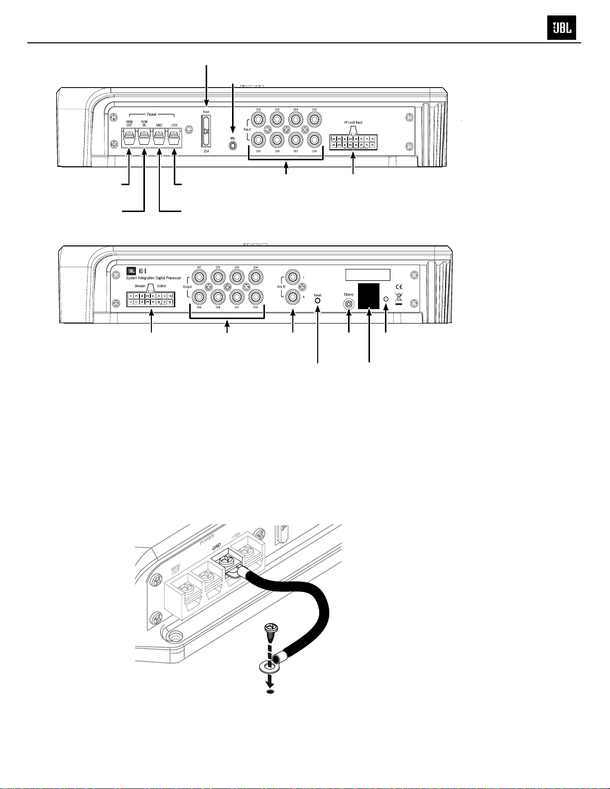
CONNeCTiONs
MS-8
CONNECTIONS
25A
fuse
Mic
connection
Englis h
connection
Remote in
connection
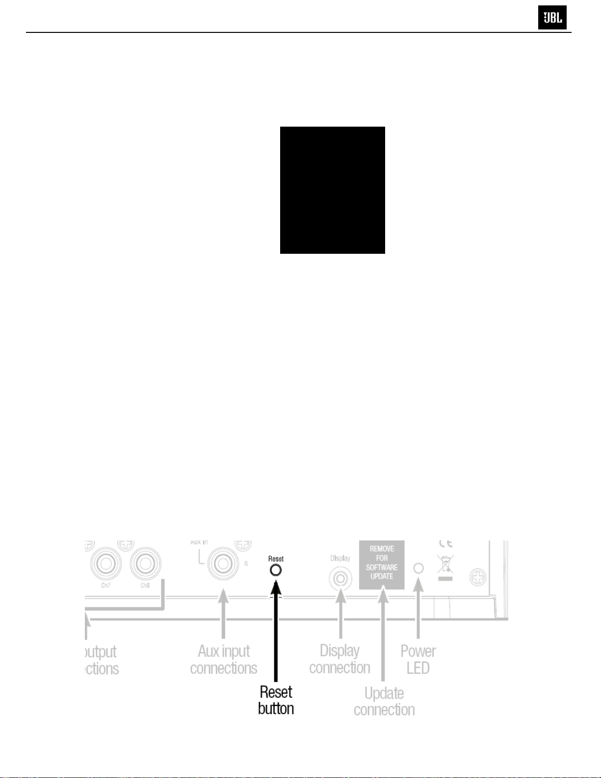
Speaker output
connections
+12V
connection
GND
connection
Line output
connections
Line input
connections
Aux input
connections
Reset
button
POWER
IMPORTANT: Perform the power connections in the following order.
1. Gnd: Connect this terminal to a paint-free location on the vehicle chassis.
Hi Level inputRemote out
Display
connection
connection
REMOVE
FOR
SOFTWARE
UPDATE
Update
Power
LED
IMPORTANT: Use at least 12-gauge wire for this connection.
Chassis
ground
(unpainted)
5
www.jbl.com
5
CONNeCTiONs
MS-8
CONNECTIONS
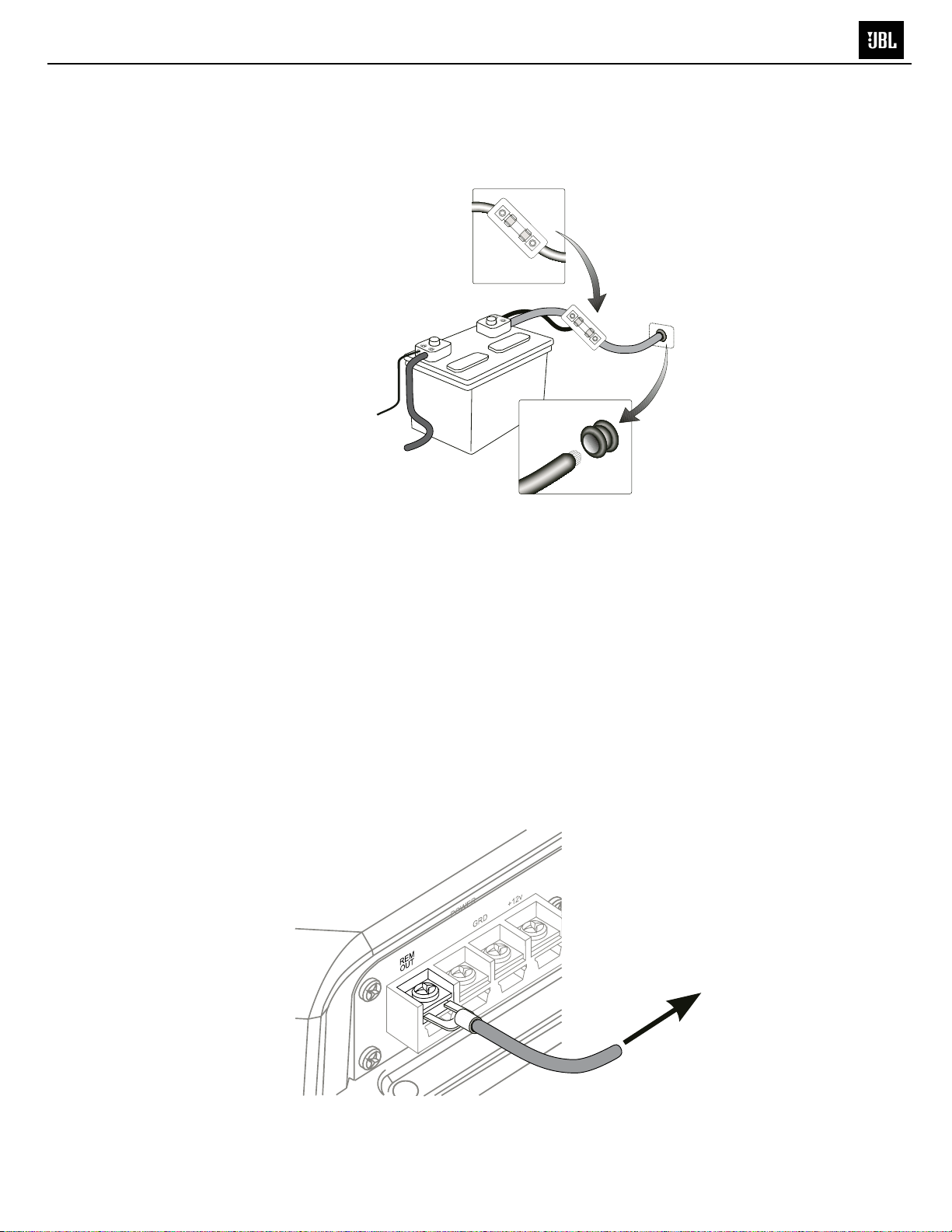
2. +12V: Connect this terminal to the vehicle battery’s positive (+) terminal. Insert a 25A fuse in series on
the +12V wire no further than 18 inches (46cm) from the battery terminal.
IMPORTANT: Use at least 12-gauge wire for this connection.
25A fuse within
18" of battery
terminal
1 x 25A
+
-
3. Rem Out: Connect this terminal to the remote turn-on terminals of all ampliers in the system. The
output is +12V DC, 1A.
IMPORTANT:TheMS-8MUSTcontroltheturn-onsignalofalltheotherampliers
that follow the MS-8 in the signal path.
Ifyoursystemincludesafactory-installedoutboardamplier,theturn-onsignal
maybeavailableattheamplier.Ifyourfactoryamplierhasaturn-onwire,cutit
and connect the head-unit side of the wire to the MS-8’s Rem In terminal and the
ampliersideofthewiretotheMS-8’sRemOutterminal.
This arrangement will allow the factory stereo to turn the MS-8 on whenever the
stereoisturnedonandwillallowtheMS-8toturnthefactoryamplieronandoff.
It will also help to eliminate audible clicks and pops when the system turns on and
off.
Cable from MS-8
+12V terminal
Use a grommet
through the
firewall
To turn-on
terminals of
all system
amplifiers
6
6
eCTiONs
MS-8
CONNECTIONS
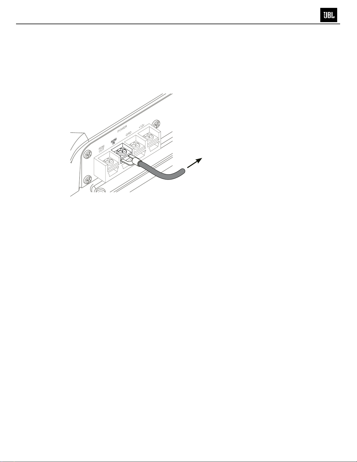
Rem In: Connect this terminal to the remote turn-on output of the system’s source unit, if the
source unit has a remote turn-on output. Alternately, you can connect this terminal to the vehicle’s
accessory (ACC) power circuit. Any voltage over +4V DC at this terminal will trigger the MS-8 to
turn on.
NOTE: See Step 3 for more details about connecting the Rem In terminal to a factory-installed
stereo system.
To head unit
remote turn-on
or vehicle
ACC terminal
Englis h
AUDIO INPUTS
Many factory-installed systems include on-board equalization and crossovers that make simple
connection of aftermarket products difcult. The MS-8 includes the signal-summing circuitry, signalconditioning EQ and time-correction processing that are necessary to reconstruct a at, full-range,
two-channel signal when you use the MS-8 with factory-installed equipment.
Aftermarket head units with line outputs provide a at, full-range, two-channel signal on their front line
outputs, so you need to connect only those channels to the MS-8.
7
7
MS-8
CONNeCTiONs
CONNECTIONS
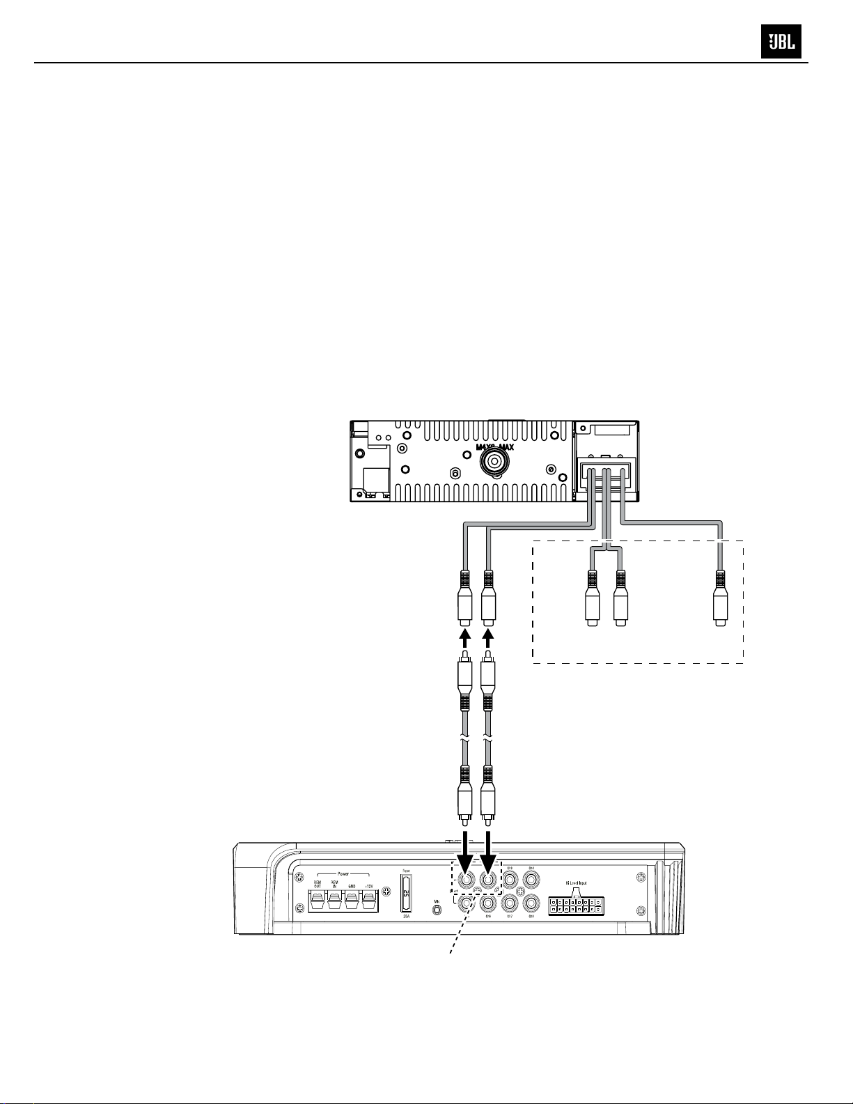
Connecting an aftermarket head unit
If you’re using the MS-8 with an aftermarket head unit that has RCA-type outputs, connect the head unit’s
front left and front right outputs to the MS-8’s line inputs 1 and 2 only. Do NOT connect any other head-unit
the input signals and derive as many output signals as your speaker system requires.
IMPORTANT: Do not connect the head unit directly to any ampliers, including a subwoofer amplier. The
MS-8’s signal processing takes nearly 8ms, so any signals connected directly to a head-unit will be ahead
of the signals leaving the MS-8 by about 8ms. This difference will cause them to be out of sync with the
signals that pass through the MS-8. The MS-8 must generate all the signals that are sent to all of the
system’s speakers!
Aftermarket head unit
MS-8 main unit
Front
line out
RCA
audio cables
Line inputs
1 and 2
Rear
line out
DO NOT USE
Subwoofer
line out
8
8
ONNeCTiONs
MS-8
CONNECTIONS
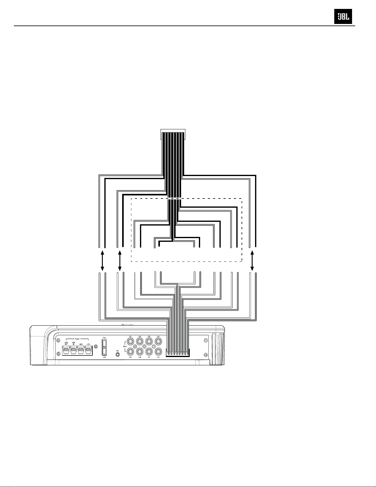
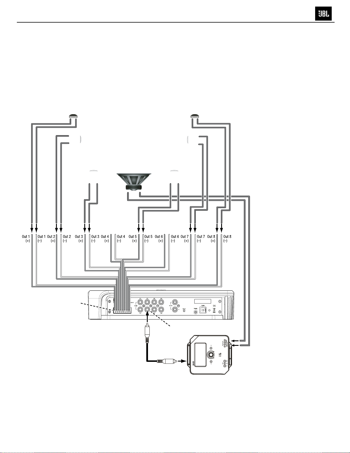
Connecting a factory radio/head unit
If you will be connecting the MS-8 to a factory-installed stereo or a factory-installed amplier (often located in
the vehicle’s trunk), connect each of your factory front-speaker and subwoofer outputs to one of the MS-8’s Hi
Level inputs. Be sure to connect the outputs for all speakers that are part of the vehicle’s front left and front right
speakers.
You can connect the factory front speaker outputs to any MS-8 Hi Level inputs, but factory stereo or amplier
subwoofer outputs MUST be connected ONLY to the MS-8’s channel 7 and/or 8 inputs. During the calibration/
setup process, the MS-8 will “normalize” the input signals and derive as many output signals as your speaker
system requires.
Factory stereo
wiring harness
Englis h
MS-8 main unit
Front left
+ –
Connect
+ –
+ –
+ –
Ch 1
Front right
Ch 2
Side left
Ch 3
Side right
Rear right
DO NOT USE
Ch 4
Ch 5
Subwoofer*
Center
Rear left
+ –
Connect
+ –
Ch 6
Ch 7
Ch 8
*NOTE: Subwoofers
MUST be connected
to MS-8 input 7
and/or input 8
NOTE: The above illustration shows only a general connection example and does not represent any particular
vehicle audio system.
Insert the included Hi Level input wiring harness into the MS-8’s Hi-Level-input connector until it locks into place.
IMPORTANT: The MS-8’s Hi Level input wiring harness has gray and white wires. Each channel has a white
(positive or “+”) wire and a gray (negative or “–”) wire. Each wire is labeled with its channel number and polarity,
and is pre-stripped for easy connection to your factory radio’s speaker outputs. Make sure that the ( + ) and
( – ) wires do not touch each other. Touching wires can cause a short circuit that can damage the
MS-8 or your head unit.
To ensure proper polarity, connect each factory-radio positive (+) terminal to the respective
“+” terminal on the MS-8. Connect the negative (–) terminals in a similar way.
9
9
MS-8
CONNeCTiONs
CONNECTIONS
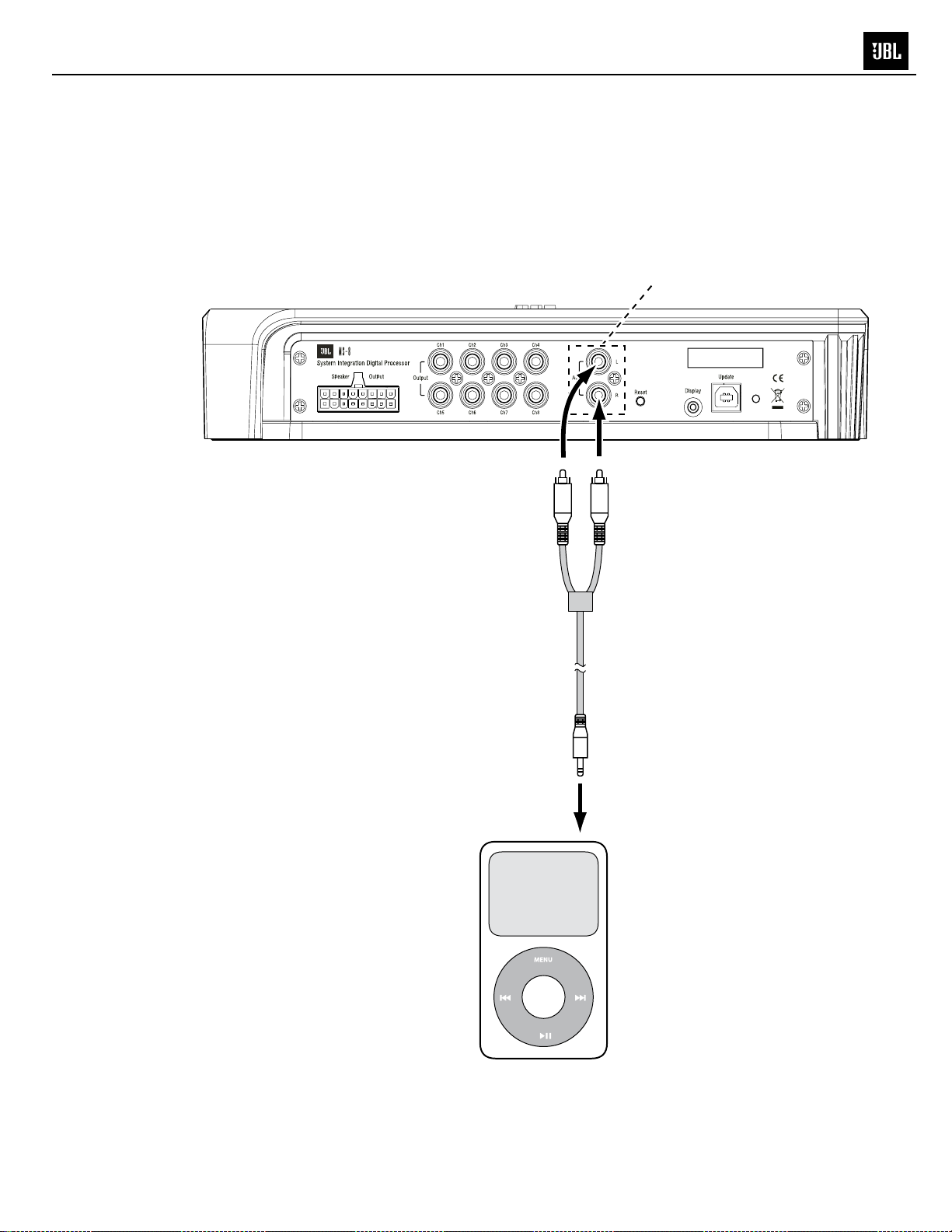
Aux input: If you will be using a portable music player or CD player as an auxiliary audio-source unit,
connect its line or headphone output to the MS-8's Aux input using a cable that terminates in stereo
RCA audio connections. You can switch between the MS-8's Head Unit inputs and Aux input in the
MS-8's Input Selection menu. See Main Menu, on page 35.
Aux
input
To
headphone
output
10
10
MS-8
CONNECTIONS
AUDIO OUTPUTS
Congurations
You can congure the MS-8’s eight outputs in a variety of ways, depending on the speakers that are
installed in your vehicle. You can congure the MS-8 for a system with one-way (full-range), two-way or
three-way front speakers, a one-way or two-way center speaker, side speakers, rear speakers and one
or two subwoofers. Remember, however, that the total number of available channels is eight, so any
combination of front, center, side, rear and subwoofer channels cannot total more than eight. For example,
if you are allocating six channels for a pair of tri-amped, three-way front speakers, there will be only two
remaining channels, which will not accommodate a pair of rear speakers and a subwoofer.
If your system will include more than eight channels, use additional separate ampliers (connected to the
MS-8’s line outputs) for the additional channels. For example, if you want to build a 7.1-channel system
that includes bi-amped or tri-amped front speakers, use the MS-8 to generate the 7.1-channel outputs
(seven full-range and one subwoofer). Connect the MS-8’s front line outputs to the inputs of an additional
crossover (or amplier containing an additional crossover) that will provide the separate channels required
to drive the front midbass, midrange and/or tweeters separately.
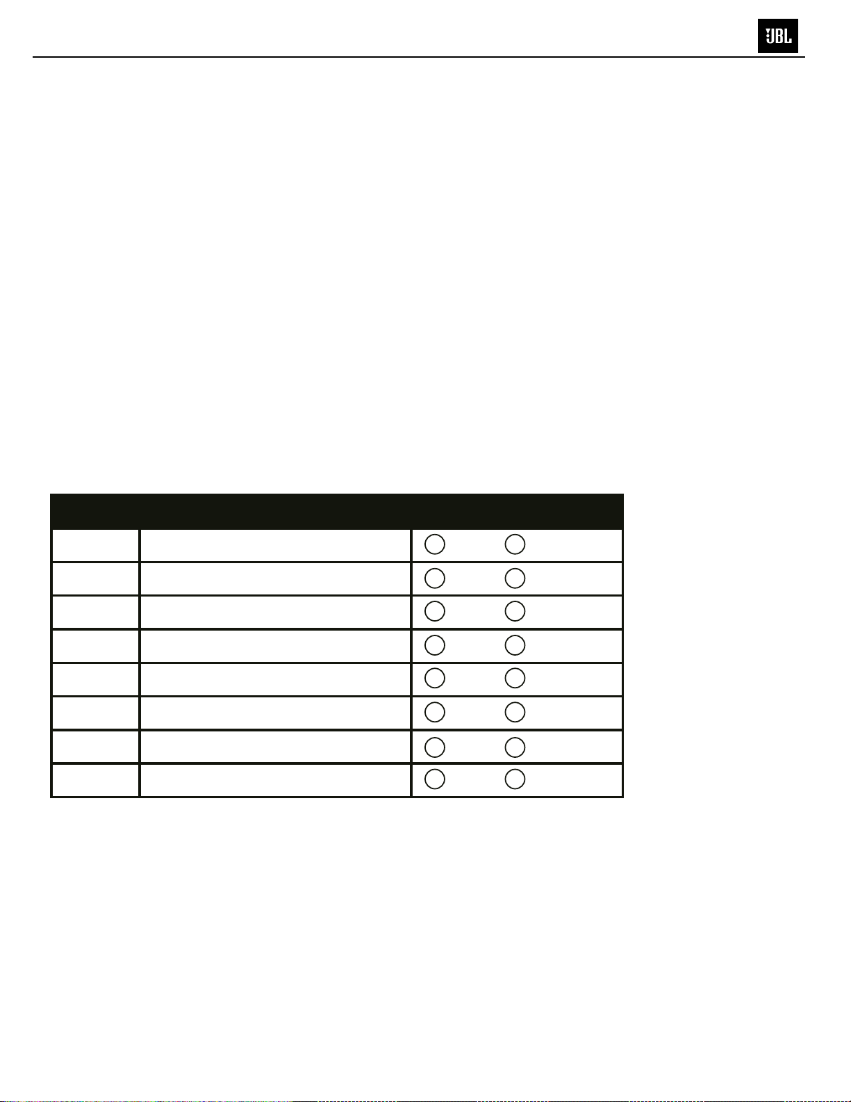
Use the Conguration Chart below to record which of your system’s speakers you have connected
to which of the MS-8’s outputs. Keeping this record will simplify channel assignment during the setup
procedure. See Main Menu, on page 35.
CTiONs
Englis h
Output # Channel / Speaker Connected Output Connector Used
1 RCA SPEAKER
2 RCA SPEAKER
3 RCA SPEAKER
4 RCA SPEAKER
5 RCA SPEAKER
6 RCA SPEAKER
7 RCA SPEAKER
8 RCA SPEAKER
11
11
CONNeCTiONs
MS-8
CONNECTIONS
Speaker Outputs
If you’ll use the MS-8’s built-in power ampliers to drive your system’s speakers, connect the speakers to the
MS-8’s speaker outputs. Insert the included speaker-output wiring harness into the MS-8’s speaker output
until it locks into place. See Main Menu, on page 35.
IMPORTANT: The MS-8’s speaker-output wiring harness’s wires have clear insulation. Each channel has a
copper (positive or “+”) conductor and a silver (negative or “–”) conductor. We have labeled each conductor
with its channel number and polarity, and pre-stripped it for easy connection to your system’s speakers.
Make sure that the ( + ) and ( – ) wires do not touch each other. Touching wires can cause a short
circuit that can damage the MS-8.
Left front
(tweeter)
+
– + –
+
Left front
(midrange)
–
Right front
(tweeter)
Right front
(midrange)
–
+
Vehicle
Speaker System
+
Left side
(coaxial)
–
Left rear
(coaxial)
+
–
Right side
(coaxial)
Right rear
(coaxial)
+
–
+
–
MS-8
main unit
Speaker-output
wiring harness
To ensure proper polarity, connect each MS-8 positive (+) terminal to the respective
“+” terminal on the speaker. Connect the negative (–) terminals in a similar way.
12
12
eCTiONs
MS-8
CONNECTIONS
NOTE: You can power some of the system's speakers by the MS-8's ampliers and some by outboard
ampliers, but you should use only one connection type per output. For example, output channel 1 may use the
MS-8's amplifer OR an outboard amplier, but not both. Be sure to use the chart above to note which speakers
are connected to which MS-8 channels.
Left front
(Tweeter)
+
– + –
+
–
Left front
(midrange)
Vehicle
Speaker
Right front
(midrange)
System
Left rear
(coaxial)
+
Subwoofer
–
+ –
Not
used
Right rear
+
Not
used
Right front
(Tweeter)
–
+
(coaxial)
–
Speaker output
wiring harness
Line output
#6
Subwoofer
amplifier
13
13
CONNeCTiONs
MS-8
CONNECTIONS
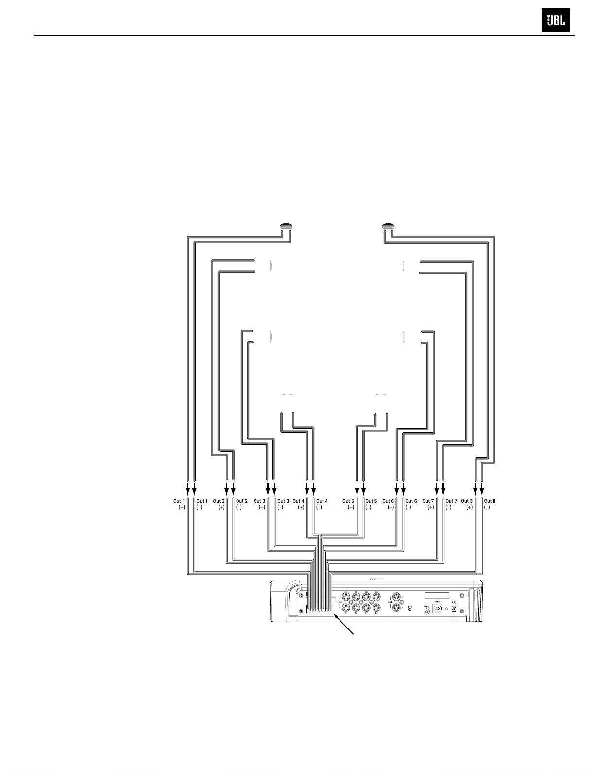
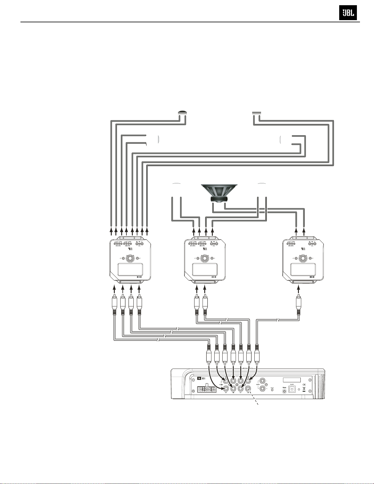
Line Outputs
If you’ll be using additional outboard power ampliers to drive your system’s speakers, connect their inputs to
the MS-8’s line-output connectors. You can power some of the system’s speakers by the MS-8’s ampliers
and some by outboard ampliers, but you should use only one connection type per output. For example,
Output Channel 1 may use the MS-8’s amplier OR an outboard amplier, but not both. Be sure to use the
chart above to note which speakers you have connected to which of the MS-8’s channels.
Front
speaker
amplifier
Left front
(tweeter)
+
+
Left front
(midrange)
–
Left rear
(coaxial)
+
–
Rear
speaker
amplifier
Vehicle
Speaker
System
Subwoofer
+ –
Right front
(tweeter)
Right front
(midrange)
Right rear
(coaxial)
+
–+–
–
+
–
Subwoofer
amplifier
RCA
audio cables
MS-8 main unit
14
Ch. 8 is unused
in this example
14
ONNeCTiON
C
MS-8
CONNECTIONS
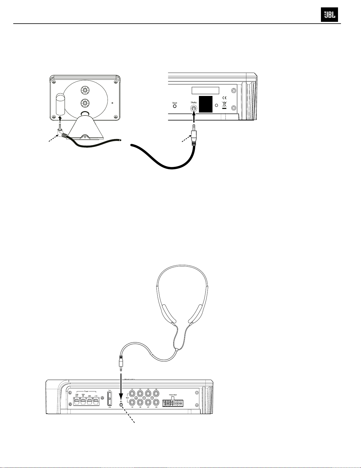
DISPLAY
Use the included 6m (19.7 ft) cable to connect the display unit to the MS-8’s main unit’s display connection.
Insert the cable’s straight connector into the main unit and the right-angle connector into the display.
s
REMOVE
FOR
SOFTWARE
UPDATE
Plug angled connector
into display
Plug straight connector
into main unit
NOTE: The display unit must be connected during setup but may be disconnected after setup and after
you’ve made any additional adjustments in the Audio Controls menu (see Audio Controls Menu, on page 36).
If the display unit is disconnected after setup and nal adjustment, you will not be able to make any additional
MS-8 adjustments, and the remote control will not function. See Main Menu, on page 35.
MICROPHONE
The included binaural microphone headset must be connected to the MS-8’s Mic connection during the
calibration/setup process. Once setup is complete, unplug the microphone headset and store it in a safe
place.
IMPORTANT: Do not use any other microphone with the MS-8.
Connect to mic input
15
15
CONNeCTiONs
MS-8
CONNECTIONS
UPDATE
Use the Update port only for rmware upgrades. We have covered it with a sticker that you should leave in
place until you are ready to install a rmware upgrade that you will download from www.JBL.com.
REMOVE
FOR
SOFTWARE
UPDATE
After downloading a rmware upgrade into your PC, remove the sticker and connect the
Update port to a USB port on your PC. Follow the directions that accompany the upgraded
rmware to upload the new rmware from your PC to the MS-8.
RESETTING THE MICROPROCESSOR
If the MS-8 stops responding to the remote control (even after you’ve replaced the
remote’s battery) or fails to operate in the way this manual describes, use a pen or
similar pointed object to press the Reset button on the main unit
NOTE: Pressing this Reset button will NOT erase the calibration settings.
To erase all settings and set the unit back to factory defaults, this should be done in
the system menu; see page 39 of the owner’s manual for details
16
16
UsiNG The reMOTe CONTr
MS-8
OL
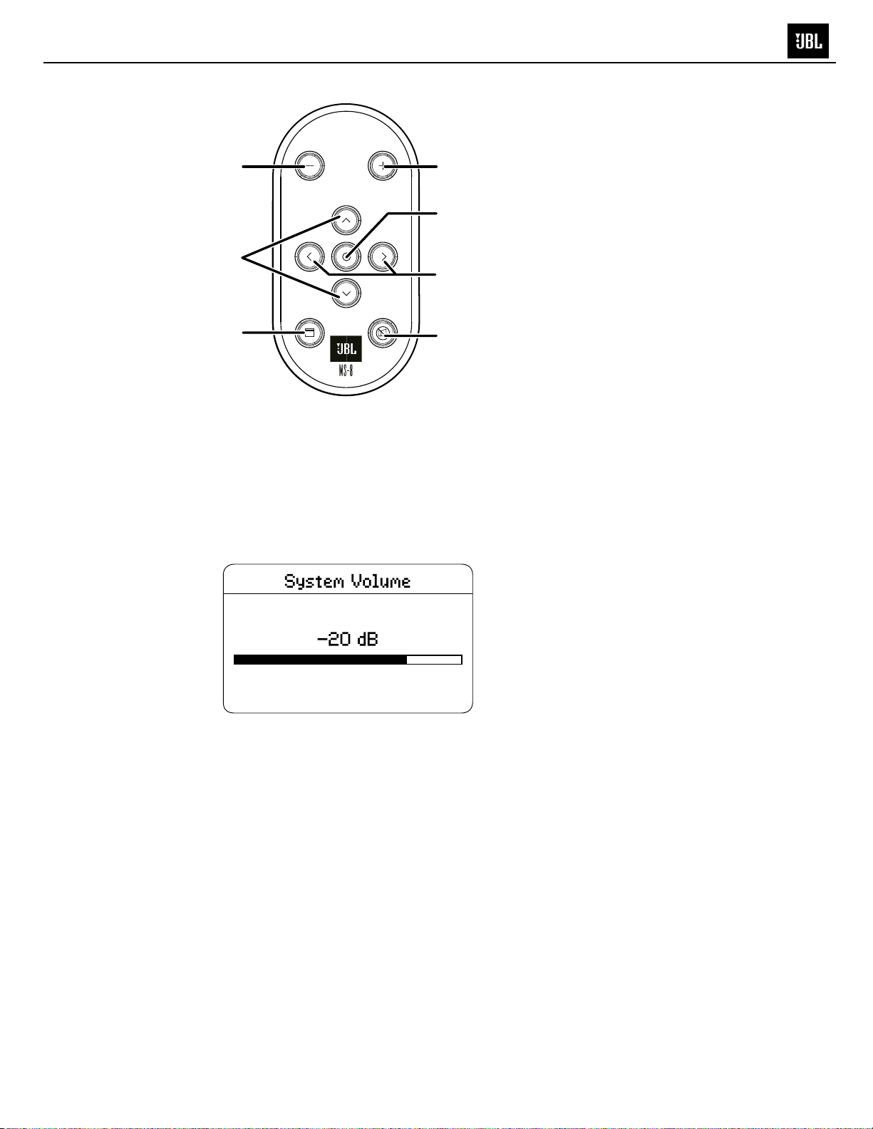
USING THE REMOTE CONTROL
Volume Down
button
Up/Down
navigation
buttons
Back
button
Volume Up
button
Select
button
Left/Right
navigation
buttons
Mute
button
Volume Up and Down buttons: Pressing either of these buttons at any time (except during the
setup/calibration process) will display the MS-8’s System Volume screen, allowing you to change
the audio volume. The volume range is between –80dB and 0dB.
Navigation and select buttons: Use the four navigation buttons (Up, Down, Left and Right) to navigate
through the MS-8’s various setup and operation screens. The Select button selects or otherwise
changes the state of a highlighted item.
Back/menu button: Momentarily pressing this button causes the display to revert to the next-higher
menu. Holding the button reverts to your default screen (either the Main Menu or Audio Controls screen)
from whatever screen is active at the time. See Default Screen, on page 40.
Mute button: Press to mute the sound; press again to restore the sound. (Pressing either the Volume
Up or Volume Down button also restores the sound.)
23
17
TrOUBLeshOOTiNG
MS-8
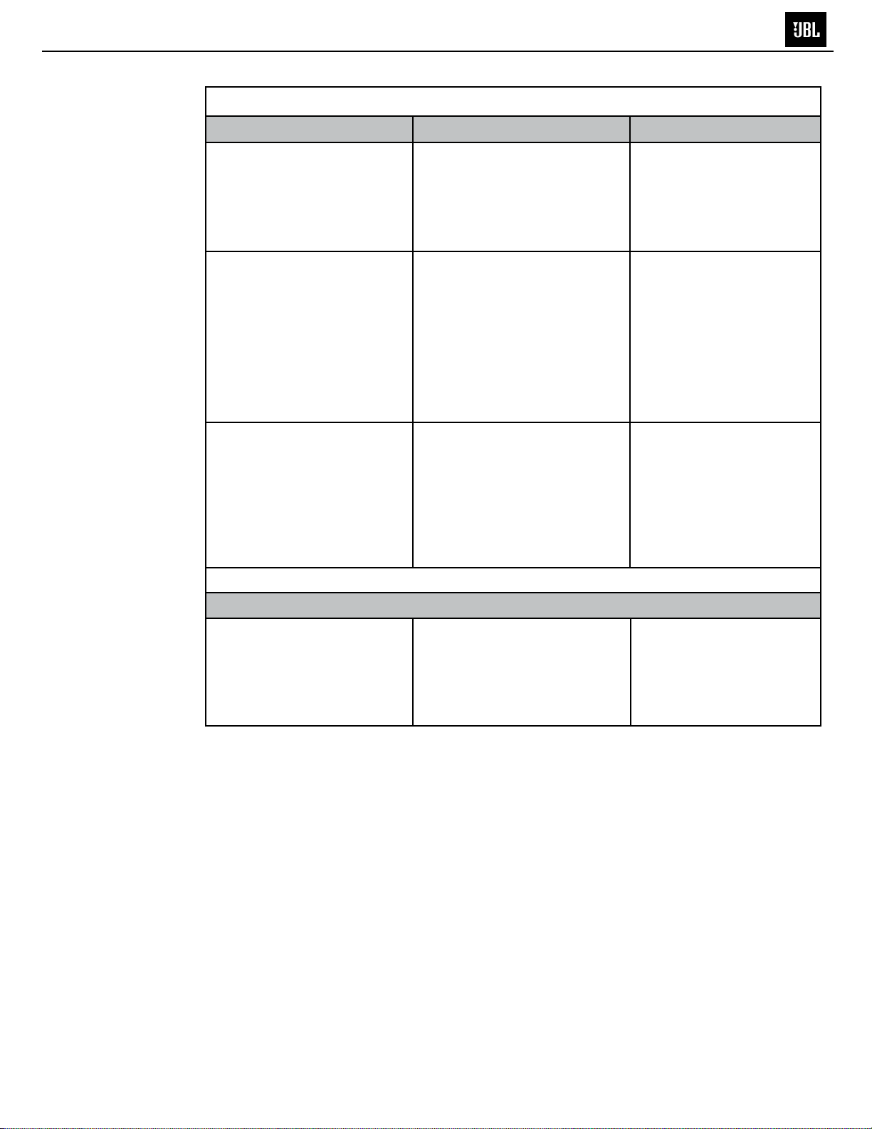
TROUBLESHOOTING
If your MS-8 doesn’t seem to be working the way it should, read this section to
see if the problem and possible solution are listed here. If, after you try all of the
solutions listed here, the problem persists, contact JBL Customer Service at
516.255.4JBL (4525).
NOTE PAGE NUMBER REFERENCES IN THIS SECTION REFER TO THE OWNER'S MANUAL
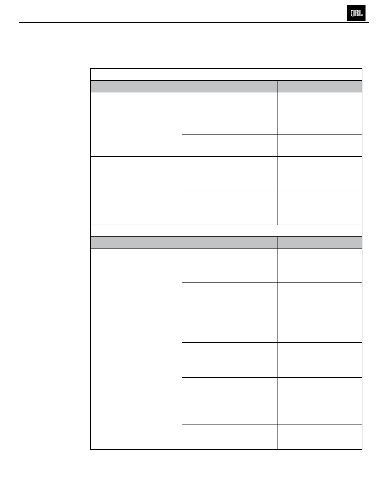
POWer
Symptom
The power LED does not
illuminate.
The power LED illuminates,
but the display does not
illuminate.
sOUNd
Symptom
There is no sound in all
channels.
Possible Cause
The +12V, Gnd or Rem In
terminals are not properly
connected.
The fuse is blown.
The display is not properly
connected.
The MS-8’s microprocessor
needs to be reset.
Possible Cause
Improper input connections.
Solution
Conrm that all power
connections are correctly
made according to this
manual. See Connections:
Power, on page 5.
Replace the fuse with an
identical 25A fuse.
Check the connections at
display and at main unit.
See Connections: Display,
on page 14.
Press Reset button with a
pen or similar object. See
Resetting the
Microprocessor, on page 41.
Solution
Conrm that all the required
channels of the source unit
are properly connected. See
Audio Inputs, on page 7.
Calibration/setup procedure
has not been performed.
Incorrect input is selected
on the MS-8
The MS-8’s System Volume
is turned all the way down.
The head-unit or source-unit
volume control is turned all the
way down.
Perform the calibration/
setup procedure. (The
procedure must be
performed before the MS-8
will pass an audio signal
through to its outputs.) See
Calibration/Setup, on page
24.
Select the correct input
using the MS-8’s Input
Selection menu. See Input
Selection Menu, on page 35.
Set the MS-8 System
Volume at –20dB. See
Acoustic Calibration, on
page 32, and Volume Up
and Volume Down Buttons,
on page 35.
Turn the head-unit or
source unit volume up to a
normal level.
42
18
TrOUBLeshOOTiNG
MS-8
TROUBLESHOOTING
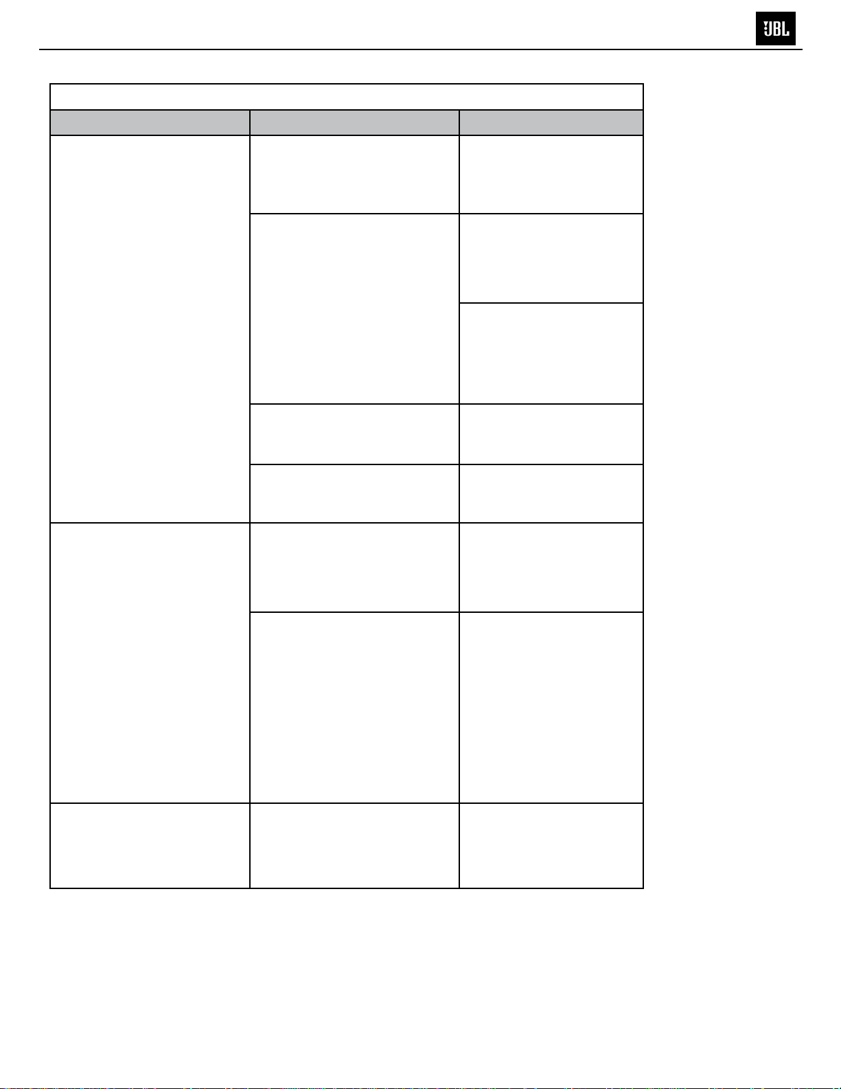
sOUNd
Symptom
There is no sound in one or
more channels.
Possible Cause Solution
Improper input connection.
Improper output connection.
Improper speaker connection to
outboard amplier.
Outboard amplier channel is
not functioning.
Conrm that all required
channels of the source unit
are properly connected. See
Audio Inputs, on page 7.
Conrm that the speaker
in question is properly
connected to the MS-8’s
speaker output. See Audio
Outputs, on page 10.
If the speaker is connected
to an outboard amplier,
conrm that the outboardamplier channel is properly
connected to the MS-8. See
Audio Outputs, on page 10.
Conrm that the speaker is
properly connected to the
outboard amplier.
Troubleshoot the outboard
amplier and replace it, if
necessary.
The sound comes from the
incorrect speaker.
Sound comes from only the
left or right side speakers; or
sound comes from only the
front or rear speakers.
Incorrect output connection.
Incorrect channel assignment.
The Balance and/or Fader
controls are set all one way
or another.
Conrm that the speaker is
connected to the correct
MS-8 speaker output or
to the correct outboard-
amplier channel.
Perform the Input
Setup (page 25) and
Output Setup (page 26)
procedures again. (See
the If you make a mistake
sidebar, on page 27.)
Before beginning the
procedures, make sure
to conrm and document
which speakers are
connected to which MS-8
Use the MS-8’s System
Levels screen to set the
controls to their center
positions. See Audio
Controls Menu, on page 35.
43
19
TrOUBLeshOOTiNG
MS-8
TROUBLESHOOTING
sOUNd
Symptom
The source connected to the
Aux input is too quiet or too
loud.
The sound in all speakers is
distorted.
Possible Cause Solution
The Aux input level is not
properly set.
The source player’s volume
control is set too low.
The MS-8’s System Volume
control and the head unit’s
volume control are not properly
adjusted.
Use the MS-8’s System
Levels screen to set the
Aux level so that the Aux
source’s level matches
the level of the head unit
source. See Audio Controls
Menu, on page 35.
Set the source player’s
volume control to a higher
level.
If you have connected the
front speakers to be driven
directly by the MS-8’s
internal amplier, set the
MS-8’s System Volume at
–20dB.
If you have connected
the front speakers to an
external, higher-powered
amplier that is connected
to the MS-8’s line outputs,
set the MS-8’s System
Volume to a level lower than
–20dB.
The MS-8’s Bass Control and/
or Graphic EQ bass bands
are set with too much boost,
combined with a high System
Volume setting.
In either case, you should
use the head unit’s volume
control to control the
system’s volume. You may
need to make a minor
adjustment to the MS-8’s
System Volume setting to
allow you to use more of
the range in the head unit's
volume control.
If you hear distortion when
the head unit’s volume
control is at higher settings,
increase the MS-8’s System
Volume to compensate.
This change will let you
keep the head unit’s volume
control within a lower (more
distortion-free) portion of its
range.
Reduce the Bass Control
and/or Graphic EQ boost
levels. We recommend
never combining high levels
of Graphic EQ bass-band
boost with high Bass
Control boost.
44

20
rOUBLeshOOTiNG
MS-8
TROUBLESHOOTING
sOUNd
Symptom
The center speaker seems
too loud when you’re listening
to news, sports or talk radio
stations.
The sound always has too
much or too little bass or
treble.
Music is dull, lifeless and
conned-sounding, with poor
stereo imaging.
Possible Cause Solution
The MS-8’s Logic 7 processing
is (by design) sending all mono
information to the center
speaker.
The MS-8’s Tone Controls
and/or Graphic EQ are misadjusted.
The MS-8’s Logic 7 and digital
signal processing (DSP) are
defeated.
Use the MS-8’s System
Levels screen to reduce the
center speaker’s level until
it sounds correct to you.
Then save the settings as
one of the MS-8’s Favorite
settings so you can recall it
whenever you listen to this
type of station. See Audio
Controls Menu, on page
36, and Favorites Menu, on
page 39.
Use the MS-8’s Tone
Controls and/or Graphic EQ
screens to return all controls
to their center positions. See
Audio Controls Menu, on
page 36.
Use the MS-8’s Audio
Controls menu to activate
Logic 7 and DSP. See , on
page 36.
The MS-8’s System Volume
was set at too high a level
during the acoustic-calibration
process.
Perform the acousticmeasurement portion
of the calibration/setup
process again, with the
MS-8’s System Volume set
at –20dB. See Acoustic
Calibration, on page 32.
45
21
TrOUBLeshOOTiNG
MS-8
TROUBLESHOOTING
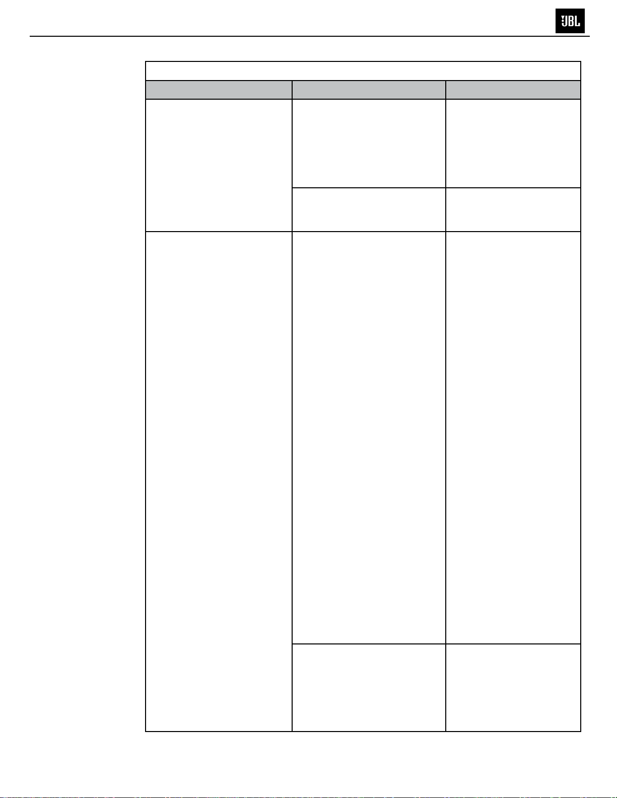
errOr MessAGes ON disPLAY
Symptom
“MS-8 Has Overheated…”
“No DSP Response…”
“Voltage Too High…” or
“Voltage Too Low…”
Possible Cause
There is insufcient cooling air
around the main unit.
There has been a possible
electrostatic discharge within
the main unit.
The vehicle’s electrical system
may be malfunctioning.
Solution
Re-install the main unit in a
less conned area that will
allow cooling air to circulate
around the unit. See
Choosing a Location for the
Main Unit, on page 17.
If the message displays only
once and the MS-8 resets
without incident, no further
involvement is necessary.
If the message displays
often, contact JBL
Technical Support at
516.255.4JBL (4525).
If the message displays only
once and the MS-8 resets
without incident, no further
involvement is necessary.
If the message displays
often, contact your vehicle’s
dealer or mechanic.
MisCeLLANeOUs
Symptom
The display is hard to read.
Possible Cause
The Brightness and/or Contrast
controls are not properly
adjusted.
Solution
Use the MS-8’s Brightness
and Contrast screens
to adjust the display for
better viewing. See System
Settings Menu, on page
40.
46
22
MS-8
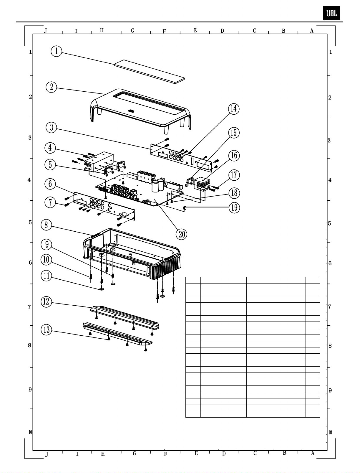
MS-8 EXPLODED VIEW
Item Part Number Description Qty
1 W-DB-800010015 Lens 1
2 W-SG-0002-0111 Top cover 1
3 W-MK-0009-0101 Input Board Plate 1
4 W-SR-MS80-0425 SUB Heatsink A 1
5 W-ZA-B00120100 IC Bracket A 2
6 W-MK-0010-0101 Output Board 1
7 W-LS1AM0300607 Screw PM3*6 8
8 W-XG-0005-0101 Bottom 1
9 W-LS1BM0040081 Screw BM4*8 3
10 W-LS1AY0401201 Screw PM4*12 4
11 W-JD-B40600515 Thermally conductive Pad 3
12 W-ZA-H00010101 Bracket 2
13 W-LS1KM0040071 Screw KM4*7 8
14 W-LS1AJ0301001 Screw PA3*10 9
15 W-ZA-B00130100 IC Bracket B 1
16 W-SR-MS80-0325 SUB Heatsink B 1
17 W-LS1BE0301607 Screw BM3*16 6
18 W-LS1AY0300601 Screw PM3*6 9
19 W-ZL-10002A-35 LED Spacer 1
20 Main PCB 1
NOT SHOWN W-1601-253G-01FuseDIP 25A/32V LittleFuse
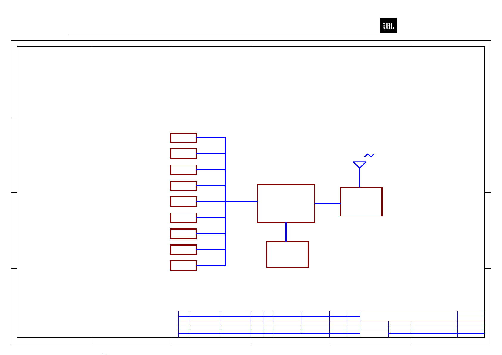
ROUT[3:0]
RIN[4:2]
Microcontroller
NOTE: Unless otherwise specifed all non-polarized capacitors are
23
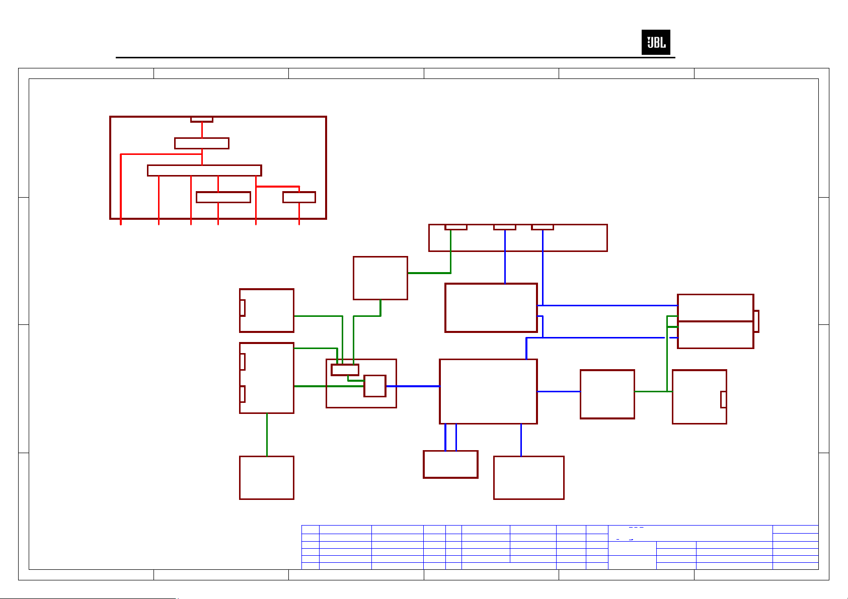
MS-8
From Car Battery
D
VCAR
3P3V
To Power
Amp
To DSP I/O,
SDRAM and
Flash
BATT
FUSE, FILTER
TDA3681J LINEAR REG
5V 8P5V
SWITCHING REG
1P2V
TO ADC,
To
DAC,
DSP
Audio
Core
I/O
Always On.
To Autosense,
and
C
From Binaural Microphone
Line-levelInputs
B
Speaker-levelInputs
REGULATORS
5V_ON
To Display(LCD, uC, RFReceiver)
MIC IN
Sheet 10
AUDIO IN
Sheets 12,13
L[4:1]+
R[4:1]+
L[4:1]R[4:1]-
SWITCH
Sheet 7
5V_DISP
LIN1
RIN1
LIN[4:2]
MicL_analog,MicR_analog
MUX
AK5358AET
AUX PRE-AMP
Sheet 11
ADC
ADCx4
Sheet 8
I2S_IN[3:0]
iAUDL,
iAUDR
JTAG
RS232
ToLaptopFrom Aux Src
MICROCONTROLLER
C8051F347
DSP
Sheets 2, 3
TMS320DA610B-GDP
ceramic, 0603 package, 50V (or higher), and 10% tolerance. Unless
otherwise specified, all resistors are 0603 package, 5% tolerance
To Display &RF Receiver
I/O CONNECTORS
USB
Sheet 6
I2S_OUT[3:0]
ED[31:0]
EA[21:2]
Sheet 17
I2C 1
I2C 2
DAC
Sheet 9
AK4359VF
LOUT[3:0]
AUDIO POWER AMP 1
AUDIO POWER AMP 2
AUDIO OUT
Sheets 15,16
Speaker-levelOutputs
Sheet 18
Sheet 18
TDA7563B
Line-levelOutputs
654321
D
C
B
A
1 2 3 4 5 6
PROPRIETARY INFORMATION - THESE
DOCUMENTS AND THE INFORMATION
CONTAINED THEREIN ARE PROPRIETARY
AND ARE NOT TO BE REPRODUCED
OR DISCLOSED TO OTHERS FOR
AUDIOAUTOSENSE
Sheet 14
DSP DEBUG
Sheet 4
MT48LC2M32B2
DESCRIPTONREV REV
Place
DATA
SDRAM,
Flash Memory
Sheet 5
S29AL016M90TFI01
DESCRIPTON DATAAPPROVED
Place
PART NAME:
Block Diagram
PRODUCT MODE:
MS-8 MAINBOARD
SCALE: 1:1
UNIT: MM
SIZE:
B
REV:
T4
DRAWN BY:
CHECKED BY:
APPROVED BY:
DW GNO:
PART NO:
ChengHao 2010.04.03
DATA:
DATA:
DATA:
Sheet 1 of 3
A
24
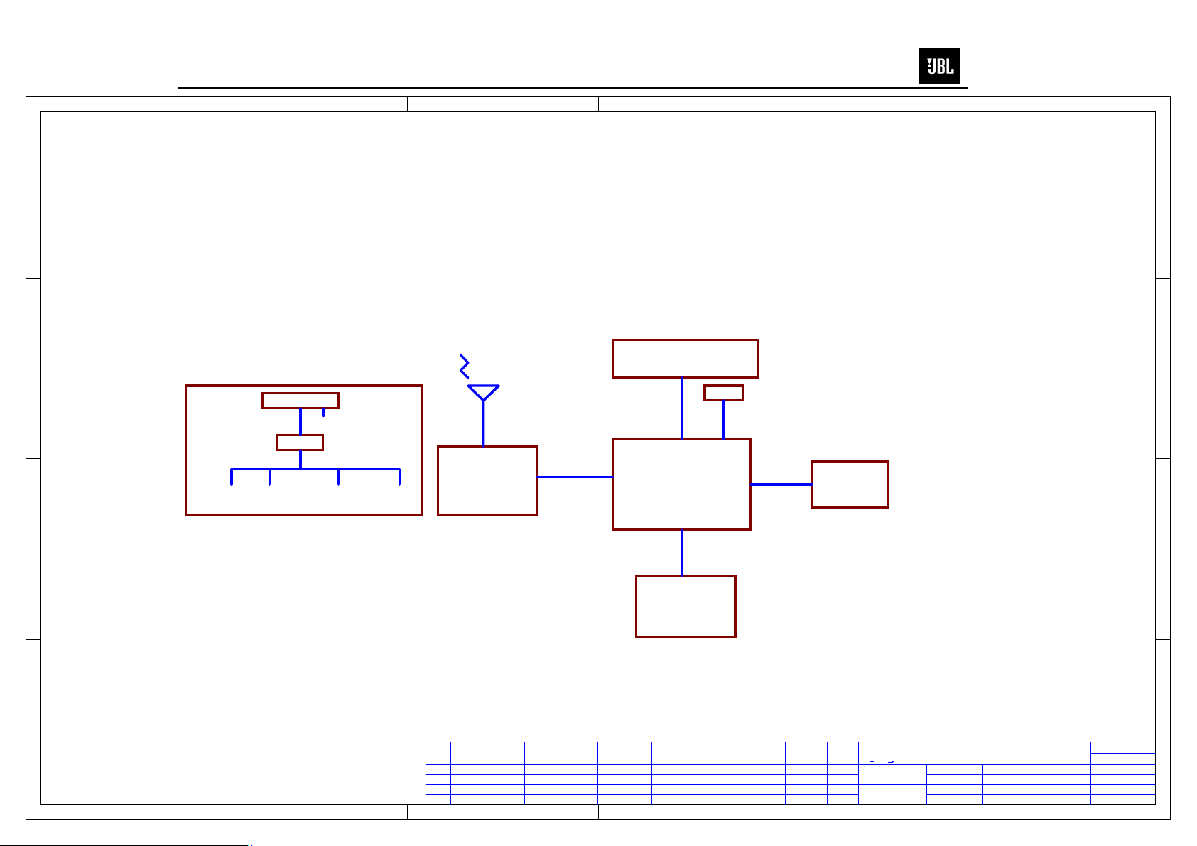
MS-8
D
RF
C
POWER 5V
LCD
LED
654321
D
C
LED
3.3V
TRANSCEIVER
nRF24L01
SPI
MICROCONTROLLER
C8051F367
I2C
MAINBOARD
FLASH nRF24L01 MICROCONTROLLERLCD
B
B
FLASH
M25P80
A
DESCRIPTONREV REV
1 2 3 4 5 6
Place
DATA
DESCRIPTON DATAAPPROVED
Place
PART NAME:
Block Diagram
PRODUCT MODE:
MS-8 AUTO DSP DISPLAY
SCALE: 1:1
UNIT: MM
SIZE:
B
REV:
T4
DRAWN BY:
ChengHao 2010.04.03
CHECKED BY:
APPROVED BY:
DW GNO:
PART NO:
DATA:
DATA:
DATA:
Sheet 2 of 3
A
25
MS-8
D
654321
D
UP
C
DOWN
RF
C
PCBLOOP ANTENNA
LEFT
RIGHT
SELECT
MICROCONTROLLER
MC9S08QG8CDTE
SPI
TRANSCEIVER
nRF24L01
MENU
B
MUTE
VOLUMET+
POWER
BATTERY
B
3VDC/CR2032
VOLUMET-
A
DESCRIPTONREV REV
1 2 3 4 5 6
Place
DATA
DESCRIPTON DATAAPPROVED
Place
PART NAME:
Block Diagram
PRODUCT MODE:
MS-8 AUTO DSP RF CONTROLLER
SCALE: 1:1
UNIT: MM
SIZE:
B
REV:
T4
DRAWN BY:
ChengHao 2010.04.03
CHECKED BY:
APPROVED BY:
DW GNO:
PART NO:
DATA:
DATA:
DATA:
Sheet 3 of 3
A
26
MS-8
MS-8 Electrical Parts List
Part Number Description Qty Reference Designator or Application
Resistors
W-0701-1100-03 Resistor SMD 10Ω 1/10W ±1% 0603 1 R264
W-0701-1330-03 Resistor SMD 33Ω 1/10W ±1% 0603 7 R279,R294,R295,R296,R299,R320,R321
W-0701-4330-02 resistor array SMD 33Ω*4 1/10W ±5% 0603 10 RN1,RN2,RN3,RN4,RN5,RN6,RN7,RN8,RN9,RN10
W-0701-1101-03 Resistor SMD 100Ω 1/10W ±1% 0603 22
W-0701-1241-03 Resistor SMD 240Ω 1/10W ±1% 0603 10 R366,R335,R336,R345,R346,R347,R348,R355,R356,R365
W-0701-1681-03 Resistor SMD 680Ω 1/10W ±1% 0603 1 R232
W-07011698R003 Resistor SMD 698Ω 1/10W ±1% 0603 2 R52,R184
W-0701-1102-03 Resistor SMD 1KΩ 1/10W ±1% 0603 67
W-0701-1152-03 Resistor SMD 1.5KΩ 1/10W ±1% 0603 8 R207,R210,R213,R216,R219,R222,R225,R228
W-0701-1182-03 Resistor SMD 1.8KΩ 1/10W ±1% 0603 8 R206,R209,R212,R215,R218,R221,R224,R227
W-0701-1222-03 Resistor SMD 2.2KΩ 1/10W ±1% 0603 8 R235,R237,R239,R241,R243,R245,R247,R249
W-0703124YK103 Resistor SMD 2.4KΩ 1/10W ±1% 0603 8 R236,R238,R240,R242,R244,R246,R248,R250
W-0701-1332-03 Resistor SMD 3.3KΩ 1/10W ±1% 0603 12 R55,R56,R59,R60,R63,R64,R67,R68,R276,R301,R310,R324
W-0701-1432-03 Resistor SMD 4.3KΩ 1/10W ±1% 0603 10 R2,R5,R373,R374,R375,R376,R377,R378,R379,R380
W-0701-1472-03 Resistor SMD 4.7KΩ 1/10W ±1% 0603 14
W-0701-1512-03 Resistor SMD 5.1KΩ 1/10W ±1% 0603 4 R160,R164,R165,R251
W-0701-1103-03 Resistor SMD 10KΩ 1/10W ±1% 0603 61
W-0701-1243-03 Resistor SMD 24KΩ 1/10W ±1% 0603 1
W-0701-1203-03 Resistor SMD 20KΩ 1/10W ±1% 0603 9 R254,R256,R257,R258,R259,R260,R261,R262,R263
W-0701-1402K03 Resistor SMD 402K 1/10W ±1% 0603 1 R168
W-0701136K5003 Resistor SMD 36.5KΩ 1/10W ±1% 0603 1 R253
W-0701148K7003 Resistor SMD 48.7KΩ 1/10W ±1% 0603 1 R300
W-0701-1473-03 Resistor SMD 47KΩ 1/10W ±1% 0603 1 R302
W-0701-1104-03 Resistor SMD 100KΩ 1/10W ±1% 0603 5 R255,R281,R231,R292,R293
W-0701-1474-03 Resistor SMD 470KΩ 1/10W ±1% 0603 2 R163,R38
W-0701-1475-05 Resistor SMD 475KΩ 1/10W ±1% 0603 23
W-0701-1202-03 Resistor SMD 2KΩ
W-07011221XK03
W-07011232XK03 Resistor SMD 2.32KΩ 1/10W ±1% 0603 1 R80
W-07011768XK03 Resistor SMD 7.68KΩ 1/10W ±1% 0603 1 R81
W-0701-1267-03 Resistor SMD 2.67K 1/10W ±1% 0603 8 R53,R88,R90,R94,R177,R185,R188,R200
W-0701-1499-03 Resistor SMD 4.99K 1/10W ±1% 0603 1 R203
W-0701127R4003 Resistor SMD 27.4KΩ 1/10W ±1% 0603 1 R289
W-0701-1283-03 Resistor SMD 28KΩ 1/10W ±1% 0603 2 R175,R176
W-0701-1475-03 Resistor SMD 1/10W 47.5KΩ ±1% 0603 2 R27,R42
W-0701-1285-03 Resistor SMD 2.8M 1/10W ±1% 0603 1 R162
W-0701156K2003 Resistor SMD 56.2KΩ 1/10W ±1% 0603 16
W-0701-1822-03 Resistor SMD 8.2KΩ 1/10W ±1% 0603 1 R307
W-0701-1634-03 Resistor SMD 63.4KΩ 1/10W ±1% 0603 1 R282
W-0701184K5003 Resistor SMD 84.5KΩ 1/10W ±1% 0603 16
Resistor SMD 2.21K 1/10W ±1% 0603 2 R1,R6
1/10W ±1% 0603 1 R288
R3,R4,R41,R51,R190,R191,R192,R193,R194,R195,
R196,R197,R285,R286,R396,R397,R398,R399,R400,R401,
R402,R403
R28,R47,R48,R170,R204,R265,R266,R267,R268,R269,
R270,R271,R272,R275,R278,R322,R323,R325,R326,R327,
R328,R329,R330,R331,R332,R333,R334,R337,R338,R339,
R340,R341,R342,R343,R344,R349,R350,R351,R352,R353,
R354,R357,R358,R359,R360,R361,R362,R363,R364,R367,
R368,R369,R370,R371,R372,R384,R385,R386,R387,R388,
R389,R390,R391,R392,R393,R394,R395
R7,R8,R26,R30,R202,R234,R252,R273,R274,R277,R280,
R287,R290,R291
R29,R31,R32,R33,R37,R40,R43,R45,R46,R50,R54,R57,
R58,R61,R62,R65,R66,R69,R70,R71,R72,R73,R74,R75,
R76,R77,R78,R79,R89,R91,R103,R158,R167,R169,R173,
R174,R186,R187,R189,R198,R199,R201,R205,R208,R211,
R214,R217,R220,R223,R226,R229,R230,R233,R283,R284,
R298,R382,R383,R34,R39,R297
R9
R92,R93,R95,R96,R97,R98,R99,R100,R101,R102,R104,
R105,R106,R107,R108,R109,R166,R303,R304,R305,R306,
R171,R172
R10,R11,R12,R13,R14,R15,R16,R17,R18,R19,R20,R21,
R22,R23,R24,R25
R82,R83,R84,R85,R86,R87,R110,R111,R112,R113,R114,
R115,R116,R117,R118,R119
Capacitors
W-06S251056045 E-cap SMD 1uF/50V 4*5.4 ±20% 105℃ 3 C2,C28,C178
W-06S254754045 E-cap SMD 4.7uF/25V 4*5.4 ±20% 105℃ 13
C68,C90,C97,C108,C202,C211,C214,C233,C235,C237,
C256,C322,C324
27
MS-8
Part Number Description Qty Reference Designator or Application
C33,C85,C111,C114,C116,C125,C146,C148,C167,C168,
W-06S251064045 E-cap SMD 10uF/25V 4*5.4 ±20% 105℃ 33
W-06S251065055 E-cap SMD 10uF/35V 5*5.4 ±20% 105℃ 7 C374,C375,C376,C377,C378,C380,C392
W-06S252263045 E-cap SMD 22uF/16V 4*5.4 ±20% 105℃ 8 C241,C242,C243,C244,C245,C246,C247,C248
W-06S254761045 E-cap SMD 47uF/6.3V 4*5.4 ±20% 105℃ 4 C35,C36,C51,C107
W-06S254762045 E-cap SMD 47uF/10V 5*5.4 ±20% 105℃ 1 C34
W-06S252273067 E-cap SMD 220uF/16V 6.3*7.7 ±20% 2 C3,C30
W-06S254774011 E-cap
W-06S314706000 Capacitor
W-06S311016000 Capacitor SMD 101/50V 0603 NPO ±5% TDK 16
W-06S312216000 Capacitor SMD 221/50V 0603 NPO ±5% TDK 2 C49,C61
W-06S316816001 Capacitor SMD 681/50V 0603 NPO ±5% 2 C24,C37
W-06S318216000 Capacitor SMD 821/50V 0603 NPO ±5% TDK 16
W-06S331026000 Capacitor SMD 102/50V 0603 NPO ±5% TDK 29
W-06S111036000 Capacitor SMD 103/50V 0603 X7R ±10% TDK 2 C305,C381
W-06S111047000 Capacitor SMD 104/100V 0603 X7R ±10% 1 C1
W-06S111046002 Capacitor SMD 104/50V 0603 X7R ±10% 90
W-06S412246000 Capacitor
W-06S132246000 Capacitor SMD 224/50V 1206 X7R ±10% 20
W-06S114744000 Capacitor SMD 474/25V 0603 X7R ±10% 16
W-06S121056000 Capacitor SMD 105/50V 0805 Y5V +80%/- 2 C63,C208
W-06S122253000 Capacitor SMD 225/16V 0805 X7R ±10% 4 C112,C147,C172,C206
W-06S122254000 Capacitor SMD 225/25V 0805 X5R ±10% 2 C177,C191
W-06S131063001 Capacitor SMD 106/16V 1206 X7R ±10% TDK 1 C297
W-06S134761001
W-06D214785001 E-cap
W-06S121046000 Capacitor SMD 104/50V 0805 X7R ±10% 1 C379
W-06S251074067 E-cap
tantalum
capacitor
SMD 470uF/25V 10*10.2 ±20%
105℃
SMD 47pF/50V 0603 NPO ±5%
TDK
SMD 224/50V 0603 Y5V +80%/20%
SMD 476/6.3V ±10% 1206 AVX 1 C278
DIP 4700uF/35V ±20% 20*30mm
105℃10mm
SMD 100uF/25V 6.3*7.7 ±20%
105℃
C169,C171,C182,C187,C192,C194,C195,C196,C197,C198,
C222,C227,C228,C229,C306,C307,C308,C309,C310,C311,
312,C313,C325
4 C26,C129,C173,C302
C69,C70,C71,C72,C73,C74,C75,C76,C77,C78,C79,C80,
104,C105,C106,C117,C118,C119,C120,C121,
52
C122,C123,C124,C130,C131,C132,C133,C134,C135,C136,
C137,C138,C139,C140,C141,C142,C143,C144,C145,C151,
C152
C258,C260,C262,C264,C266,C268,C270,C272,C387,C388,C3
89,C390,C393,C394,C395,C400
C257,C259,C261,C263,C265,C267,C269,C271,C281,C283,
C285,C287,C289,C291,C293,C295
C4,C5,C6,C65,C92,C98,C110,C115,C205,C209,C226,C240,C
251,C357,C358,C359,C360,C361,C362,C363,C364,C366,
C27,C29,C126,C127,C128,C149,C150,C170,C174,C181,
C188,C189,C190,C193,C199,C203,C207,C210,C215,C216,
C217,C218,C219,C230,C234,C236,C238,C239,C249,C252,
C253,C254,C255,C273,C274,C275,C276,C277,C279,C280,
C299,C300,C301,C303,C304,C314,C315,C316,C317,C318,
C319,C320,C321,C323,C326,C327,C328,C329,C330,C331,
C332,C333,C334,C335,C336,C337,C338,C339,C340,C341,
C342,C343,C344,C345,C346,C347,C348,C349,C350,C351,
C352,C353,C354,C35,C356,C365,C382,C391,C401,C200
C47,C48,C50,C52,C62,C64,C66,C67,C109,C201,C204,
14
C298,C99,C100
C39,C40,C41,C42,C43,C44,C45,C46,C53,C54,C55,C56,
C86,C87,C88,C89,C91,C93,C94,C96,C212,C213,C220,
2 C38,C95
2 C113,C250
C221,C224,C225,C231,C232
C81,C82,C83,C84,C383,C384,C396,C397,C101,102,C103,C
C367,C368,C369,C370,C371,C372,C373
C57,C58,C59,C60,C398,C399,C385,C386
Semiconductors
W-0100-3681-01 IC
W-0100-7563-01 IC
W-04ZL-6A10-00 Diode DIP 6A10 1000V 1 D34
W-01TI-610B-00 IC
W-0100-5358-00 IC
DIP TDA3681J 17-PIN SOT243-3
Multiple voltage regulator NXP
DIP TDA7563B Flexiwatt 27 4 x
50W multifunction quad power
amplifier
SMD TMS320DA610B-GDP
FLOATING-POINT DIGITAL
SIGNAL PROCESSOR TI
SMD AK5358AET TSSOP-16 96kHz
24 bit ADC AKM
1 U4, NXP designated
2U3、 U17, STM designated
1 U21
4 U5, U6, U13, U14
-
28
MS-8
Part Number Description Qty Reference Designator or Application
W-01TI-CU04-09 IC
W-0100-0741-09 IC
W-01TI-3106-00 IC
W-0100-3262-00 IC
W-01SL-8051-AA IC
W-0100-M224-00 IC
W-0100-4359-02 IC
W-0100-974I-02 IC
W-0100-4052-02 IC
W-0100-2244-02 IC
W-0100-2734-02 IC
W-01LT-1694-05 IC
W-0100-016M-AA IC
W-04WY-15BV101 Diode SMD 15V DO-213AA 0.5W 1 D33
W-04PT-AV70-15 Diode SMD BAV70 SOT-23 NXP 12 D1, D4, D6, D8, D10, D11, D13, D15, D17, D25, D27, D29
W-03T1-AW56-04 Diode SMD BAW56 SOT-23 11 D3, D5, D7, D9, D12, D14, D16, D18, D26, D28, D30
W-04WY-BZX8-15 Diode
W-04XT-RS06-00 Diode
W-04WY-56AV100 Diode
W-03T0-358P-04 Mos FET
W-03T0-301N-04 Mos FET
W-04PT-0603-00 ESD Diode SMD: MLSEP24B-0603 SEMITEL 44 SX1-SX44
W-04WY-22BV102 Diode SMD 22V DO-214AB SMLJ22A-T 1 D2
W-04PT-4148-11 Diode SMD 1N4148 SOD-123 3 D19, D20, D23
W-03N3-3904-04 Transistor
W-03N1-2114-04 Transistor
W-03P2-3906-04 Transistor
W-03N0-5214-21 Transistor
W-2004-0022-00 LED DIP Φ3 blue 1 LED1
SMD 74HCU04 TSSOP-14 package
Hex Inverter TI
SMD TL074ID SOIC-14 package
Quad Op-Amp TI
SMD TPS3106K 33DBVR SOT-23
UltraLow Supply-Current/SupplyVoltage Supervisory TI
SMD MT48LC2M32B2-7-1T2 86PIN TSOP Synchronous DRAM
SMD C8051F347-GQ LQFP32 Full
Speed USB Flash SILICON LABS
SMD LM224 SOIC-14 Quad OpAmp
SMD AK4359VF VSOP30package192kHz 24 bit 8chan
DAC AKM
SMD TS974IPT TSSOP-14 LoNoise Op-Amp
SMD 74HC4052 TSSOP-16package
Dual 4-chan
multiplexer,demultiplexer
SMD 74LVC2244A TSSOP-20 Octal
buffer/line driver 3-state
SMD LM2734Y DC/DC TSOT-6 1A
Load Step-Down DC-DC Regulator
SMD LTC1694IS5 SMBus/I2C
Accelerator SOT-23 LINEAR
TECHNOLOG
SMD S29AL016M90TFI01 16 MBit
3.0 V Boot Sector Flash Memory
TOSP48 (programmed)
SMD BZX84C3V9 ZENER 3.9V
SOT-23
SMD CRS06 Schottky Barrier
Rectifier
SMD 5.6V SC-74A FTZ5.6E 5pins
ROHM
SMD FDN358P P-Ch Logic Level
Enhancement FET SOT23
FAIRCHILD
SMD FDV301N Digital FET NChannel SOT23 FAIRCHILD
SMD MMBT3904 NPN SOT-23
brand:ON
SMD 2SD2114K SOT23 NPN
TRANSISTOR, Brand: ROHM
SMD MMBT3906 PNP SOT-23
brand:ON
SMD MUN5214T1 NPN SC-70/SOT
323 ON
2 U10, U16
5 U28, U31, U35, U38, U39
1 U26
1U7
1 U23
1 U12
1U9
3 U2, U19, U20
1 U15
1 U22
1 U24
1 U25
1 U8, SPANSION designated
1 D24
1 D22
2 DP2, DP3
1Q4
3 Q1, Q5, Q32
Q9, Q10, Q29, Q30, Q33, Q34, Q35, Q36, Q37, Q38, Q39,
14
8 Q21, Q22, Q23, Q24, Q25, Q26, Q27, Q28
Q2, Q8, Q11, Q12, Q13, Q14, Q15, Q16, Q17, Q18, Q19, Q20,
13
Q31
1Q3
Q40, Q41, Q42
Miscellaneous
W-05RP-1210-02 Thermistor
W-05RP-035F-01 Thermistor SMD microSMD035F 6.0Vdc 40A 1 RT2
W-05RN-1031-01 Thermistor
DIP PTC 120Ω P/N:238166056393
VISHAY
SMD NTC 10K ±5%
NCP18XH103J03RB 0603
brand:Murata
8 RT3,RT4,RT5,RT6,RT7,RT8,RT9,RT10
1 RT11, Murata designated
29
MS-8
Part Number Description Qty Reference Designator or Application
W-ZA-H00010101 Bracket
W-DB-800010015 Lens
W-SG-0002-0111 Top cover
W-XG-0005-0101 Bottom
W-MK-0009-0101 Input Board
W-MK-0010-0101 Output Board
W-LS1AY0300601 Screw 3*6MM 9 Screw the PCBA, Input Board and Output Board to the bottom
W-LS1KM0040071 Screw 4*7MM 8 Screw the Bracket to the bottom
W-LS1AY0401201 Screw 4*12MM 4 Screw the top cover to the bottom
W-LS1BM0040081 Screw 4*8 MM 3 Screw the top cover to heatsink
W-1001-6500-10 HF inductor 65UH CL-7200 Φ30 1 L20
W-1360-0004-00 Tact Switch DIP 4PIN H=4.3MM TC00100 1 SW1
W-1400-0026-00 USB Jack DIP 4PIN USB-109 1 J5
W-1400-0028-00 Terminal JSZ4-01AN 1 TB1
W-1404-0006-00 RCA Jack
W-1404-0008-00 RCA Jack
W-1404-0028-02 RCA Jack
W-1501-0800-00 Jack DIP 39-30-1160/3.96 8P 2 J3、 J6
W-1503-0700-00 needle stand
W-1401-0004-00 Fuse holder BXS-09 1 for F1
W-1601-253G-01 Fuse DIP 25A/32V LittelFuse 1 F1
W-1003-0004-08 Inductor SMD 1NH 0805 ±0.3NH 6 L17、L18、L19、 L21、L23、L24
W-1003-1500-00 Inductor SMD 15uH ±5% 2A SMRH74-150M 1 L22
W-18SM-2400-00 Crystal
W-1400-0024-00 Jack SJ-42524-SMT 1 J8
W-1400-0025-00 Microphone Jack SMD 5PIN Φ3.5mm Jack 1 J1
W-1004-1020-08 Inductor
W-LS1AM0300607 Screw PM3*6 8
248.6*38mm ADC-12 black texture
paint
232*48*4MM PC transparency with
silkscreen and paint
294*162.4*52.5MM ADC-12 diacasting, silver paint and logo with
diamond cut
290.4*158.8*46.5MM ADC-12, diacasting, black texture paint
229.6*32.3mm SECC, 1.6t, black
texture paint with silkscreen
229.6*32.3mm SECC, 1.6t, black
texture paint with silkscreen
AV8-8.4-13AN(WR)8 Jacks, 16
PINS, black
AV8-8.4-13AN(WR)8 Jacks, 16
PINS, White
AV2-8.4-13AN(WR) 2 Jacks, 4
PINS, white and red
TM-2008-AG-14/2.54 14P( double
7P)
SMD ASSVP-24.576MHZ-C04-T
ABRACONbrand
SMD 1KΩ 0805 FBMA-11-201209102T
2
1
1
1
1
1
1J7
1J2
1 J11
1J9
1Y1
4 L25、L26、L27、L28
Screw the SUB Heatsink (A)/(B) to the PCBA
W-LS1BE0301607 Screw 3*16 6 Screw the SUB Heatsink A/B to the bracket
W-SR-MS80-0325 SUB Heatsink B
W-SR-MS80-0425
W-ZA-B00120100 IC Bracket A
W-ZA-B00130100 IC Bracket B 26.5*21.1*10MM EGI,1.0T/TDA7563 1 Instal to the SUB Heatsink B
W-ZL-10002A-35 LED Spacer 7.4*4.6*6.5 NYLON66 Black 1 Instal to the PCBA
W-LS1AJ0301001 Srew 3*10MM 9 Screw the RCA JACK/TRERMINAL to side board
W-JD-B40600515
SUB Heatsink A
tcp thermally
conductive pad
31*35*27.9MM Alum. Extrusion,
AL6063
98*35*27.9MM Alum. Extrusion,
AL6063
31.5*23.1*10MM EGI,1.0T
/TDA3681
Φ12*3MM 3 Install to the screw hole of the bottom
1 Instal to the IC on the left side of the PCBA
1 Instal to the IC on the right side of the PCBA
2 Instal to the SUB Heatsink A
 Loading...