

Page 1
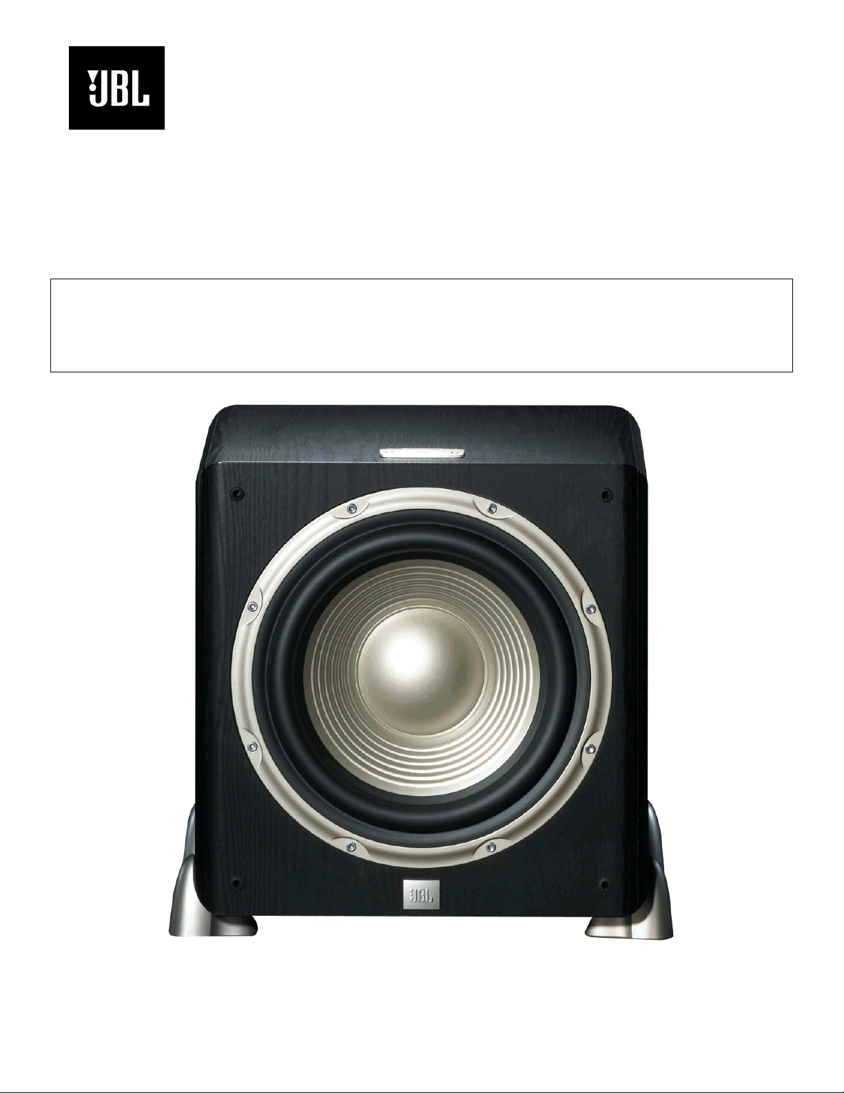
Studio L Series
L8400P
Amplifier/Subwoofer
SERVICE MANUAL
JBL Consumer Products
250 Crossways Park Dr.
Woodbury, New York 11797 Rev1 3/2006
Page 2

L8400P L series
1
- CONTENTS -
BASIC SPECIFICATIONS…………………………………………..1
PACKAGING…………………………….……………….………….2
DETAILED SPECIFICATIONS…………………………………….3
CONNECTIONS..………………………………………………….. 5
OPERATION ………….…………………………..….….………….7
BASIC TROUBLESHOOTING…………………………………….8
EXPLODED VIEW……………………………………………….…9
120V BLOCK DIAGRAM..……………………………………..….10
PCB DRAWINGS………………..………………………………...11
120V ELECTRICAL PARTS LIST …………….…….…………..15
INTEGRATED CIRCUIT/TRANSISTOR PINOUTS………....19
120V SCHEMATICS.……….………………………..…. ………20
L8400P BASIC SPECIFICATIONS
Amplifier Power ( RMS) 600 Watts
Peak Dynamic Power * 1200 Watts
Frequency Response (–3dB) 22Hz – Low-pass crossover frequency
Low-Pass Crossover Frequencies 50Hz – 150Hz, Continuously adjustable
Low-Frequency Transducer 12" (300mm) PolyPla s ™ cone
Baffle Low diffraction, IsoPower™
Enclosure Sealed
Inputs Gold-plated 5-way binding-post speaker-level;
Left and right line-level, switchable to LFE
Outputs 150Hz when using speaker-level connection
Gold-plated 5-way binding-posts
Dimensions (H x W x D) 16-1/2" (15-1/2" without feet) x 15-1/2" x 15-1/2"
(419mm [394mm without feet] x 394mm x 394mm)
Weight 58 lb (26.4kg)
* The Peak Dynamic Power is measured by recording the highest peak-to- c enter v oltage produced by t he power
amplifi er with its limiters disabled, across the output of a resistiv e load equal to minimum impedance of the
transducer, using a 50Hz sine wavebur st, 3 cycles on, 17 cycles off.
Occasional r efinements may be made to existing product s without notice but will always meet or exceed original
specifications unless otherwise stated
Page 3
L8400P
Packaging
5
6
6
1 3 4 7 8
2
2
ITEM
NO. DESCRIPTION QTY. PART NO.
1. Owner’s Manual 1 354038-001
2. Front Grille 1 353234-001
3. Warranty Card, JBL 5YR/1YR 1 338381-001
4. Kit, Spike Foot 4 354432-001
5. L8400P Outer Carton, Black 1 353588-001
L8400P Outer Carton, Beech 1 353588-002
L8400P Outer Carton, Cherry 1 353588-003
ITEM
NO. DESCRIPTION QTY. PART NO.
6. Pad, Foam, Top, Bottom L8400P 2 353592-001
7. Y-Adapter Cable 1 354058-001
8. Foot, Bump-On 3M, SJ5744 4 330104-001
Page 4
y
e
L8400P L series
3
L8400P Powered Sub/ Plate Amp
LINE VOLTAGE Yes/No Hi/Lo Line Nom. Unit Notes
Parameter Spec. Unit
Amp Section
Type (Class AB, D, other) D n/a
Load Impedance (speaker) 4 Ohms
Rated Output Power 450 Watts
THD @ Rated Power 0.5 %
THD @ 1 Watt 0.1 %
Dynamic Power 460 Watts
DC Offset 80 mV-DC
Damping factor >20 DF
Input Sensitivit
Input Frequency 50 Hz
Left or Right inputs 16.6 mVrms
Left & Right with LFE or LP
filter OFF Mode selected
Speaker/Hi Level Input 165 mVrms
US 120VAC/60Hz Yes 108-132 120
EU 230VAC/50-60Hz Yes 207-264 230
QA Test
Limits Conditions Notes
±2dB To 1 Watt
16.6 mVrms
±2dB To 1 Watt
±2dB To 1 Watt
Vrms Normal Operation
Vrms Normal operation, MOMS required
Bridge type amplifier, None of the speaker
n/a
n/a Nominal
380 1 input driven Measuring 425 Watts Cold
1 22K filter
0.2 22K filter
Power is the average measurement
of the first four consecutive peaks
450
of the burst signal
100 @ Speaker Outputs
15 Measured at amplifier board
30 Nominal Freq.
terminals must be connected to system
GND at any time.
3/20 Cycles @ 50 Hz, burst test into 4
Ohms, input driven 6dB above its maximum
sensitivity, volume level at Maximum.
Measured at the speaker cable. 200 Watts,
measured at speaker output terminals
located at the amp board.
Single input driven, Ap Zo=600 Ohms, LP
ON, Volume ctrl & crossover at max
Single input driven , Ap Zo=600 Ohms, LP
OFF, Volume ctrl & crossover at max
Single input driven, Ap Zo=25 Ohms,
Normal, Volume ctrl & crossover at max
Signal to Noise
SNR-A-Weighted 100 dBA
SNR-unweighted 95 dBr
SNR rel. 1W-unweighted 70 dBr
Residual Noise Floor 0.5 mVrms
Residual Noise Floor 0.5 mVrms(max)
Speaker input rejection
CMRR Speaker in >37 dB
Input Impedance
Filters
LP 4th order variable 50-150 Hz
Subsonic filter (HPF) 3rd Ord
Low pass filter OFF Fixed Hz
HP Speaker output 4 Ohms 200 Hz
HP Speaker output 8 Ohms 100 Hz
Line Input (L, R,LFE) 10K ohms
Speaker/Hi Level Input 10K ohms
Fixed Hz
90 Relative to rated power (400 Watts) A-Weighting filter
85 Relative to rated power (400 Watts) 22K filter
65 Relative to 1W Output 22K filter
Volume @max, using RMS reading
1
DMM/VOM (or A/P)
Volume @max, w/ A/P Swept
Bandpass Measurement (Line
1
freq.+ harmonics)
1.0V + RMS applied to + & - inputs
Reference
± 10
± 10
± 20 L or R input driven, LP Filter OFF
± 10 Speaker output loaded with 4 Ohms
± 10 Speaker output loaded with 8 Ohms
50 Hz, Generator GND to system
GND
n/a Nominal
n/a Nominal
Limiter
THD at Max. Output Power
Features --
Auto - On -Off YES --
YES n/a functional
functional
No switch to select the ATO mode is
provided, Refer to ATO section
Page 5
-
y
L8400P L series
4
QA Test
Parameter Spec. Unit
Amp Section
Phase switch 0-180 deg
Volume pot Taper (lin/log) LOG --
Variable crossover 50-150 Hz YES
Limits Conditions Notes
functional
functional 5K A Taper
functional
4th Order LP Filter, 2nd order fix and 2nd
order variable.
HP Speaker out YES
LP On- Off Select switch YES --
On-Off indicators
Input Configuration
Line In (L,R) & LFE
Spkr/Hi Level In YES --
Signal Sensing (ATO)
Auto-Turn-On (yes/no) YES
ATO Input test frequency 50 Hz
Min ATO Level L or R Inputs 3 mV
Min ATO Level Speaker in L
or R inputs
ATO Turn-on time 2 seconds
Auto Mute/ Turn-OFF Time 5 minutes
Auto Mute/ Turn-OFF Time 15 Minutes
Power on Delay time 2 sec.
Transients/Pops
ATO Transient 5 mV-peak
Turn-on Transient 50 mV-peak
Turn-off Transient 50 mV-peak
YES
YES --
30 mV
functional Pass through from the speaker input section
functional Disables LP filter, intended for LFE
functional
functional Dual RCA jack, L or R is used in LFE mode
functional Binding post connector L&R
functional Auto - on selection switch in Auto
functional "
functional " Single input driven
functional " Single input driven
functional
1V-pk-pk @ Speaker Outputs AC Line cycled from OFF to ON
1V-pk-pk @ Speaker Outputs AC Line cycled from ON to OFF
Amp connected and AC on, then
input signal applied
(T) Time before muting, after
minimum ATO signal is removed
17
(3mV)
(T) Time before muting, after input
17
signal is removed
4 AC Power Applied
n/a @ Speaker Outputs
Unit is provided with 2 LED's BLU-ON, RED
OFF
Auto turn of time (T) must be 5 > T < 17
Minutes
Auto turn of time (T) must be 10 > T < 17
Minutes
Efficienc
Efficiency 68 %
Stand-by Input Power 18 Watts
Stand-by Input Power 22 Watts
Power Cons. @ 400W 584 Watts
Protection
Thermal Protection YES
DC Offset Protection YES
Line Fuse Rating
USA-Domestic 5 Amps
EU 2.5 Amps
65 400W of output power Nominal Line voltage 120 VAC
@ nominal line voltage, Amp in
20
OFF state, RED LED activated
@ nom. line voltage, Amp in On
25
state, Green LED activated
615 @ nom. line voltage 400 Watts into 4 Ohms nominal line voltage
functional @1/8 max unclipped Power
- DC present at Speaker Out leads Relay opens during a DC output condition
Type-T or Slo Blo-250 V
Type-T , Low Breaking capacity-250
V Internal fuse with UL/SEMKO rated holder
Maximum allowable input power LED in
RED, Class D inactive
Maximum allowable input power under
nominal Input voltage and frequency, in
stand-by mode (HOT or COLD operation,
LED GREEN). Class D active but no signal
applied.
Temperature rise in accessible metal parts
should not exceed 35K rise for domestic
version or 30K rise for European versions
(refer to requirements sheet). Unit is
protected for over-temperature conditions
Page 6
L8400P L series
5
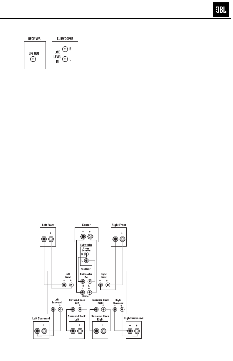
DOLBY* DIGITAL OR DTS
(OR OTHER DIGITAL SURROUND MODE) CONNECTION
Use this installation method for
Dolby Digital, DTS or other digital surround processors:
Use either the left or right linelevel input jack for the LowFrequency Effects channel; it
doesn’t matter which one you
choose.
DOLBY PRO LOGIC* (NON-DIGITAL) –LINE LEVEL
Use this installation method
for Dolby Pro Logic applications (not Dolby Digital, DTS
or other digital processing),
where the receiver/processor
is equipped with a subwoofer
output, or a volume-controlled
preamp (line-) level output:
Use RCA-type interconnects
to connect the line-level
subwoofer outputs on your
receiver or amplifier to the
line-level inputs on the sub-
®
IMPORTANT: Make sure that
the LFE/Normal toggle switch
∞ is in the “LFE” position.
This will bypass the subwoofer’s normal low-pass
filter, reducing the possibility
of signal degradation and more
accurately reproducing the
program materials. However, if
your receiver is passing a fullrange signal through its subwoofer output, place the toggle switch in the “Normal”
position, which will activate
the low-pass filter and protect
woofer. IMPORTANT: Make
sure that the LFE/Normal
toggle switch ∞ is in the
“Normal” position. This will
activate the subwoofer’s lowpass filter, protecting the subwoofer from possible damage
and enabling it to operate most
efficiently by reproducing only
the low-frequency materials
that it is best at handling.
NOTE: If your receiver or
amplifier only has one sub-
the subwoofer from possible
damage. Connect this jack to
the LFE output or subwoofer
output on your receiver or
amplifier. Connect each
speaker to the corresponding
speaker terminals on your
receiver or amplifier.
Make sure that you have configured your surround sound
processor for “Subwoofer On.”
Also, remember to configure
your receiver for 5.1-, 6.1- or
7.1-channel operation as
appropriate.
woofer output jack, then you
will need to use a Y-connector
(not included). Plug the male
end of the Y-connector into
your receiver or amplifier’s
subwoofer output jack, and
connect each of the two
female ends to separate RCAtype interconnects. Finally,
plug the RCA-type interconnects into the line-level inputs
on the subwoofer.
Connect each speaker to
the corresponding speaker
terminals on your receiver
or amplifier.
Make sure your receiver or
processor is correctly configured to indicate that the subwoofer is “On.”
Note for advanced users: If
your receiver/processor has
a built-in low-pass crossover
filter for the subwoofer output,
you may switch the LFE/
Normal toggle switch to the
“LFE” position to bypass the
subwoofer’s internal
crossover.
4
Page 7
L8400P L series
6
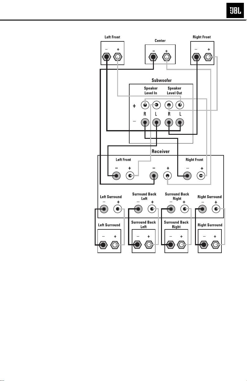
DOLBY PRO LOGIC (NON-DIGITAL) –SPEAKER LEVEL
Use this installation method
for Dolby Pro Logic applications (not Dolby Digital, DTS
or other digital processing),
where the receiver/processor
does not have a subwoofer
output, or a volume-controlled
preamp (line-) level output:
Connect your receiver or
amplifier’s front left and right
speaker terminals to the left
and right terminals on the
subwoofer that are marked
“Speaker Level In.” Connect
the left and right terminals
on the subwoofer that are
marked “Speaker Level Out” to
the corresponding terminals on
the back of your front left and
right speakers.
Connect your receiver or
amplifier’s center, surround
and surround back speaker
terminals to the corresponding
terminals on the back of
your center and surround
speakers.
5
Page 8
L8400P L series
7
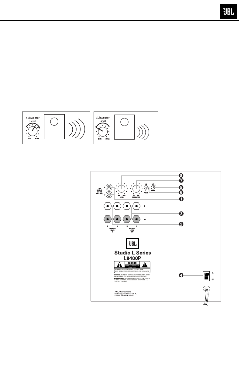
OPERATION
Power
Move the Master Power
¢ to the “On” position to use
the L8400P subwoofer.
Level Control
The subwoofer Level Control
• adjusts the volume of the
subwoofer relative to the rest
of the system. Proper level
Crossover Adjustments
The Crossover Frequency
Control ¶ determines the
highest frequency at
subwoofer reproduces
If your main speakers can
comfortably reproduce some
low-frequency sounds, set this
control to a lower frequency
setting, between 50Hz and
100Hz. This will concentrate
the subwoofer’s efforts on
the ultradeep bass sounds
required by today’s films and
music. If you are using smaller
bookshelf speakers that do not
extend to the lower bass frequencies, set the low-pass
crossover control to a higher
setting, between 120Hz and
150Hz. This control is not used
when the LFE switch ∞ is in
the “LFE” position.
switch
which the
sounds.
If you will be away from home
for an extended period of time,
or if the subwoofer will not be
adjustment depends on several variables such as room
size, subwoofer placement,
type of main speakers and
used, switch the Master
Power switch ¢ to the “Off”
position.
position. Adjust the subwoofer
level so that the volume of the
bass information is pleasing
to you.
6
Page 9

L8400P L series
8
Phase Control
The Phase Control § determines whether the subwoofer’s pistonlike action
moves in and out in phase
with the main speakers or
opposite the main speakers.
There is no correct or incorrect setting. Proper phase
adjustment depends on several variables such as subwoofer placement and listener position. Adjust the
Phase switch to maximize
bass output at the listening
position.
Remember, every system,
room and listener is different.
There are no right or wrong
settings; this switch offers the
added flexibility to adjust your
subwoofer for optimum performance for your specific
listening conditions without
TROUBLESHOOTING
If you used the high-level
(speaker) inputs and there
is no sound from any of the
speakers:
•
Check that the receiver/
amplifier
is on and a source
is playing.
• Check that the powered
subwoofer is plugged into
an active electrical outlet
and is switched on.
• Check all wires and connections between the receiver/
amplifier and the speakers.
Make sure all wires are connected. Make sure none of
the speaker wires are frayed,
cut or punctured, or touching
each other.
• Review proper operation
of your receiver/amplifier.
If there is low (or no) bass
output:
• Make sure the connections
to the left and right “Speaker
Inputs” have the correct
polarity (+ and –).
• Make sure that the subwoofer is plugged into an
active electrical outlet and
switched on.
• Adjust the crossover point.
• Flip the Phase Control switch
to the opposite position.
• If you are using a Dolby
Digital/DTS receiver or
processor, make sure that the
subwoofer and bass management adjustments on the
receiver/processor are set up
correctly.
• Slowly turn the Level Control
clockwise until you begin to
hear the desired amount of
bass.
having to move your speakers.
If at some time in the future
you happen to rearrange your
listening room and move your
speakers, you should experiment with the Phase switch in
both positions, and leave it in
the position that maximizes
bass performance.
If you used the line-level
inputs and there is no sound
from the subwoofer:
•
Check that the receiver/
amplifier
is on and a source is
playing.
• Check that the powered
subwoofer is plugged into an
active electrical outlet and is
switched on.
• Check all wires and
connections between the
receiver/amplifier and the
subwoofer. Make sure all
wires are connected. Make
sure none of the wires are
frayed, cut or punctured, or
touching each other.
• Review proper operation of
your receiver/amplifier.
• Slowly turn the Level
Control clockwise until you
begin to hear the desired
amount of bass.
• Make sure that you have
configured your receiver/
processor so that the subwoofer/LFE output is on.
7
Page 10
L8400P
Exploded View
11
5
8
7
2
9
1
1
2
6
3
10
4
9
ITEM
NO. DESCRIPTION QTY. PART NO.
1. Woofer Assembly 12" DCR=3.7Ω ±10% 1 353112-001
2. Front Grille 1 353234-001
3. Grille Cup, BLK 4 333249-001
Grille Cup, BE & CH 4 333249-003
4. LED Wire Assembly 1 354288-001
5. Plate LED 1 353356-001
6. Gasket, Plate LED 1 353589-001
ITEM
NO. DESCRIPTION QTY. PART NO.
7. Assembly, Foot 4 353354-001
8. Assembly, Logo 1 353284-001
9. Screw (Foot) #8 X 1, PB, TRPH CR BLK 8 903101-016
10. Screw (Woofer) #8 X 3/4," PB, HXS, ZINC 8 903802-012
11. Screw (Amplifier) #8 X 1, PPH, PB, BLK 12 900101-016
12. Screw (LED Plate) #6 X 3/4," PB, HXS, ZINC 4 908302-012
Page 11

L8400P L series
10
L8400P BLOCK DIAGRAM
Page 12
L8400P L series
11
NOTE: DESIGNAT OR S ARE WRONG
(SWAPPED) FOR L8 AND L11.
BOTH DRAWING AND ACTUAL PCB
ON MODEL FIFTEEN
Page 13

L8400P L series
12
Page 14
L8400P L series
13
Page 15

L8400P L series
14
Page 16

r
r
B
6
E
s
5
5
)
)
)
)
2
)
)
)
E
E
m
)
s
8
)
7
)
)
6
)
L8400P L series
15
L8400P (120v) ELECTRICAL PARTS LIST
Part Numbe
Main Amp/Supply PC
Resistors
024-000098-120 GS SMD resistor 0R 1/8W J 0805 (R8) R8 1
024-100498-120 SMD resistor 1K 1/8W J 0805 (R110) R110 1
024-100598-120 GS SMD resistor 10K 1/8W J 0805 ()
024-100698-120 GS SMD resistor 100K 1/8W J 0805 (R15,120) R15,120 2
024-110598-120 SMD resistor 11K 1/8W J 0805 R187,188,190,191 4
024-130498-100 SMD resistor1K3 1/8W F 0805 R189,192 2
024-150598-120 SMD resistor 15K 1/8W J 0805 (R20,21) R20,21 2
024-160598-100 SMD resistor 16K 1/8W F 0805 (R13,13B) R13,13B 2
024-220298-120 SMD resistor 22R 1/8W J 0805 (R28,29) R28,29 2
024-220498-120 SMD resistor 2K2 1/4W J 1206 (R119) R119 1
024-220498-121 SMD resistor 2K2 1/8W J 0805 (R17,31) R17,31 2
024-220598-120 SMD resistor 22K 1/8W J 0805 (R127) R127 1
024-330498-120 SMD resistor 3K3 1/8W J 0805 (R77,79,22,) R77,79,22 3
024-330598-120 SMD resistor 33K 1/8W J 0805 (R4,6,14,60,60B) R4,6,14,60,60B 5
024-412498-100 SMD resistor 4K12 1/8W F 0805 (R63) R63 1
024-470298-120 GS SMD 47R 1/8W J 0805 (R24-27) R24-27 4
024-470398-120 GS SMD resistor 470R 1/8W J 0805 R145,155,177,18
024-470598-120 GS SMD resistor 47K 1/8W J 0805 (R3,171) R3,171 2
024-510498-120 SMD resistor 5K1 1/8W J 0805 R48A,48B,48C,48D,48
024-560498-120 GS SMD resistor 5K6 1/8W J 0805 R30,169 2
024-680498-120 GS SMD resistor 6K8 1/8W J 0805 (R23) R23 1
021-100401-020 MOF Resistor 1K 1W J FK TYPE R173 1
021-560305-020 MOF resistor 560R 5WS J 8x25 KINK R76 1
022-005105-020 GS Resistor PN:SQM 0R05 5W J 25x13 R2 1
022-470307-020 Resistor KNP 470R 7W J (KNP-700S) R78 1
Description Reference Designato
R5,7,16,118,121,122,125,1,126,128,138,165,17
0,168,139
Qty
15
4
5
Capacitor
034-100614-300 Electrolytic cap. 100uF/16V M (R)0611 P:2.
034-100625-300 Eletrolytic cap. 100uF/25V M (R)6.3x11 P:
034-100695-300 electrolytic 100uF/63V M (R)1012 P:5 (
034-220525-300 GR Eletrolytic 22uF/25V M (R)5x11 P:2.5 TAPIN(
034-330625-300 GS Eletrolytic 330uF/25V M (R)1013 P:5 (
034-470415-300 Electrolytic cap. 4u7/50V M (R)0511 P:2.0 () C7 1
031-100184-100A SMD Cap. 0u01/250V K 0805 X7R C104,119 2
031-100244-100A SMD Ceramic Cap. 0u01/50V K 0805 X7R (C27,28
031-100344-100A SMD Cap. 0u1/50V K 0805 X7R C115,135,138C,10,69,11
031-100384-100A SMD Cap. 0u1/250V K 1206 X7R (C5,6
031-220344-300A SMD Cap. 220pF/50V K 0805 NPO (C40
031-470144-101A SMD Cap. 0u0047/50V K 0805 X7R (C1G1
033-330444-270 NPE cap. 印ELYTONE 3u3/50V K10 (R)8x13 SB
033-680464-270 NPE cap. 印ELYTONE 6u8/100V K10 (R)1020 GN
034-150895-201 Electrolytic cap. 105℃ 15000uF/63V M (R)3557 P:10m
032-100484-200 GS END mylar cap. 1uF/250V K P:15 (C37,39,30
Semiconductor
051-000600-100 Transistor NPN PN:MPSW06RLRA TO-92 (ON)(Q6) Q6 1
051-005600-100 Transistor PNP PN:MPSW56RLRA TO-92 (ON)(Q8) Q8 1
051-290700-100 Transistor PNP (ON) PN:MPS2907A RLRA TO-92 Q12,14,16,1
051-540101-000 GR Transistor PNP(FAIRCHILD PN:2N5401 TO-92 (Q3
054-000100-100 GS SMD DIODE: PN:ES1D 200V 1A D1,23,37,40,44,4
054-001002-100 SMD ZENER DIODE PN:BZX84C10 10V SOT-23 (D32
054-001501-100 SMD ZENER DIODE PN:BZX84C15 15V SOT-23 (D2,3
054-033904-100 SMD Transistor PN:MMBT3904LT1 SOT23 Q25,28,29,37,50,51 6
054-033906-100 SMD Transistor PN:MMBT3906LT1 SOT23 Q26,27,30,3
054-050601-100 SMD ZENER DIODE PN:BZX84C5V6 5.6V SOT-23 D30 1
054-290701-100 SMDTransistor (ON) PN:MMBT2907ALT1 SOT-23 (Q52
C8 1
C62 1
C142 1
C25,26 2
C11,100 2
C27,28 2
C5,6 2
C40 1
C1G1 1
C114,137 2
C113,136 2
C1,4 2
C37,39,30 3
Q3 1
D32 1
D2,3 2
Q52 1
6
4
6
4
Page 17

r
r
B
)
)
)
7
)
s
6
)
)
)
A
)
)
0
0
9
6
6
s
)
)
)
)
)
0
)
L8400P L series
16
Part Numbe
Main Amp/Supply PC
054-414803-100ZR GR SMD DIODE PN:LL4148GSO8 (Vishay)(
054-540100-100 SMD Transistor (PNP) PN:MMBT5401 LT1 SOT-23 (Q1
054-555100-100 SMD Transistor (NPN) PN:MMBT5551 LT1 (ON)(Q2
051-002301-000 MOSFET N CHANNEL PN:FB23N20D Q11,13,15,1
052-400080-000 Bridge Rectifier PN:RS804 400V,8A (BR1) BR1 1
053-257400-100 IC:DIP,Regulator PN:LM2574 HVN-15V 8PIN (NS)(U6
Miscellaneou
044-100100-000 SMD FERRITE BEAD PN:321611 600R/100MHz 120
025-010300-000 Thermister TSE-103 K L:50mm TH1 1
025-210100-000 Thermister (PTC) PN:PTMS2101RP516B (TH2
043-300101-000 INDUCTOR PN:YT-10033 30uH (L9,10
043-560200-000 INDUCTOR 56uH YT-10779 (L12) L12 1
043-700100-000 INDUCTOR 70uHx2 YT-10024 (L8
043-820300-000 INDUCTOR 820uH YT-10034 (L1) L1 1
072-040008-110 8P Terminal base JS-1001-08 (P1) P1 1
072-040039-000 Terminal (PCB TYPE) PC205 (t=0.8m/m) T205M
072-040064-000 Terminal (PCB TYPE) PC250(t=0.8),T250MA T2,TER6 2
072-040096-000 Terminal T187MA(PCB TYPE) (t=0.8mm) PC187(0.8
073-111003-000 Shorting Strap 54.9x13.6x1mm (J7) J7 1
073-111004-000 Shorting Strap 29.5x12.4x0.8m/m (J4,9
074-300018-000 RELAY PN:943-1C-48D (RLY1) RLY1 1
061-700044-000 Mica 13x18mm TO-220 (Q13,17) for Q13,17 2
061-700090-900 Ceramic washer 16x21mm t=2mm 化 白色 for Q11,15 2
063-010010-000 Bracket for Transistor P/N:TRK-2 for Q11,13,15,17,TH1 5
Description Reference Designato
D4-5,13,14,21,22,31,33,38,41,45,48,34,6,90,91,16
Q1 1
Q2 1
U6 1
FB1,FB2 2
TH2 1
L9,10 2
L8 1
TER5,7 2
J4,9 2
Qty
4
1
Drive board
Resistors
024-000098-120 GS SMD resistor 0R 1/8W J 0805 R313,314,318,32
024-100298-120 SMD resistor 10R 1/8W J 0805 R89,90,140,15
024-100498-120 SMD resistor 1K 1/8W J 0805 R81,85,96,97,131,137,142,147,162,17
024-100598-120 GS SMD resistor 10K 1/8W J 0805 R75,82,83,92,98,132,133,148,163,164,181,15
024-100798-120 GS SMD resistor 1M 1/8W J 0805 R32,33 2
024-110598-120 SMD resistor 11K 1/8W J 0805 R74,99 2
024-200598-120 GS SMD resistor 20K 1/8W J 0805 R95,141 2
024-220398-120 GS SMD resistor 220R 1/8W J 0805 R136,167 2
024-220498-121 SMD resistor 2K2 1/8W J 0805 (R134) R134 1
024-220598-120 SMD resistor 22K 1/8W J 0805 (R37) R37 1
024-220798-120 GS SMD resistor 2M2 1/8W J 0805 (R87,93) R87,93 2
024-270498-120 GS SMD resistor 2K7 1/8W J 0805 (R80,84,157) R80,84,157 3
024-390498-120 GS SMD resistor 3K9 1/8W J 0805 (R130,161) R130,161 2
024-390598-120 GS SMD resistor 39K 1/8W J 0805 (R86,94) R86,94 2
024-470398-120 GS SMD resistor 470R 1/8W J 0805 (R91) R91 1
024-470498-120 GS SMD resistor 4K7 1/8W J 0805 R151-153,183,34,3
024-470598-120 GS SMD resistor 47K 1/8W J 0805 (R35) R35 1
024-560598-120 GS SMD resistor 56K 1/8W J 0805 (R38) R38 1
024-680498-120 GS SMD resistor 6K8 1/8W J 0805 (R135,166) R135,166 2
Capacitor
031-100244-100A SMD ceramic cap. 0u01/50V K 0805 X7R C31,140, 108,118,1 4
031-100343-100A SMD cap. 100pF/50V J 0805 NPO (C81,84
031-100344-100A SMD cap. 0u1/50V K 0805 X7R (85C75-78,82,
031-180314-100A SMD cap. 0u18/16V K 0805 X7R (C80,83
031-470244-102A SMD cap. 0u047/50V K 0805 X7R (,124C93,94,101
031-560243-100A SMD cap. 56pF/50V J 0805 NPO (5,125C92,102,10
031-560343-101A SMD cap. 560pF/50V J 1206 X7R (C79
034-100625-303 Electrolytic cap. 100uF/25V M (R) P:2.5 (C117) C117 1
034-100715-202 Electrolytic cap. 85℃ 1000uF/16V M (R)1017 P:5 C109,132 2
034-330615-301 electrolytic cap. 330uF/16V M (R)0812 P:3.5 散裝 (C32) C32 1
C81,84 2
C85,75-78,82 6
C80,83 2
C124,93,94,101 4
C5,125,92,102,1
C79 1
4
4
10
12
6
4
Page 18

r
r
s
)
)
)
P
)
N
)
)
s
)
)
7
B
9
2
5
R
s
0
5
0
L8400P L series
17
Part Numbe
Drive board
Semiconductor
054-000100-100 GS SMD DIODE: PN:ES1D 200V 1A (D35,43
054-001002-100 SMD ZENER DIODE PN:BZX84C10 10V SOT-23 (D42,49
054-005501-100 SMD ZENER DIODE PN:BZV55C3V6 (PHILIPS)(D60
054-007200-100L SMD IC: PN:M072M-TE1 DMP8 (JRC) DUAL OP-AM
054-033906-100 SMD transistor PN:MMBT3906LT1 SOT23 (ON(Q34,35
054-050601-100 SMD ZENER DIODE PN:BZX84C5V6 5.6V SOT-23 TAPI
054-414803-100ZR GR SMD DIODE PN:LL4148GSO8 (Vishay
054-540100-100 SMD transistor (PNP) PN:MMBT5401 LT1 SOT-23 Q33,40 2
054-555100-100 SMD transistor (NPN) PN:MMBT5551 LT1 (ON)(Q32
051-000600-100 Transistor NPN PN:MPSW06RLRA TO-92 (ON)(Q31) Q31 1
051-222200-100 Transistor NPN (ON SEM) PN:MPS2222ARLRA TO-92 Q20,22 2
051-555100-000 Transistor NPN 2N5551 Q21,23 2
053-211100-000 IC:DIP, IR2111 8PIN (IR) HALF-BRIDGE DRIVER U7,8 2
Miscellaneou
072-040229-000 HEADER Right Angle PN:211-107-000-400 7PIN(PIN2
072-040230-000 HEADER Right Angle PN:211-111-000-400 11PIN(PIN1
Pre-amp. Board
Resistors
Description Reference Designato
D35,43 2
D42,49 2
D60 1
U9,10 2
Q34,35 2
Z7,8 2
D36,39,46,52,61 5
Q32 1
PIN2 1
PIN1 1
Qty
024-000097-120 GS SMD resistor PN:1206J000 0R 1/4W J 1206 R302,303,29
024-100498-121 SMD resistor 1K 1/4W J 1206 R238,264 2
024-100598-101 SMD resistor PN:1206F103 10K 1/4W F 1206 R200B,201B,218B,219
024-100598-121 SMD resistor 10K 1/4W J 1206
024-100698-101 SMD resistor 100K 1/8W F 1206 R200,201,218,21
024-150597-120ZS GS SMD resistor 15K 1/4W J 1206 (R223) R223 1
024-200598-121 SMD resistor 20K 1/4W J 1206 (R256,298) R256,298 2
024-220298-121 SMD resistor 22R 1/4W J 1206 (R249) R249 1
024-226598-100 SMD resistor 22K6 1/4W F 1206 R208,209,231,23
024-237597-100 SMD resistor 23K7 1/4W F 1206 (R281) R281 1
024-270498-121 SMD resistor 2K7 1/4W J 1206 (R237) R237 1
024-300398-121 SMD resistor 300R 1/4W J 1206 (R258) R258 1
024-300598-121 SMD resistor 30K 1/4W J 1206 (R260) R260 1
024-330498-101 SMD resistor 3K3 1/4W F 1206 (R203,215) R203,21
024-330498-121 SMD resistor 3K3 1/4W J 1206 (R240,210) R240,210 2
024-470598-120 GS SMD resistor 47K 1/8W J 0805 (R280,283) R280,283 2
024-470698-121 SMD resistor 470K 1/4W J 1206 (R259) R259 1
024-470798-120 SMD resistor 4M7 1/8W J 0805 (R244) R244 1
024-470798-121 SMD resistor 4M7 1/4W J 1206 (R243) R243 1
024-510398-121 SMD resistor 510R 1/4W J 1206 (R261) R261 1
024-560598-121 SMD resistor 56K 1/4W J 1206 (R224) R224 1
024-620398-121 SMD resistor 620R 1/4W J 1206 (R221,226) R221,226 2
024-680498-121 SMD resistor 6K8 1/4W J 1206 (R247) R247 1
024-680598-121 SMD resistor 68K 1/4W J 1206 (R250) R250 1
024-820598-121 SMD resistor 82K 1/4W J 1206 (R263) R263 1
021-330498-100 MF resistor 3K3 1/8W F (R204) R204 1
021-820598-100 MOF ressitor 82K 1/8W F (R214) R214 1
026-500495-252 GS VR 5KA PN:RK163111R52B-5KA (EJ) LEVEL R216 1
026-500595-267 GS VR 50KBx4 PN:RD1631411001D-50KBx4 (EJ) XOVE
R202,206,207,212,222,229,235,252-254,257,
262,282,228,217,205,251
R233 1
3
4
17
4
4
2
Capacitor
031-100244-101A SMD cap. 0u01/50V K 1206 X7R C12,13,224,28
031-100344-102A SMD cap. 0u1/50V K 1206 X7R C227,229,220,232-23
031-100344-104A SMD cap. 100pF/50V K NPO 1206 C222,204 2
031-220344-106A SMD cap. 220pF/50V K X7R 1206 C215,216,200,21
031-330445-100A SMD cap. 3300pF/50V M 1206 X7R C281 1
4
7
4
Page 19

r
r
5
)
s
P
)
)
8
s
N
5
)
)
s
k
7
L8400P L series
18
Part Numbe
Pre-amp. Board
031-470444-101A SMD cap. 4700pF/50V K X7R 1206 C2G1 1
031-680444-100A SMD cap. 6800pF/50V K X7R 1206 C212 1
033-200645-300 GR NP cap. 200u/50V M (R)1321 P:5 C300,301 2
034-100515-300G electrolytic cap. 10uF/16V M (R)0511 P:2 C220 1
034-100615-301 Electrolytic cap. 100uF/16V M (R)0611 P:5 C221 1
034-220516-301 Electrolytic cap. 22uF/16V M (R)0511 P:2 C223,22
034-220525-300 GR Electrolytic cap. 22uF/25V M (R)5x11 P:2.5 TAPIN C14,15 2
035-220243-100 PE cap. FE-M 0u022/63V J P:5m/m C202 1
035-330293-300 PE cap. PN:ESK063S33JT 0u033/63V J P:5 C209,218 2
035-330354-301 PE cap. FE-M 0u33/63V K P:5m/m C207,208 2
035-680253-300 PE cap. FE-M PN:ESK063S68JT 0u068/63V J P:5mm C201,213 2
035-680353-300 GS ESK cap. 0u68/63V J P:5 PN:ESK063P68JA(C214
Semiconductor
054-007200-100L SMD IC: PN:M072M-TE1 DMP8 (JRC) DUAL OP-AM
054-011400-100 SMD Transistor PN:DTC114TKA SMT3
054-033904-100 SMD Transistor PN:MMBT3904LT1 SOT23 Q203,204 2
054-414803-100ZR GR SMD DIODE PN:LL4148GSO8 (Vishay
Miscellaneou
072-010058-000ZR GR RCA JACK 2P PN:0502000W1G (Red,White)(J201) J201 1
072-040008-110 8P Terminal base JS-1001-08 (P2) P2 1
072-040169-000 CONNECTOR 2 PIN JS-1001-2 P:2.5mm CONN4-Pin3,4 1
072-060219-000 BINDING POST (gold plated) PN:A807A-RB 8PI
074-030002-000 TOGGLE SW PN:L101-T2B4QE LFE/PHASE SW201,202 2
077-100104-100 GR conjunction base PN:JS-1001-04 P=2.5 4P CONN5,CONN5B 2
Description Reference Designato
C214 1
U200-205 6
Q202 1
D200-205,207,209,212,216,217,21
J200 1
Qty
2
12
Fuse PCB
093-205205-300 FUSE:VBS UTE FUSE:5A,250V,5*20mm F1 1
073-050001-000 FUSE CLIP P/N:CFFH1206 (F1,B1) F1,B1 2
039-220384-100 GR X2 Safety Capacitor 0u22/250V x16.5x8.
043-324300-000 INDUCTOR 324uH YT-10778 (L13) L13 1
072-040064-000 Terminal (PCB TYPE) PC250(t=0.8),T250MA (TER2
072-040096-000 Terminal T187MA(PCB TYPE) (t=0.8mm) PC187(0.8
Miscellaneous/Mechanical part
042-010139-000 Power Transformer PN:YT-13438 CSW-10 120V/60Hz PT1 1
063-252623-900 Front Panel (L8400P 120V) 10"x10"x0.0984" SPCC blac
073-014084-500 Bracket 6.64"x3.5"x3.2" SPCC 1
074-020018-000 ROCKER SW (POWER) PN:RF1003-BB4-0 SW4 1
086-021836-000 Power Cord SPT-2 #18 12 ft. +T18
062-252506-000 Bucket 10"x10"x4.89" HIPS UL94 V0 黑 Plastic air-tight cover 1
膠套 CORD 01 1
CXAC1 1
TER2 1
TER1,3,4 3
1
Page 20

L8400P L series
19
Page 21

L8400P L series
20
00
01
Page 22

L8400P L series
21
00
01
Page 23

L8400P L series
22
00
01
Page 24

L8400P L series
23
00
01
 Loading...