

Page 1
KX180
DIGITAL PROCESSOR
USER MANUAL
Page 2

2
Table of Contents
Important Safety Instructions ............................................................................ 03
Section 1: Introductions .................................................................................... 04
Section 2: System Connection.......................................................................... 08
Section 3: Menu Structure ................................................................................ 09
Section 4: Infrared Remote Control Codes ....................................................... 12
Section 5: Specifications................................................................................... 13
Section 6: Warranty .......................................................................................... 14
Section 7: Service ............................................................................................. 15
Page 3
3
Important Safety Instructions
WARNING FOR YOUR PROTECTION
READ THE FOLLOWING:
KEEP THESE INSTRUCTIONS
HEED ALL WARNINGS
FOLLOW ALL INSTRUCTIONS
THE APPARATUS SHALL NOT BE EXPOSED TO DRIPPING
OR SPL ASHING LIQUID AND NO OBJECT FILLED WITH
LIQUID, SUCH AS VASES, SHALL BE PLACED ON THE
APPARATUS
CLEAN ONLY WITH A DRY CLOTH.
DO NOT BLOCK ANY OF THE VENTILATION OPENINGS.
INSTALL IN ACCORDANCE WITH THE MANUFACTURER’S
INSTRUCTIONS.
DO NOT INSTALL NEAR ANY HEAT SOURCES SUCH AS
RADIATORS, HEAT REGISTERS, STOVES, OR OTHER APPARATUS (INCLUDING AMPLIFIERS) THAT PRODUCE HEAT.
ONLY USE ATTACHMENTS/ACCESSORIES SPECIFIED BY
THE MANUFACTURER.
UNPLUG THIS APPARATUS DURING LIGHTNING STORMS
OR WHEN UNUSED FOR LONG PERIODS OF TIME.
Do not defeat the safety purpose of the polarized or grounding-type plug. A polarized plug has two blades with one
wider than the other. A grounding t ype plug has two blades
and a third grounding prong. The wide blade or third prong
are provided for your safety. If the provided plug does not
fit your outlet, consult an electrician for replacement of the
obsolete outlet.
Protect the power cord from being walked on or pinched
particularly at plugs, convenience receptacles, and the point
where they exit from the apparatus.
Use only with the cart stand, tripod bracket, or
table specified by the manufacture, or sold with the
apparatus. When a car t is used, use caution when
moving the cart/apparatus combination to avoid
injury from tip-over.
Refer all servicing to to qualified service personnel. Ser vicing is required when the apparatus has been damaged in any
way, such as power-supply cord or plug is damaged, liquid
has been spilled or objects have fallen into the apparatus,
the apparatus has been exposed to rain or moisture, does
not operate normally, or has been dropped.
POWER ON/OFF SWITCH: For products provided with
a power switch, the power switch DOES NOT break the
connection from the mains.
MAINS DISCONNECT: The plug shall remain readily
operable. For rack-mount or installation where plug is not
accessible, an all-pole mains switch with a contact separation of at least 3 mm in each pole shall be incorporated into
the electrical installation of the rack or building.
FOR UNITS EQUIPPED WITH EXTERNALLY ACCESSIBLE
FUSE RECEPTACLE: Replace fuse with same type and rating
only.
MULTIPLE-INPUT VOLTAGE: This equipment may require
the use of a different line cord, attachment plug, or both,
depending on the available power source at installation.
Connect this equipment only to the power source indicated
on the equipment rear panel. To reduce the risk of fire or
electric shock, refer servicing to qualified service personnel
or equivalent.
If connected to 240V supply, a suitable CSA/UL certified power
cord shall be used for this supply.
SAFETY INSTRUCTIONS
NOTICE FOR CUSTOMERS IF YOUR UNIT IS
EQUIPPED WITH A POWER CORD.
WARNING: THIS APPLIANCE SHALL BE CONNECTED
TO A MAINS SOCKET OUTLET WITH A PROTECTIVE
EARTHING CONNECTION.
The cores in the mains lead are coloured in accordance
with the following code:
GREEN & YELLOW - Earth BLUE - Neutral BROWN
- Live
As colours of the cores in the mains lead of this appli-
ance may not correspond with the coloured markings
identifying the terminals in your plug, proceed as
follows:
•
The core which is coloured green and yellow must be
connected to the terminal in the plug marked with the
letter E, or with the earth symbol, or coloured green,
or green and yellow.
•
The core which is coloured blue must be connected to
the terminal marked N or coloured black.
•
The core which is coloured brown must be connected
to the terminal marked L or coloured red.
This equipment may require the use of a different
line cord, attachment plug, or both, depending on the
available power source at installation. If the attachment
plug needs to be changed, refer servicing to qualified
service personnel who should refer to the table below.
The green/yellow wire shall be connected directly to the
units chassis.
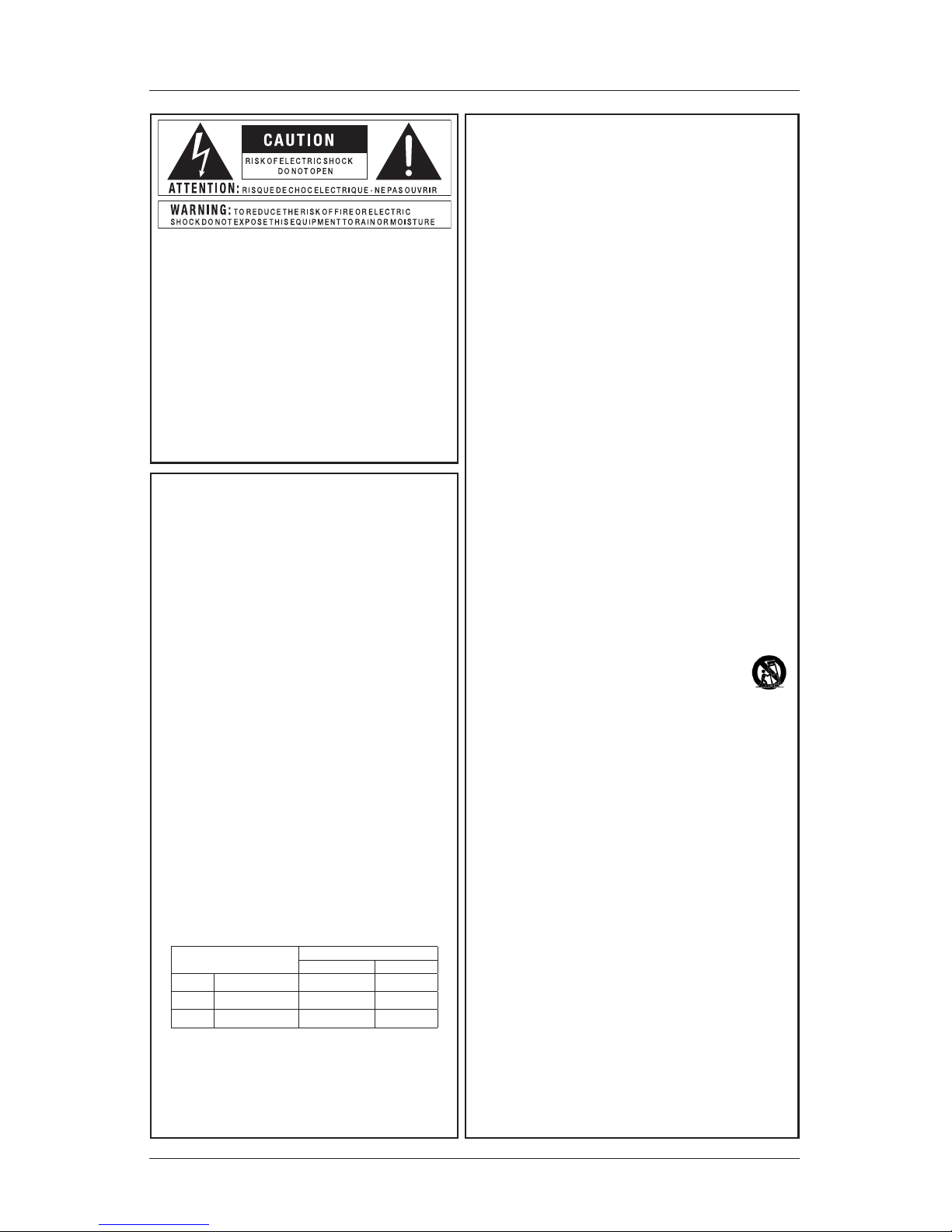
CONDUCTOR
WIRE COLOUR
Normal Alt
L LIVE BROWN BLACK
N NEUTRAL BLUE WHITE
E EARTH GND GREEN/YEL GREEN
WARNING: If the ground is defeated, certain fault
conditions in the unit or in the system to which it
is connected can result in full line voltage between
chassis and earth ground. Severe injury or death can
then result if the chassis and earth ground are touched
simultaneously.
The symbols shown above are internationally accepted
symbols that warn of potential hazards with electrical
products. The lightning flash with arrowpoint in an
equilateral triangle means that there are dangerous
voltages present within the unit. The exclamation point
in an equilateral triangle indicates that it is necessary
for the user to refer to the owner’s manual.
These symbols warn that there are no user serviceable
parts inside the unit. Do not open the unit. Do not attempt to ser vice the unit yourself. Refer all servicing
to qualified personnel. Opening the chassis for any
reason will void the manufacturer’s warranty. Do not
get the unit wet. If liquid is spilled on the unit, shut
it off immediately and take it to a dealer for ser vice.
Disconnect the unit during storms to prevent damage.
Page 4

4
Section 1 - Introductions
ABOUT JBL KX180
KX180 is a professional-grade digital processor designed for karaoke applications
and provides a full set of audio processing for enhancing or fine-tuning music and
voice. KX180 is equipped with three 6.5mm connectors for microphone input,
two groups of RCA connectors and an optical connector for music input, and one
pair of RCA connectors for recording out. It supports storage and recall of up to
10 presets and manual or auto control of Dance or Sing mode.
Echo, Reverb and Effect
KX180 offers five reverb effects: Room, Small Hall, Large Hall, Vocal and Custom.
In Custom effect mode, users are allowed to adjust the following parameters: Early Reflections Volume, Early Reflections Delay, Early Reflections HF Damping,
Later Reflections Volume, Later Reflections Delay, Later Reflections HD Damping, Reverb Space, Reverb Density, Reverb HF Damping, etc.
Among all the parameters, the HF damping will affect the color of the sound, the
higher its coefficient, the more presence of high frequency you will get.
Dance and Sing Mode
KX180 provides two operation modes - Dance and Sing, which can be engaged
automatically or manually. Under Auto control, detection of any active microphone
input will automatically switch the system to the Sing mode from the Dance mode.
The two modes can also be selected manually through its graphic user interface.
Users are allowed to create unique Dance and Sing mode by adjusting parameters of Music, Main Out, Surround, Center and Sub.
Control Methods
KX180 can be fine-tuned through the tailor-designed graphic user interface or
quick set up using the front panel controls. Connection with a VOD system can be
realized through IR.
FEATURES
• Two groups of microphone inputs
• 15-band PEQ and compressor for each Mic Input
• Three levels of Feedback Inhibition for each Mic Input
• Independent control of Echo and Reverberation
• Two pairs of RCA connectors and an Optical connector for Music Input
• 15-band PEQ for Music Input
• Three levels of Excitement for Music Input
• Six output channels: Right, Left, Centre, Sub, Surround Right and Surround
Left.
Page 5

5
• 10-band PEQ for Right and Left Outputs
• 7-band PEQ for Surround and Centre Outputs
• 5-band PEQ for Subwoofer Output
• Compressor provided for each output channel
• Two independent REC channels can be paired into stereo
• Authority control for front panel controls
• Up to 10 presets can be saved
• Dance or Sing mode of each microphone input channel can be switched
manually or automatically
UNPACKING
Please unpack and inspect your processor for any damage that may have
occurred during transit. If damage is found, notify the transportation company
immediately. Only you can initiate a claim for shipping damage. Save the shipping
carton as evidence of damage for the shipper’s inspection.
NOTE: Please save all packing materials for future transportation use. Never ship the unit without the factory pack.
PACKING LIST
• 1 x JBL KX180 Digital Processor
• 1 x Power Cord
• 1 x User Manual
Section 1 - Introductions
Page 6

6
Section 1 - Introductions
FRONT AND REAR PANELS
1 2 3 4 5 6 7 81 2 3 4 5 6 9
7
Front Panel
1. LCD Display: displays the initial settings after boosting or parameters when
any control is used.
2. IR: accepts IR signal sent through an IR remote or transmitter.
3. USB Interface: Type-B USB connector. Connects to a PC for GUI operation.
4. Menu Buttons: includes six parameter buttons (MUSIC, MIC, EFFECT,
SYSTEM, RECALL & SAVE) and two navigation buttons (UP/ESC &
DOWN).
• MUSIC: press to visit or edit Music Input and Output paramters.
• MIC: press to visit or edit parameters of Mic 1, Mic 2 and Mic 3.
• EFFECT: press to visit or edit Effect Input EQ, Echo and Reverb para-
mters.
• SYSTEM: press to visit or edit Signal Source, Initial Preset/Volume,
Limit Volume, Data Save Mode, Music Excite, Microphone Feedback
Inhibition, Keyboard and Authority Control, etc.
• RECALL: press to recall data from a preset.
• SAVE: press to save data to a preset.
• UP/ESC: Short-press will navigate to the previous parameter or escape
to the last screen. Long-press will navigate to the homescreen.
• DOWN: press to navigate to the next parameter.
5. EFFECT / ADJUST/SELECT: this knob can be used for Effect Volume ad-
justment, unlocking the homescreen and parameter editing.
• To adjust Effect Volume: when the LCD shows the homescreen, rotate
the knob to adjust the EFFECT volume.
• To unlock the LCD homescreen: when the LCD is locked, press and
Page 7

7
rotate the knob to enter the 4-digit password and then press to confirm.
• To edit paramters: when the LCD is unlocked and any menu button
(4) is pressed, short-press the knob to enter into the next level menu
or parameter. Short-press the knob to select a parameter. The selected
parameter will flash. Rotate the knob to edit the value.
6. MIC: rotate the knob to adjust microphone volume.
7. MUSIC: rotate the knob to adjust music volume.
1 2 3 4 5 6 7 81 2 3 4 5 6 9
10
Rear Panel
1. MIC 1 & MIC 2: accepts 1/4” (6.35mm) microphone jack plug. A seperate
gain control is provided for each input.
2. MIC 3: accepts 1/4” (6.35mm) microphone jack plug. A gain control is provid-
ed.
3. OPTICAL: accepts digital signal input.
4. BGM: A pair of RCA connectors. Accepts analog input signal.
5. VOD: A pair of RCA connectors. Accepts analog input signal.
6. REC: A pair of RCA connectors. Connects to an audio recorder for karaoke
recording.
7. OUTPUT CHANNELS: include Right, Left, Center, Sub, Surround Right and
Surround Left output. All uses unbalanced XLR connectors to connect to
professional amplifiers or powered speakers.
8. VENTILATION OUTLET: For cooling-air ventilation. Do not block!
9. POWER SWITCH: Press to turn on or off the device.
10. POWER INLET: Accepts AC power using the power cable provided. Power
requirement: ~220VAC 50Hz.
Section 1 - Introductions
Page 8

8
Section 2 - System Connection
SYSTEM CONNECTION
Please refer to the Typical Connection below to set up your audio system.
Analog Connection
Digital Connection
Mic 1&2 Mic 3
PC
VOD Recorder
Amplifier
Right CH
Speaker
Left CH
Speaker
SurrR
Speaker
SurrL
Speaker
Center CH
Speaker
Subwoofer
Amplifier Amplifier
Typical Connection
NOTE:
1. Please ensure all the device are disconnected from power before connection.
2. Please ensure all the volume controls of each device are turned completed down.
3. Please always follow “Last On, First Off” while handling amplifiers or powered speakers.
Page 9

9
Section 3 - Menu Structure
MENU STRUCTURE
MUSIC
Music Input
EQ 01-15
Cutoff Setup: HPF
On / Bypass
PEQ / LS / HS
Q
Gain
Frequency
Frequency
LRCH Output
EQ 01-10
Compressor: LRCH
Delay Setup: Time
Mixer Setup
Mixer Setup: Output
Cutoff Setup: HPF
On / Bypass
PEQ / LS / HS
Q
Gain
Frequency
Threshold
Ratio
Attack
Release
Left Channel Delay
Right Channel Delay
Music Volume + Polarity
Mic Volume + Polarity
Echo Volume + Polarity
Reverb Volume + Polarity
Left Channel Volume
Right Channel Volume
Slope
Frequency
SurrCH Output
EQ 01-07
Compressor: SCH
Delay Setup: Time
Mixer Setup
Mixer Setup: Output
Cutoff Setup: HPF
On / Bypass
PEQ / LS / HS
Q
Gain
Frequency
Threshold
Ratio
Attack
Release
Surround Left Delay
Surround Right Delay
Music Volume + Polarity
Mic Volume + Polarity
Echo Volume + Polarity
Reverb Volume + Polarity
Surround Left Volume
Surround Right Volume
Slope
Frequency
CenCH Output
EQ 01-07
Compressor: CCH
Delay Setup: Time
Mixer Setup
Mixer Setup: Output
Cutoff Setup: HPF
On / Bypass
PEQ / LS / HS
Q
Gain
Frequency
Threshold
Ratio
Attack
Release
Center Channel Delay
Music Volume + Polarity
Mic Volume + Polarity
Echo Volume + Polarity
Reverb Volume + Polarity
Slope
Frequency
Center Channel Volume
SubCH Output
EQ 01-05
Compressor: SubCH
Delay Setup: Time
Mixer Setup
Mixer Setup: Control
Cutoff Setup: HPF
On / Bypass
PEQ / LS / HS
Q
Gain
Frequency
Threshold
Ratio
Attack
Release
Sub Channel Delay
Output Volume
Polarity 0 / 180
Music Volume + Polarity
Mic Volume + Polarity
Slope
Frequency
Mixer Setup: ----
Cutoff Setup: LPF
Slope
Frequency
Music On/Off
Main On/Off
Surround On/Off
Center On/Off
Sub On/Off
Mixer Setup: Sub
Page 10

10
Section 3 - Menu Structure
MIC
Mic Channel 1.2
EQ 01-15
Compressor: Mic 1.2
Mic Setup
On / Bypass
PEQ / LS / HS
Q
Gain
Frequency
Threshold
Ratio
Attack
Release
Mic1.2 Volume
Cutoff Setup: HPF Frequency
Mic Channel 3
EQ 01-15
Compressor: Mic 3
Mic Setup
On / Bypass
PEQ / LS / HS
Q
Gain
Frequency
Threshold
Ratio
Attack
Release
Mic3 Volume
Cutoff Setup: HPF Frequency
EFFECT
Echo Model
Reverb Model
Effect Input EQ
EQ 01-05
Echo Setup
On / Bypass
PEQ / LS / HS
Q
Gain
Frequency
Echo Volume + Polarity
Direct Volume + Polarity
On / Bypass
PEQ / LS / HS
Q
Gain
Frequency
Custom
Room
Small Hall
Large Hall
Voice
Reverb Volume + Polarity
Direct Volume + Polarity
Ref. Volume + Polarity
Late Volume + Polarity
Echo Setup: Time
PreDelay
Delay
Echo Setup: ----
Repeat
Echo Setup: HF Damping
Frequency
Echo Setup: Time
PreDelay R
Delay R
Echo Setup: HPF
Frequency
Echo Setup: LPF
Frequency
Reverb Setup: HPF
Frequency
PreDelay
Reverb Setup: LPF
Reverb Setup: Input
Damping
Reverb Setup: Input
Delay
Reverb Setup: Ref.
Damping
Reverb Setup: Ref.HPF
Delay
Rt_HC
Space
Density
Reverb Setup: Late
Reverb Setup
Reverb Time
Reverb Setup: Late
EQ 01-05
Reverb Model: default
Reverb Setup
EQ 01-05
On / Bypass
PEQ / LS / HS
Q
Gain
Frequency
for “Custom” Reverb Model only
Page 11

11
Section 3 - Menu Structure
SYSTEM
RECALL
Signal Source
Initial Preset Setup
Input Port: BGM/VOD/OPT
Mode: Manual/Auto
Preset: 1 - 10
Initial Volume Setup
Music Volume
Mic Volume
Effect Volume
Limit Volume Setup
Music Volume
Mic Volume
Effect Volume
Data Save Mode
Password
Keyboard Setting
Password
Preset 1-10
Authority Control
Data Recall From
Excite: Off/1/2/3
Music EX Setup
Feedback Inhibition
Mic 1.2 FBC: Off/1/2/3
Mic 3 FBC: Off/1/2/3
SAVE
Preset 1-10
Data Save To
Page 12

12
INFRARED REMOTE CONTROL CODES
IRDA: based on standard IRDA protocal
User code: DB
Volume
Music + 0e Mic + 00 Effect + 0f
Music - 1a Mic - 03 Effect - 01
General Function
Lock 09 Mode Select 0d
Mute 1f Input Select 19
Section 4: Infrared Remote Control Codes
Page 13

13
Section 5: Specifications
SPECIFICATIONS
Audio Inputs
Mic input type 3 x 1/4” unbalanced
Impedance 7.5K Ohms
EIN <-110dBu, 20KHz Bandwidth
Level control –∞ to +0.8dBu
Line input type RCA unbalanced, left & right
Impedance 10K Ohms
Audio Outputs
XLR output type Unbalanced
Level 0dBu Nominal, +14.2dBu Maximum
Impedance 50 Ohms
RCA output type Unbalanced, left & right
Level +17.6dBu Maximum@Mic input,
+13.4dBu Maximum@Music input
Impedance 115 Ohms
Audio Performance
Frequency response 20Hz~20KHz ≤ ±1.0dB
THD+N <0.06% 20Hz to 20KHz
Dynamic range >100dB
A/D conversion 24bit, 48KHz
DSP processor High performance 32-bit/40-bit floating-point pro-
cessor
Infrared Receiver
Carrier frequency 38KHz
Format NEC
Distance Device dependent
Angle Device dependent
Others
Computer connection USB 2.0
AC power supply AC 220V/50Hz
Dimensions (W X D X H) 485 X 205 X 47mm
Net weight 2.8Kg
Gross weight 3.47Kg
To get more information about this product or to download its control software, please go to
www.jblpro.com.
Page 14

14
WARRANTY INFORMATION
The JBL Limited Warranty on KX180 Digital Processor is in effect for one (1)
years from the date of the first consumer purchase.
Who Is Protected By This Warranty?
Your JBL Warranty protects the original owner and all subsequent owners so long
as: A) Your JBL product has been purchased in China Sales Area (This Warranty
does not apply to JBL products purchased elsewhere. Other purchasers should
contact the local JBL distributor for warranty information.); and B) The original
dated bill of sale is presented whenever warranty service is required.
What Does The JBL Warranty Cover?
Except as specified below, your JBL Warranty covers all defects in material and
workmanship. The following are not covered: Damage caused by accident, misuse, abuse, product modification or neglect; damage occurring during shipment;
damage resulting from failure to follow instructions contained in your Instruction
Manual; damage resulting from the performance of repairs by someone not
authorized by JBL; claims based upon any misrepresentations by the seller; any
JBL product on which the serial number has been defaced, modified or removed.
Who Pays For What?
JBL will pay all labor and material expenses for all repairs covered by this warranty. Please be sure to save the original shipping cartons because a charge will
be made if replacement cartons are requested. Payment of shipping charges is
discussed in the next section of this warranty.
How To Obtain Warranty Performance?
If your JBL product ever needs service, please contact your local JBL distributor,
authorized Harman Professional service center or Harman Professional China
Service Center (Hotline: 400 166 7806). You’ll need to present the original bill
of sale to establish the date of purchase. Please do not ship your JBL product
to our Customer Service Center without prior authorization. You are responsible
for transporting your product for repair or arranging for its transportation and for
payment of any initial shipping charges. However, we will pay the return shipping
charges if repairs are covered by the warranty.
Limitation of Implied Warranties
ALL IMPLIED WARRANTIES, INCLUDING WARRANTIES OF MERCHANTABILITY AND FITNESS FOR PARTICULAR PURPOSE, ARE LIMITED IN DURATION
TO THE LENGTH OF THIS WARRANTY.
EXCLUSION OF CERTAIN DAMAGES
JBL’S LIABILITY IS LIMITED TO THE REPAIR OR REPLACEMENT, AT OUR
OPTION, OF ANY DEFECTIVE PRODUCT AND SHALL NOT INCLUDE INCIDENTAL OR CONSEQUENTIAL DAMAGES OF ANY KIND. SOME STATES DO
NOT ALLOW LIMITATIONS ON HOW LONG AN IMPLIED WARRANTY LASTS
AND/OR DO NOT ALLOW THE EXCLUSION OF INCIDENTAL OR CONSEQUENTIAL DAMAGES, SO THE ABOVE LIMITATIONS AND EXCLUSIONS
MAY NOT APPLY TO YOU. THIS WARRANTY GIVES YOU SPECIFIC LEGAL
RIGHTS, AND YOU MAY ALSO HAVE OTHER RIGHTS, WHICH VARY, FROM
STATE TO STATE.
Section 6: Warranty
Page 15

15
SERVICE
PROFESSIONAL CONTACTS
Contact the JBL Professional Distributor in your area.
A complete list of JBL Professional international distributors is available at www.
jblpro.com.
CUSTOMER SERVICE
400 166 7806
Monday - Friday
9:00am - 6:00pm
WEBSITE
www.jblpro.com
PRODUCT REGISTRATION
Register your product online at www.jblpro.com/registration.
Section 7: Service
Page 16

KX180 Digital Processor
User Manual
09/2017
 Loading...