

Page 1

Project K2 S9800
CHAPTER 1
P re f a c e
J B L wishes to thank you for selecting a
P roject K2 S9800loudspeaker system.
It represents the sum total of our research and developmental efforts in
sound reproduction over the last half
c e n t u r y. We have labored to create a
loudspeaker system with no acoustical
or electrical limitations whatsoever.
While the P roject K2 S9800 l o u d-
speaker is itself a new development,
the goal behind it goes right back to
the earliest days of the original James
B. Lansing Sound Company.
But it is your listening pleasure that
ultimately determines how successful
we are in this endeavor. It is solely in
the interest of ensuring a perfect listening experience that we ask you to
faithfully follow the set-up and operation procedures outlined in the P ro j e c t
K2 S9800 Owner’s Refere n c e.
This manual exists for several purposes. As your owner's manual, it contains
all necessary background information
and detailed instructions for setting up
your P roject K2 S9800 l o u d s p e a k e r
system, including unpacking the louds p e a k e r, selecting the correct location,
speaker wire, wiring scheme and
amplification, and connecting it up to
its associated electronics. This information will be found in Chapters 4
through 8. In addition, we have included a detailed description of your
P roject K2 S9800 l o u d s p e a k e r s
(Chapter 3) so that you may become
thoroughly acquainted with its unique
design and technological features.
Although physically and materially
imposing, the set-up procedure of the
P roject K2 loudspeaker system is relatively simple. We strongly urge you to
read this manual thoroughly before you
begin, and consult it frequently
throughout the process. Considerations
must be made in placing the speakers;
their stature makes it imperative that
you become familiar with the entire
set-up process in advance.
Also, we believe that the historical and
technical information included will add
immeasurably to your total enjoyment
of the loudspeaker system. As a louds p e a k e r, P roject K2 S9800is unparal-
leled in the field of sound reproduction.
The story and principles behind it are
an interesting, informative and fitting
precursor to a lifetime of musical
e n j o y m e n t .
1
Page 2

Project K2 S9800
CHAPTER 2
Legacy-the historical development of
the JBL P r o j e c t l o u d s p e a ke r s
Of those few who seek perfection in
sound reproduction, only a handful have
actually achieved it. The price is always
high. It is a rare occurrence indeed
when an individual or group is able to
triumph over the constraints of economic and technological reality just once.
At JBL, this has happened six times. In
each case, its engineers were told to
build the speaker system they had
always wanted to build. W h a t e v e r
resources were required would be made
available. Thus began an ongoing investigation into new frontiers of sound
reproduction, beginning mid-century in
1950 and continuing to the present day.
The products that have resulted from
this venture are now known as the JBL
P ro j e c t loudspeakers. Each represents
the absolute peak of every technological, material and engineering innovation
available at that time, combined into a
single system. They are H a r t s fi e l d ,
Pa ragon, Everest, K2 S9500/7500 and
K2 S5500.The newest is K2 S9800.
Although differing in performance
details and physical attributes, each of
the P ro j e c t loudspeakers has shared a
common objective: to elevate sound
reproduction to levels defined only by
the limitations of existing materials and
t e c h n o l o g y. And despite a spread of
nearly fifty years, all P ro j e c t l o u d s p e a k-
ers have shared many common features-
testimony to their foundation on the
technology and manufacturing techniques upon which JBLwas built.
D e fining the P r o j e c tC o n c e p t
The H a r t s fi e l d began a tradition at JBL
that continues today. First, engineer a
product as close to perfection as possible. When it reaches that level, that is
the time to make it better.
In 1954, the H a r t s fi e l d was significant
not in that it represented n ewt e c h n o l -
o g y, but rather a new level of the alltechnical manufacturing approach pioneered by James B. Lansing some
twenty years before it. Like its P ro j e c t
series successors, it was a high eff i c i e ncy system incorporating compression
driver technology, one combining the
qualities of high output, low distortion,
exceptional stereo imaging and fatiguefree listening. Most important, it was
the first consumer-available listening
system to do so.
In this respect, P roject K2 S9800is at
once the most advanced and sophisticated loudspeaker in the world today a n d a
speaker whose technology is deeply
rooted in over 50 years of tradition.
JBL's president in 1954, W i l l i a m
Thomas, described the Hartsfield as
"...the speaker system we have always
wanted to build ... the finest components ever made available to serious list e n e r s . "
2
Page 3

He went on to describe the process
behind his creation: “Most people who
own and appreciate fine sound reproduction equipment look forward to the
day when they will be able to assemble
a system without limitation in just
exactly the way they think it should be
done. Periodically a manufacturer gets
this same feeling ... The science of
acoustics has provided us with basic
principles-available to all for achieving
precision reproduction. It is only a matter of incorporating these methods into a
system design, and then taking every bit
of trouble necessary to build a system
precisely to the design.”
"It isn't easy, but that's the way it is
d o n e . "
The R a n ge r- Pa rag o n , JBL's second
P ro j e c t system, was the first serious
attempt at a reflecting speaker system,
and broke ground in the new concept of
stereo imaging. Essentially two independent full-range speaker systems
installed in a handsome curved cabinet
nearly 9 feet long, the Pa rag o n ' s e n c l o-
sure was treated as an extension of its
transducers. In essence, the system had
its own "built-in acoustics." In many
respects the Pa rag o nanticipated loud-
speaker developments that would occur
years-and even decades-later.
For nearly 30 years, the Pa rag o n r e -
mained the most acoustically viable
sound system for the home. T o d a y,
along with the H a r t s fi e l d, it is still the
most sought-after speaker in the world.
In 1986, JBL introduced a new P ro j e c t
system that retained the Pa rag o n ' s o v e r-
all sense of musicality while upgrading
its character by incorporating three
decades' worth of continuous development in every facet of its design. Its
name reflected the pinnacle of achievement it represented: P roject Evere s t .
For the first time, the rest of the sound
reproduction chain-and not the loudspeaker or its transducers-would impose
limits on overall system performance.
Like the Pa rag o n and H a r t s fi e l d ,
P roject Evere s t was built around compression driver technology and
addressed a more refined stereo image
than was previously considered technically feasible.
Since P roject Evere s t was introduced,
sound recording and playback technology has undergone a revolution of its
own. With the advent of CD, extremely
demanding recorded signals had
become the rule rather than the exception-the average source material used by
the typical audio enthusiast had become
superior to the best demonstration material of even just a few years ago. In
overall dynamics and transient response,
transducers are once again a potential
weak link in the high-end audio reproduction chain.
It was in this environment that JBL s e t
out to create its fourth and fifth P ro j e c t
loudspeakers, K2 S9500 and K2 S5500.
As with H a r t s fi e l d, the puritan simplicity of a two-way system was considered
the most promising design track.
Advances in transducer design and low
frequency alignment would make the
construction of a two-way system of
3
Page 4

Project K2 S9800
unprecedented physical and acoustical
scale possible. Engineers took the core
components-the low and high frequency
drivers-and optimized them by
redesigning their magnetic structures,
diaphragms and framework for greater
l i n e a r i t y, dynamic capability and transient response.
In the years following the introduction
of the K2 S9500and K2 S5500, sound
reproduction technology underwent
another series of revolutionary changes,
with the introduction of DVD-Vi d e o ,
Dolby Digital, DTS, DVD-Audio, and
Super Audio CD (SACD). Frequency
responses to 50 kHz and 3-digit dynamic range and signal-to-noise ratios have
now become commonplace. In order to
faithfully reproduce such robust sonic
properties, the loudspeaker needed to
u n d e rgo drastic improvements to its
t r a n s d u c e r, network and enclosure techn o l o g i e s .
See Fi g u re 1.
Unlike the earlier P ro j e c t s K2 S9500
and K2 S5500, the new K2 S9800
employed a 3-way design, incorporating
an Ultra High Frequency (UHF) compression driver and horn to reproduce
high frequencies up to 50 kHz. With the
UHF handling the high frequencies, the
High Frequency (HF) transducer could
then be upgraded to a new design using
a 3 inch diaphragm for better reproduction of lower frequencies and better
blend with the woofer than the older
g e n e r a t i o n s ’2-inch diaphragm. Both
compression drivers utilized newly
developed Beryllium diaphragms to
provide the lowest distortion and flattest
frequency response possible.
In order to recreate the extremely high
dynamic range provided by today’s
audio sources, a brand new low frequency transducer was developed from
ground up, utilizing an Alnico magnet,
4-inch edge wound Voice Coil, and an
Aquaplas™-coated 15 inch cone with
EPDM rubber surround. Extensive
c o m p u t e r-aided engineering and design
e ffort made to develop the optimized
port tuning employed in P roject K2
S 9 8 0 0 has resulted in a significant
advance in the concept of state-of-theart bass reproduction. This proprietary
alignment method offers the best damping characteristics and provides
extremely fast alignment, eliminating
the typical "bass-reflex" sound of a ported system.
All three transducers were built using
the most advanced materials and precision manufacturing techniques refined
from renowned JBL professional sound
s y s t e m s .
High power handling capability results
in no limitations on the types of source
material. P roject K2 S9800 has very
high input sensitivity; even a relatively
small high-end amplifier can provide
full dynamic range without compress i o n .
Despite its power and sophistication,
P roject K2 S9800 is a marriage of tradition and technology. It reflects the
design, engineering and manufacturing
expertise derived and refined through
nearly six decades of experience that are
the exclusive province of one loudspeaker builder: JBL.
4
Page 5

Figure 1
5
Page 6

Project K2 S9800
CHAPTER 3
The Project K2 S9800 l o u d s p e a ker: a
triumph in acoustics and technology
The following sections describe the
primary features and components of
the P roject K2 loudspeaker system.
The enclosure of the K2 S9800 is spe-
cially designed to transfer unwanted
mechanical energy away from any
acoustically-active surfaces, virtually
eliminating coloration.
Its massive base, along with its specially designed stainless steel modular
feet, couple directly to the floor, and
the system literally becomes a structural part of its environment. Any vibration is transmitted harmlessly down the
channel provided by the ring/disc axes
and into the floor. Both horns, the UHF
housing and the enclosure top are constructed from JBL’s exclusive
SonoGlass™, an extremely dense and
mechanically inert material, in order to
maintain a smooth energy transmission
p a t h .
See Fi g u re 1
The P roject K2 S9800 t r a n s d u c e r /
enclosure arrangement represents the
best possible balance of the various
tuning options and avoids the mid-bass
response build-up found in other vented
systems. Response works with, rather
than against, the effects of "room loadi n g . "
The unique design of the P roject K2
system is the platform for its equally
unique acoustical attributes.
The HF (high frequency) driver is
located at the exact ear level of the list e n e r. The UHF (ultra high frequency)
driver is slightly tilted down so that its
information is also directly reaching the
l i s t e n e r’s ear. Thanks to the large HF
t r a n s d u c e r, the 15 inch woofer can be
crossed over at a frequency low enough
to eliminate any audible effects of its
exact location and proximity.
Full image coherency is maintained,
resulting in an acoustically stable pinpointed stereo image. All the sound
seems to come from the HF horn in the
c e n t e r. Music imaging is more realistic
since the sound appears to emanate
from one point and not from multiple
points at different times.
P roject K2 is a fixed angle system
without regard to frequency. Careful
horn design enables the loudspeaker to
strictly adhere to a 60° horizontal/30°
vertical coverage pattern. This Controlled Coverage arrangement precisely
defines the optimum listening area and
minimizes room effects. At the same
time, it provides a generous "sweet
spot" for more comfortable critical listening sessions.
The 1500AL Low Frequency Drive r
See Fi g u re 3
In order to achieve the lowest possible
distortion and compression along with
the high linear excursion necessary, the
1 5 0 0 A L is equipped with an A l n i c o
magnet. As with earlier P roject K2 l o w
frequency drivers, it utilizes forced air
cooling. The entire magnetic structure
is completely enclosed within a die-
6
Page 7

Figure 2
Figure 3
7
Page 8

Project K2 S9800
cast aluminum alloy frame. This provides accurate, rigid support for the
motor and cone mounting points, as
well as doubling as a massive heat sink
by providing a huge surface area for
heat dissipation.
Instead of the conventional single pole
piece thermal vent, the 1500AL h a s
three separate gap cooling ducts which
more effectively cool the voice coil
and reduce the likelihood of hot spots.
By reducing the operating temperature
of the voice coil, power compression is
significantly reduced, which enables
the low frequency driver to operate in
a more linear fashion over a wider
sound pressure level (SPL) range.
The voice coil itself is constructed
from edge wound Aluminum wire on a
massive 4-inch in diameter Fiberg l a s s
f o r m e r. This configuration provides for
further cooling ability in conjunction
with the motor design.
The Aquaplas™-coated cone along
with EPDM Rubber Surround provides
excellent damping and transient
response characteristics.
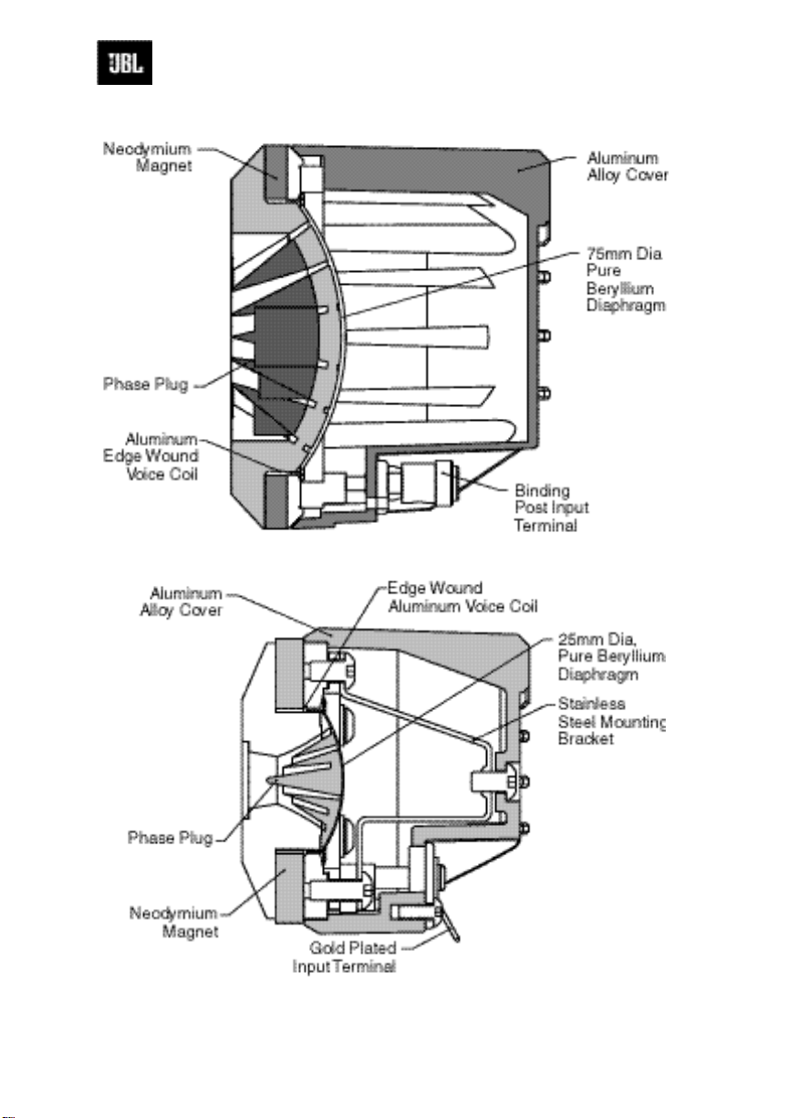
435Be Beryllium diaphragm/
Neodymium magnet High Fre q u e n c y
C o m p ression Drive r
See Fi g u re 4
The 435Be neodymium high frequency
compression driver is based on the professional JBL2435 device. It incorporates a rare-earth neodymium magnet
structure, designed by extensive computer modeling, including finite element analysis, which combines the
attributes of ef f i c i e n c y, strength, low
mass and compact size. This motor
structure is coupled with a 3-inch
Beryllium diaphragm. Beryllium provides improved low distortion and flat
frequency response over Aluminum or
Titanium, thanks to its higher stiff n e s s to-mass ratio. This diaphragm is dusted
with Aquaplas™, JBL's proven acoustical damping material, to reduce
breakup and smooth out natural
response irregularities.
High temperature materials and adhesives allow the driver to handle extremely high power levels over extended periods of time. The SonoGlass™
horn is acoustically inert and precisionmolded to exacting tolerances. It incorporates a unique tubular energy transmission system.
045Be Beryllium diaphragm/
Neodymium magnet Ultra-High
F requency Compression Driver
See Fi g u re 5
The 045Be utilizes the same principles
and materials as the 435Be, in a smaller
footprint so that a frequency response
up to 50 kHz can be achieved. T h i s
transducer was developed specifically
for the K2 S9800.
I n t e rnal Cro s s over Netwo r k
Each loudspeaker unit has three internal
dividing networks, one for each transd u c e r. Ultra high frequency, high frequency and low frequency signal paths
are completely independent to reduce
any possibility of crosstalk or interference from the relatively large capacitors and inductors.
8
Page 9
435Be
Figure 4
045Be
Figure 5
9
Page 10

Project K2 S9800
The low frequency section interfaces
with the external main control panel for
input connections and switch functions.
They also employ massive air core
inductors for best possible sonic characteristics and lowest possible colo r a t i o n .
All internal connections are of proprietary Monster Cable®, and all critical
connections are gold plated for long
life. Capacitors are ultra high grade
mylar for extremely low loss, and are
bypassed with polypropylene for
improved transient behavior. Network
plates and the port bezels are metal to
eliminate vibration and help conduct
unwanted heat away from the network.
All switches and components are of the
highest quality for long life and
reduced distortion of all types.
The network also utilizes JBL’s proprietary Charge-Coupled topology, which
e ffectively "charges" the network at all
times so that all components are constantly on and do not have to generate
distortion while switching between on
and off stages. This is accomplished by
a battery that biases the components in
the network.
The network also facilitates bi-amping
and bi-wiring as necessary, using configuration switches and twisted pair
j u m p e r s .
The HF level control allows fine tuning
of the high frequency output level to
the acoustics of the listening space as
well as to the listener’s liking.
ADamping (Q) Adjustment knob is
also provided to fine tune the interaction of the low frequency section of the
K2 S9800 with the power amplifier in
u s e .
E x t e rnal Connections
The input connectors provide for both
bi-amplification and bi-wiring, which
are explained in detail later in this
g u i d e .
E n c l o s u re s
The enclosure design of the P roject K2
S 9 8 0 0 minimizes coloration by dramat-
ically reducing panel radiation. It is
constructed from 25 mm (1 inch) thick
MDF and SonoGlass™ panels.
The enclosure's unusual thickness,
along with the SonoGlass™ panels,
add up to the lowest vibration, most
acoustically inert loudspeaker enclosure
presently possible to construct.
Enclosures are finished with a highgloss polyurethane lacquer.
Base and Fe e t
P ro j e c t K2 S9800 terminates in a massive base consisting of 3 layers of different panels along with specially
designed stainless steel spiked feet.
All unwanted mechanical vibration is
channeled down via the point-to-point
e n e rgy transmission system and dissipated into the base, which is massive
enough to couple acoustically to the
floor and therefore the dwelling subs t r u c t u r e .
10
Page 11

CHAPTER 4
Unpacking the Project K2 S9800
S y s t e m
All components of the P roject K2 s y s-
tem have been very carefully packed
for maximum protection against damage.
As with any superior audio product, it
is advisable to keep the original packing materials in case it is necessary to
transport the P roject K2 S9800 s y s t e m .
Because of the bulk and weight of this
l o u d s p e a k e r, at least two people are
required to unpack it in the following
manner: open the box, push back the
flaps, and then slowly and carefully roll
the loudspeaker and its contents over
onto a well protected surface such as a
thick carpet; lift off the box.
Two choices of feet, spiked and rounded are provided. Please s e e Fi g u re 6,
and thread either type of foot onto the
bottom of the K2 S9800 in four loca-
t i o n s .
Four metal coasters are also provided.
These are to be placed between the foot
and the floor should further protection
of the floor coverings be required.
Project K2 S9800
11
Page 12

Figure 6
12
Page 13

Project K2 S9800
CHAPTER 5
Selecting Cable
Speaker wire and interconnecting
cables are an important component in
any audio system. With a system such
as the P roject K2 S9800, they assume a
new level of criticality.
The P roject K2 S9800 l o u d s p e a k e r s
are internally wired with proprietary
high quality copper Monster Cable®,
specially designed for JBL. The same
care that was given to the selection of
internal system wiring should be
a fforded to the selection and application of the cables that will connect
P roject K2 S9800loudspeakers to
other system components.
It is advisable to use high quality wire,
such as Monster Cable®, and to select
the highest grade wire available from
the manufacturer. Many manufacturers
produce audiophile cables worth considering for P roject K2 S9800. As with
all electronics and associated components, however, every manufacturer
o ffers products of varying quality to
suit a range of budgets and applicat i o n s .
We recommend using an audiophile
quality speaker wire of not less than 16
gauge for connections up to 5 meters
(15 feet) as a minimum r e q u i r e m e n t .
If your connections will be longer,
heavier gauge wire is recommended.
P roject K2 specialist dealers have the
experience and knowledge to recommend suitable speaker wire to best
complement a particular system.
The amount of speaker wire required
will depend on the distance between
the loudspeakers and amplifier(s), how
many amplifiers will be used, and the
method you select for connecting the
amplifier(s) and loudspeakers (passive,
bi-wire, or bi-amp; see Chapter 8). For
maximum signal purity, it is advisable
to locate the amplifier(s) as close as
possible to the loudspeakers, even if
this means that a longer distance will
be needed between the amplifier(s) and
p r e a m p l i f i e r.
Both the left and right speaker/amplifier connections should be the same
length. If the distance between one
speaker and the amplifier(s) is greater
than the other speaker and amplifier(s),
use the longer length for both connect i o n s .
For bi-wire connections, the same type
of wires may be used for both low frequency and high frequency sections to
reduce wire effects (resistance, inductance, etc.) and to avoid intermodulation of low and high frequencies in the
wires. Specialized wires for low frequency and high frequency sections
may yield excellent results. W h a t e v e r
wires are used, be sure that the low frequency wires are as short as possible
and the left and right wires for each
section are the same length.
13
Page 14

Project K2 S9800
CHAPTER 6
A m p l i fier Recommendations
No single type of amplifier is specified
for use with the P roject K2 S9800 s y s-
tem. The speakers are highly eff i c i e n t
and will operate adequately with an
amplifier or receiver of 70-100 watts.
H o w e v e r, the transient response and
audio definition of a high-end system
such as P roject K2 S9800will pick up
all inefficiencies and distortion in an
amplifier system. For full-range operation, the P roject K2 S9800 s y s t e m
should not be used with an
amplifier/receiver of less than 100
watts. Amplifiers/receivers of 100-500
watts will ensure optimum system perf o r m a n c e .
There is no effective limit to the power
handling capabilities of the P roject K2
S9800 loudspeakers when driven by
consumer audio amplifiers. No damage
will occur when used with high powered components. Source impedance is
an important criteria in selecting an
appropriate unit; the selected amplifier(s) should have a very high current
capacity and must be capable of driving
a low-impedance load.
For bi-wiring or bi-amplification applications, four identical amplifiers or two
dual-channel units may be used,
although specialized low frequency and
high frequency amplifiers offer clear
advantages. (If four amplifier channels
are used, the high frequency amplifier
may be up to 6 dB less powerful than
the low frequency amplifier. Due to the
power versus frequency distribution of
the music, the low frequency section
requires approximately four times the
power of the high frequency section.)
P roject K2 S9800 specialist dealers can
recommend amplification to best suit
individual needs. In all cases, the left
and right amplifiers for each section
must be identical. Make sure that the
input sensitivity of the two amplifiers is
equal or that input level controls are
provided to maintain the proper low to
mid/high balance. If two identical
stereo amplifiers are chosen, each
amplifier may be located near a loudspeaker and drive low frequency and
high frequency sections through short
wire runs.
14
Page 15

Project K2 S9800
CHAPTER 7
Placement and Set-up
C o n s i d e r a t i o n s
The P roject K2 S9800 l o u d s p e a k e r
system is designed to be less aff e c t e d
by room acoustics than conventional
imaging systems. However, it is very
sensitive to overall symmetry, proximity to walls, ceilings and corners.
I d e a l l y, any listening room should contain a combination of live surfaces
(e.g., walls and windows) and
absorbent surfaces (e.g., drapes, carpets, upholstery). If the distance
between floor to ceiling is low, it is
preferable that one surface has an
absorbent covering. With P roject K2
S 9 8 0 0, it is most important to be able
to accommodate the optimum listening
area that is defined by the 60° horizontal/30° vertical coverage pattern of the
h o r n .
The listener should be centered in front
of the speakers and furniture should be
of an appropriate height so that when
the listener is sitting, the ear level is on
a vertical plane with the horn (approximately 110 cm/43 in) as illustrated in
Fi g u re 2.
C AUTION: Project K2 S9800 is a mas-
sive system comprised of materials chosen for their density, with its weight
concentrated in a relatively narrow area.
Verify the integrity of the floor surface
before placing and setting up the speakers. S e e Floor Require m e n t s .
If possible, the distance between the
speakers should be the same as the distance between each speaker and the lis-
tening area. Angle the speaker in
toward the listener so that when seated,
the listener could look straight into the
center of the speaker ( Fi g u re 7). As the
distance increases between the speakers, increase the inward angle of the
s p e a k e r.
The imaging qualities enable the
speakers to be placed relatively far
apart from each other. In addition, the
low frequency alignment feature
enables placing the speakers near or
even in a corner without producing an
over abundance of bass. This corner
placement ability allows optimum performance even in small rooms.
The P roject K2 S9800 system can
operate fairly closely to the wall.
Allow enough clearance between the
back of each speaker and the wall to
allow making the connections on the
back of the speaker (approximately 45
cm/18 in). Remember that these speakers weigh close to 90 kg (198 lbs) each
and cannot be easily moved.
Floor Require m e n t s
The floor in the location selected for
setting up the P roject K2 S9800 s p e a k-
ers must be capable of supporting a
load of 90 kg (198 lbs). Because of the
coupling effect of the stainless steel
feet, a flat, hard surface such as wood
or linoleum is preferable. However, the
design of the loudspeaker's coupling
system, along with the speaker's
extreme weight, should result in excellent perfomance on any surface, even
on carpets.
15
Page 16

To prevent indentations on wood or
linoleum floors caused by the weight
of the loudspeaker, always utilize the
enclosed coasters. Do not set up the
P roject K2 S9800system directly on a
ceramic tile floor; the concentrated
weight might cause the tiles to crack.
16
Page 17

Project K2 S9800
Figure 7
17
Page 18

Project K2 S9800
CHAPTER 8
Project K2 S9800 Switch Operations
See Fi g u re 8.
The K2 S9800 has 3 switches mounted
on the network panel on the rear of the
enclosure. The switches are covered by
an access plate which is easily removed
by unscrewing the 2 knurled mounting
screws. The access panel has holes in it
which line up with two of the adjustment switches. This allows for trimming of the system response without
removing the panel. Panel removal is
necessary to operate the Bi-Amp switch
and for installation/changing of the batt e r y.
The Bi-Amp switch (center) should be
left in the Normal position except when
bi-amplification with an external electronic crossover is to be employed. T h e
necessary crossover slopes for the K 2
S 9 8 0 0 are very specific and Bi-Amping
the system should only be done using
factory approved electronics.
The LF Damping switch (left most)
serves two functions. Operating the
switch changes the "Q" of the LF
crossover as it transitions into the High
Frequency driver. High damping (H)
yields the flattest woofer response. T h i s
is the most clockwise position.
Medium damping (M) allows the
woofer response to rise by about 0.5 dB
over the range of 200 Hz to 600 Hz for
a somewhat "warmer" sound.
Low damping (L) causes the woofer
response to rise by an additional 0.5 dB
over the same range. The Damping
switch also controls the interaction
between the woofer and the driving
amplifier at low frequencies (approximately 30 Hz to 80 Hz) by changing
the reactive load presented to the
a m p l i f i e r. The High setting gives the
tightest damping with Medium and
Low each giving slightly less firmness.
The HF Level switch (right most)
adjusts the High Frequency level over
the range of approximately 1000 Hz to
10 kHz. Position "3" (most clockwise)
gives the highest HF output and measures the most level. Position "2"
reduces the HF level by 0.75 dB and
position "1" reduces the HF level by an
additional 0.75 dB.
Although the range of these controls is
rather small, each of them operate over
a reasonably wide frequency range and
thus have a noticeable affect on the
overall tonal balance of the system. It is
recommended that the system first be
played with the switches in the full
clockwise position ("H" & "3"). T h e s e
settings give the most uniform measurements in a controlled environment.
Of course, we are interested in producing the most pleasing sound in your
environment with your choice of program material. It is, therefore, recommended that each of the controls be
tested in their various settings on a variety of program material. Once you
become familiar with their individual
c h a r a c t e r, you should have no diff i c u l t y
determining the settings which produce
the most pleasing, natural sound in
your room with your equipment.
18
Page 19

19
Figure 8
Page 20

Project K2 S9800
Jumper Connections
The K2 S9800 is shipped with Tw i s t e d
Pair Wire Jumpers installed between its
low frequency and high frequency terminals. Please s e e Fi g u re 9. To prepare
the K2 S9800 for bi-wire or bi-amp
operation, these jumpers must be
removed by completely unscrewing
each binding post, removing the
jumpers, and replacing the binding
posts. Wires can then be connected to
each set of terminals (s e e Fi g u re 10) .
A m p l i fier Connections
I m p o r t a n t : Turn all amplifiers off
before connecting or disconnecting
P roject K2 S9800l o u d s p e a k e r s .
Making connections while an amplifier
is operating could seriously damage
the loudspeaker system and void the
w a r r a n t y. All amplifiers must also be
turned off before connecting or disconnecting cables at the amplifier or preamplifier inputs.
All connections between the amplifier(s) and the P roject K2 S9800 1oud-
speaker system are made at the terminals located on the back of the enclosure (Fi g u re 9 and 10). The left-hand
terminals (black stripe) are negative,
and the right-hand terminals (red
stripe) are positive. These correspond
to the negative and positive conductors
in the speaker wire. Each speaker wire
contains two conductors, one of which
will have a stripe, color markings, or a
r i d g e .
Assign one of the two conductors as
the negative conductor and the other as
the positive conductor. Use these same
designations for all system wiring.
Always connect the conductors of the
speaker wire appropriately to the corresponding negative and positive terminals on all system components. T h i s
will ensure that all components will
work together ("in phase"). Connecting
the speakers out of phase will not damage them but will result in reduced low
frequency output and impaired stereo
e ff e c t .
Speaker wires may be fastened to the
terminals by several methods. T h e
most positive connection is made by
directly connecting clean, bare connectors (exposed by stripping the ends of
the wire) to the terminal posts.
For this type of connection, loosen the
knobs on the terminals and insert the
exposed (bare) ends of each speaker
wire into the hole exposed on the terminal shaft ( + to +, – to – ) (s e e
Fi g u re 11). Retighten the knob on each
terminal so that a snug positive connection is achieved. Do not apply
excessive force and do not overtighten.
To avoid a short circuit, trim off any
excess wire that is not in contact with
the binding post contact surfaces.
20
Page 21

21
Figure 9
Page 22

Project K2 S9800
22
Figure 10
Page 23

A
B
C
D
Figure 11
23
Page 24

Project K2 S9800
P roject K2 S9800terminals are also
designed to accept spade or bananatype connectors which are fastened to
the ends of the wires and, in turn, are
attached to the terminal posts.
As mentioned earlier, the P roject K2
S 9 8 0 0 speakers may be connected to
the amplifier(s) by one of three methods: passive, bi-wire and bi-amp. Each
method, described below, has its own
advantages, and the P roject K2l o u d-
speaker system will deliver superb performance with all methods.
J B L recommends the bi-amp method
(in conjunction with the JBL D X l
crossover network) for maximum performance. If this method is not desired,
the bi-wire connecting method is
preferable to the passive method, if
possible. Consult with the P roject K2
S 9 8 0 0 specialist dealer if assistance is
required in choosing the best method
for a particular system.
Each speaker is shipped with external
shorting straps (twisted pair wire
jumpers) in place, (see Fi g u re 9) con-
necting the upper and lower terminal
posts on the left and right sides. T h e s e
straps must remain in place for passive
connections but must be removed for
all bi-wire and bi-amp connections.
Caution: If the amplifiers are connected to the P roject K2 S9800 l o u d s p e a k-
ers in the bi-wire or bi-amp mode with
the shorting straps still on, the amplifier outputs will he shorted which could
result in costly amplifier damage when
power is switched on.
Pa s s ive Connecting Method
The passive method requires one amplifier and one set of wires. Connections are made to the upper terminals
(one black, one red). Do not remove
the shorting straps. Loosen the upper
terminal caps. Connect the positive
conductor to the right (red) terminal
and the negative conductor to the left
(black) terminal (see Fi g u re 11).
Refasten the terminal caps.
B i - Wi re Connecting Method
The bi-wire connection method requires one amplifier and two sets of
speaker wires. By removing the shorting straps, connections may be made to
the individual network sections using
four conductors, one for each of the
four terminals. (see Fi g u res 9 & 10)
Bi-Amp Connecting Method
The optimal method of powering the
P roject K2 system is with two amplifiers, one for the low frequency and
one for the high frequency unit, and a
crossover network. Since each amplifier drives only one speaker, this method
allows the user to select amplifiers
with the desired sonic character for
low and high frequencies (see Fi g u re s
9 & 10).
24
Page 25

Four identical amplifiers (or two dual
channel units) may be used, although
specialized low and high frequency
amplifiers offer clear advantages. T h e
P roject K2 specialist dealer can recommend the amplification that will best
suit individual needs.
In all cases, the left and right amplifiers for each section must be identical.
Make sure that the input sensitivity of
the amplifier for each section is equal,
or that input level controls are provided
to maintain the proper low-to-mid/high
balance. If two identical stereo amplifiers are used, one may he located near
each loudspeaker and drive low and
high frequency sections through short
wire runs.
NOTE: Input polarity must be the
same for both the low and high frequency sections. Some amplifiers
invert polarity. If the polarity is
reversed to one section, a discontinuity
in response will be apparent in the
crossover region. If a problem is suspected, reverse the polarity to either
low or high frequency sections of both
loudspeakers. Amplifier polarity markings may not ensure correct polarity
c o n n e c t i o n s .
The Woofer Grille:
The grilles on the P roject K2 S9800
loudspeaker system have been
designed for maximum acoustical
t r a n s p a r e n c y. For the most critical listening, however, JBLsuggests removing the grilles. The grilles are connected by four pins inserted into four holes
on the face of the cabinet.
To remove each grille, hold the grille
edges with your fingers and gently pull
the grille away. Do not use any tools to
pry the grille off; this will damage the
finish of the cabinet. To replace the
grille, position the mounting pins over
the holes and gently press until the
grille meets the enclosure.
Project K2 Final Checklist
- Connect and plug in all other system
e l e c t r o n i c s .
- Check all connections. If bi-amping
or bi-wiring, make sure both shorting
straps are removed.
- Make sure three controls on the
crossover panel are correctly set.
The system is now ready for use. T h e
P roject K2 S9800 speaker system is
fully functional as soon as it is set up.
There are no restrictions on the amount
of amplification that may he applied.
There may be some subtle tonal
changes in bass output over the first
week to 10 days of operation. T h e s e
are caused as the movement of the low
frequency drivers becomes more fluid
and the parts settle in. This process is
completely normal and natural with
transducers of this caliber.
25
Page 26

CHAPTER 9
Project K2 S9800 Care and
Maintenance
The Project K2 S9800 loudspeaker
system is finished in a lacquer and
requires no maintenance other than an
occasional dusting with a soft, dry,
lint-free cotton cloth.
The horns may also be wiped with a
soft cloth. Treat the lacquered surface
very carefully to avoid scratching the
finish. To remove fingerprints and
smudges, apply a small amount of
ammonia-free window cleaner to the
cloth and gently clean the surface.
Never use any abrasive cleaners or
chemicals to clean the enclosure. if
the enclosure becomes perceptibly
scratched or otherwise damaged, consult a qualified furniture repair shop.
All wiring connections should be inspected and cleaned or remade periodically. The frequency of maintenance depends on the metals involved
in the connections, atmospheric conditions, and other factors. Consult the
Project K2 specialist dealer for spe-
cific recommendations.
Project K2 S9800
26
Page 27

CHAPTER 10
Troubleshooting and Service Guide
Project K2 S9800 loudspeakers are
designed to provide years of troublefree service. No maintenance is
required.
If a problem occurs, make sure that
all connections are properly made and
clean. If a problem exists in one loudspeaker, reverse the speaker wires to
the left and right system. If the problem remains in the same speaker, then
the fault is in the loudspeaker. In this
event, consult the Project K2 S9800
specialist dealer for assistance. If the
problem appears in the opposite
speaker, the cause is in another component or cable.
Project K2 S9800
27
Page 28

CHAPTER 11
The Project K2 S9800 Register
In purchasing a Project K2 S9800
loudspeaker system, one has joined a
privileged group of music lovers who
have sought, and finally found, a system that will reproduce sound to a
level of perfection of which no other
system in the world is capable.
JBL has established the Project K2
S9800 Register so that we can maintain an ongoing dialog with all
Project K2 S9800 system owners.
Through periodic letters and mailings, we will be able to communicate information of interest to Project
K2 S9800 owners, including news of
technological advancements, new
products, and special promotions. We
look forward to sharing these items
with those who have chosen to invest
in a Project K2 S9800 loudspeaker
system.
Project K2 S9800
28
Page 29

CHAPTER 12
Project K2 S9800 Specifications
Project K2 S9800
Power Handling:
Frequency Response:
Low Frequency Extension:
Sensitivity:
Nominal Impedance:
Crossover Frequency:
Low Frequency Driver:
High Frequency Driver:
Ultra-High Frequency Driver
Dimensions:
400W (RMS)
45Hz - 50kHz
35Hz (-10dB)
94 dB (2.83V/1m)
8 ohms
800Hz, 10kHz
380mm (15”) Pulp-Cone Woofer
(1500AL)
75mm (3”) Pure Beryllium
Compression Driver (435Be) +
38mm (1.5”) - throat Bi-radial Horn
25mm (1”) Pure Beryllium
Compression Driver (045Be) +
8.9mm (0.35”) - throat Bi-radial Horn
508mm (w) x 1,295mm (h) x 375mm (d)
Weight:
90kg (198.4 lbs) per unit
29
Page 30

Project K2 S9800
JBL and Harman International
JBL is part of the Harman
International audio companies, a
group with a common purpose: combining technology with a love of
music to manufacture audio products
that provide new levels of satisfaction, performance and value.
To promote diversity and creativity,
JBL operates independently in
research and development. When it
comes to translating the results of
these efforts into actual consumer and
professional products, JBL draws on
the full combined strength of the
Harman companies, which includes
one of the world's most advanced
manufacturing facilities. The result of
this teamwork is that JBL's renowned
excellence in engineering is successfully carried through to each individual product, regardless of its application or price range.
As new audio concepts and technologies are pioneered, the partnership of
JBL and Harman International guarantees that consumer and professional
audio users everywhere will be able
to enjoy their full range of benefits.
JBL continually engages in research
related to product development and
improvement. Because of this, new
materials, production methods and
design refinements will be introduced
into existing products without notice.
For this reason, any current JBL
product may differ in some respect
from its published description, but
will always equal or exceed the original design specifications unless otherwise stated.
©Copyright 2001 JBL Incorporated
JBL Incorporated
8500 Balboa Boulevard
Northridge, CA 91329
USA
JBLis a registered trademark of JBL, Inc.
Monster Cable is a registered trademark of
Monster Cable Products, Inc.
Aquaplas and SonoGlass are registered trade-
marks of JBL, Inc.
Part No. 338316-001
30
 Loading...