

Page 1
Technical Manual
K2 S9800
ACOUSTIC & ELECTRICAL SPECIFICATIONS:
• Nominal Impedance 8Ω
• Max Amp Power 400 watts*
•Frequency Response 45Hz – 50kHz (–6dB)
• Sensitivity 94dB (2.83 volts @ 1 meter)
• Crossover Frequencies 800Hz, 10kHz
SYSTEM COMPONENTS:
• Cabinet K2S9800
(Not for Sale)
•Grille 337854-001
• Ultra-High Frequency 1" (25.4mm) 045Be
Transducer Beryllium (336318-001)
DC Resistance 3.1 ohms ±3%
•High-Frequency Transducer 3" (76.2mm) 435Be
Beryllium (337361-001)
DC Resistance 3.6 ohms ±10%
•Low-Frequency Transducer 15" (381mm) 1500AL
Alnico (336308-001)
DC Resistance 5.3 ohms ±10%
• Crossover Network 337978-001
AURAL SWEEP TEST SPECIFICATIONS:
• System Aural Sweep Test 6.0V Input 40Hz to 50kHz
• L.F. Aural Sweep Test 20.0V Input 20Hz to 600Hz
• H.F. Aural Sweep Test 2.0V Input 500Hz to 10kHz
•U.H.F.Aural Sweep Test 1.00V Input 7kHz to 50kHz
PHYSICAL SPECIFICATIONS:
• Enclosure dimensions 51" x 20" x 14.75"
Plus spiked feet
(1295mm x 508mm x 375mm)
•Weight 198 lb./90kg Each
WARRANTY:
• Refer to Warranty Statement packed with each product
* The maximum recommended amplifier power rating will ensure
proper system headroom to allow for occasional peaks.We do
not recommend sustained operation at these maximum power
levels.
JBL Consumer Products, 250 Crossways Park Drive, Woodbury, New York 11797
1Rev 1 2/2002
K2 S9800
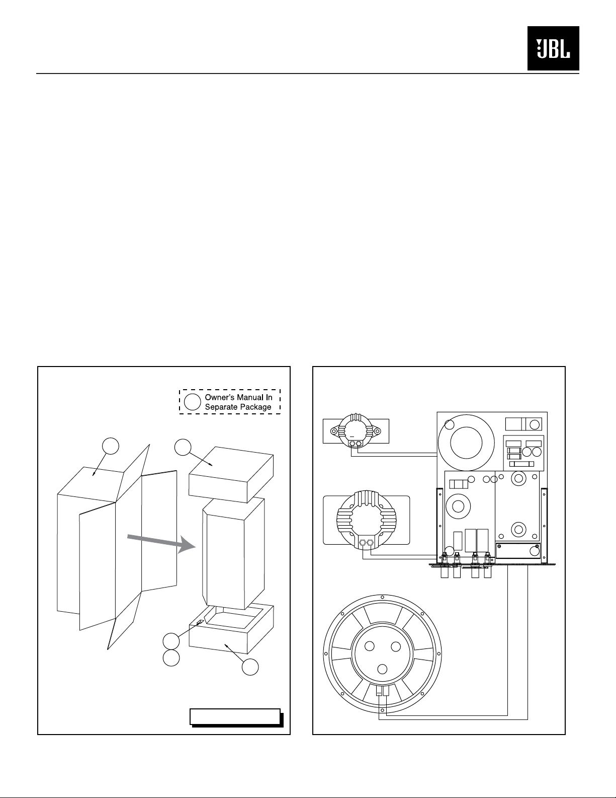
PACKAGING
42
46
47
43
45
44
K2 S9800 WIRING DIAGRAM
UHF
336318-001
HF
337361-001
LF
336308-001
+
ORN/BLK
BLK
YEL/BLK
ORN
RED
YEL
CROSSOVER NETWORK
337978-001
+
Legend on Page 4
GRN
GRN/BLK
Page 2
L.F.
+
–
U.H.F.
H.F./U.H.F.
INPUT
L.F.
INPUT
+
–
H.F.
.205
.110
–IN
+IN
–IN
+IN
R1
150ohm
5W
R5A
60ohm
5W
RED ORN
ORN/BLK
BLK
R5B
60ohm
5W
R6A
60ohm
5W
R6B
60ohm
5W
R8
9.1ohm
5W
R9
6.8ohm
5W
R10
12ohm
5W
R1
33ohm
5W
R1
1.5ohm
1W
R7
1.8ohm
5W
R2
33ohm
5W
R3
130ohm
1W
R4
62ohm
1W
BI-AMP
S1C
BI-AMP
S4A
HF LEVEL
2
1
3
NORMAL
C3CC3A
C3B
C3A C4AC2AC1A
C3B C4BC2BC1B
C5BC5A
C6BC6A
C7BC7A
C8BC8A
C9BC9A
C10BC10A
C11BC11A
C12BC12A
YEL
YEL/BLK
C1A C2A
C1B C2B
9V
9V
9V
9V
9V
R102
2.2Mohm
1/4W
R103
2.2Mohm
1/4W
9V
R104
2.2Mohm
1/4W
9V
R105
2.2Mohm
1/4W
9V
R106
2.2Mohm
1/4W
R101
2.2Mohm
1/4W
R101
2.2Mohm
1/4W
R102
2.2Mohm
1/4W
L2
.2mH
L6
.6mH
L1
.25mH
L1
.03mH
L2
.15mH
L4
1.0mH
L3
2.0mH
L5
1.0mH
R101
2.2Mohm
1/4W
9V
HM L
S2
LF DAMPING
L1
4.5mH
NORMAL
NORMAL
BI-AMP
S1A, B
BI-AMP
RED
GRN
GRN/BLK
BLK
BI-AMP
L2
1.0mH
R2
100ohm
5W
R3
51ohm
10W
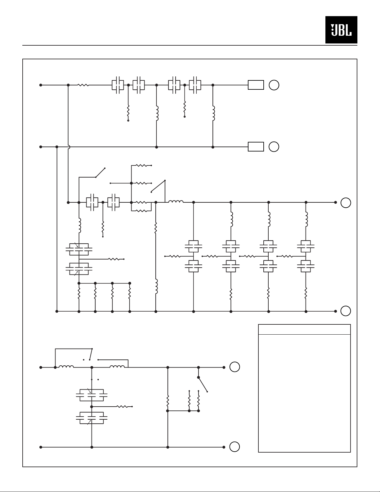
CAPACITOR LEGEND
U.H.F.
C1A, C2A: 3.0µF, 100V
C3A, C4A: 4.0µF, 100V
C1B, C2B, C3B, C4B: 0.01µF
H.F.
C1A, C2A: 24µF, 100V
C3A, C4A: 47µF, 100V
C3B, C4B: 1µF, 100V
C5A, C6A: 12µF, 100V
C7A, C8A: 24µF, 100V
C9A, C10A: 14µF, 100V
C11A, C12A: 2µF, 100V
C1B, C2B, C3C, C4C, C5B, C6B, C7B,
C8B, C9B, C10B, C11B, C12B: 0.01µF
L.F.
C1A, C2A: 82µF, 100V
C1B, C2B: 4µF, 100V
C1C, C2C: 0.01µF
C4CC4A
C4B
C1CC1A
C1B
C2CC2A
C2B
RED
BLK
Technical Manual
K2 S9800
JBL Consumer Products, 250 Crossways Park Drive, Woodbury, New York 11797
2Rev 1 2/2002
K2 S9800
SCHEMATIC
Page 3

36
41
28
22
16
2
11
3221
3
7
29
34
14
13
12
25
39
35
8
33
10
26
19
6
40
9
383120
2317
5
4
18
35 37
1
30
35
24
15
27
Technical Manual
K2 S9800
JBL Consumer Products, 250 Crossways Park Drive, Woodbury, New York 11797
3Rev 0 1/2002
K2 S9800
EXPLODED VIEW
TO SERVICE THE K2 S9800
The crossover network, after removal of the (6) faceplate screws,
should extract far enough out of the cabinet for service without wire or
driver removal.
Access to 9V bias batteries – metal plate removed by two thumbscrews
on the network faceplate.
Replacement or service of the high-frequency drivers requires access
through the woofer opening, following these steps:
NOTE: IT IS RECOMMENDED TWO PERSONS BE INVOLVED IN
K2S9800 DISASSEMBLY
1) Lay the loudspeaker down, on its back (drivers facing up), on a
padded surface.
2) Remove the grille.
3) Remove the (8) Phillips woofer screws.
4) The woofer is best extracted by inserting two 1/4 x 20 (3" or longer)
threaded machine screws into opposite sides of the two threaded
woofer screw openings.Caution: Only two of the holes are threaded;
they should be the top and bottom holes in the woofer frame.Thread
the bolts into the openings by hand, then pull upwards, lifting the woofer
from the counterbore.Then, while one person supports the woofer,
another can remove both connecting wires from the terminals. Set the
woofer aside.
5) Inside the cabinet, at the bottom of the HF horn, are the three
mounting screws; remove them.
6) The HF horn can now be removed from the cabinet by reaching in
and pushing the assembly out; remove both connecting wires from the
terminals. Set the HF assembly/horn aside.
7) The (10) screws holding the top cap assembly are now exposed;
remove them.
8) Lift the top cap assembly with UHF assembly off the cabinet.
NOTE:
a) When replacing the HF horn, to assist the (3) screw holes in lining
up properly, one person may have to depress the gasket by pressing
the horn assembly down into the cabinet, while the other replaces
the screws.
b) Remember to observe correct polarity when reattaching all driver wires.
Page 4

Technical Manual
K2 S9800
JBL Consumer Products, 250 Crossways Park Drive, Woodbury, New York 11797
4Rev 0 1/2002
K2 S9800
PARTS LIST
ITEM NO. DESCRIPTION QTY. PART NO.
1.
HF DRIVER HORN 1 337627-003
2. FRONT BAFFLE 1 338154-001
3. CROSSOVER NETWORK 1 337978-001
4. 15" WOOFER 1500AL 1 336308-001
5. HF DRIVER 435BE 1 337361-001
6. UHF DRIVER 045BE 1 336318-001
7. FOOT, BASE 4 338067-002
8. CABINET TOP 1 336921-003
9. UHF DRIVER HORN 1 337106-003
10. UHF DRIVER HOUSING 1 337534-003
11. FRONT GRILLE 1 337854-001
12. PORT TUBE, METAL 2 335202-002
13. PORT TUBE, FOAM 2 335203-001
14. PORT TUBE, PLASTIC, 1.57" 2 335339-003
15. GRILLE CUP 4 333249-001
16. DOWEL PIN 8 59266
17. 15" WOOFER GASKET 1 338073-001
18. HF HORN GASKET 1 337514-001
19. UHF GASKET, TOP 1 338166-001
20. UHF GASKET, BOTTOM 1 338165-001
21. CURVED, CABINET PANEL 1 337916-001
22. FOOT GASKET 4 338168-001
23. SCREW, MS, FLPH, 10-32X1.0 BLK, WFR TO ENCL 8 902201-016
24. SCREW, MS, BHXS, .25-20x1.50, BLK, HF DRVR TO HORN 3 902301-024
25. SCREW, MS, BHXS, .25-20x1.38, BLK, TOP TO ENCL 6 902301-022
26. SCREW, MS, BSH, 6-32X.25, SST, TWT HORN TO ANGLE BRKT/TOP 2 909904-004
27. SCREW, MS, PPH, 8-32x.625", BLK, TWT HOUSING TO TOP 4 900201-010
28. SCREW, MS, FLPH, .25-20, ZINC, FOOT TO BASE 4 910002-016
29. SCREW, PB, PPH, #6x.75, BLK, NETWORK TO ENCL 6 903401-012
30. SHIM 6 338078-001
31. ANGLE BRACKET FOR UHF DRIVER 2 338167-001
32. JBL LOGO 1 74714
33. STAND-OFF, .5" 4 338470-001
34. NYLON INSERT 6 332259-001
35. WASHER, FLAT, .25x.5", ZINC, 6X-TOP/ENCL, 3X-DRVR HF/HORN 13 337183-001
36. XOVER DAMPENING PAD 1 338528-001
37. BOLT, HEX HD, .25-20x.75, ZINC, ENCL TO HORN 4 47264
38. GASKET, WASHER, .312ODX.156ID 4 338536-001
39. STAND-OFF, 2.3" 2 338470-002
40. SCREW, MS, BSH, 6-32X.38, SST 2 909904-006
41. FOOT, SLIDE 4 338067-003
PACKING
42. OUTER CARTON 1 338313-001
43. PAD, END, TOP 1 338314-001
44. PAD, END, BOT 1 338315-001
45. OWNER’S MANUAL 1 338316-001
46. FOOT, SPIKE 4 338067-004
47. FOOT, BASE, FLOOR 4 338067-005
 Loading...