

Page 1

GTO Series
301.1
301.1II
1 CHANNEL POWER AMPLIFIER
SERVICE MANUAL
JBL Consumer Products
250 Crossways Park Dr.
Woodbury, New York 11797 R
ev2AA10/2005
Page 2

1
Power Amplifier GTO 301.1/301.1II
- CONTENTS -
SPECIFICATIONS ………………………………….……..1
FEATURES/TEST CONDITIONS……..…………………2
INSTALLATION………………….……...……..…...…...…3
CONNECTIONS………………….……...……..…...…..…4
SET-UP/CONTROLS ……..………………..…….….…...5
INSTALLING NEON TUBES..…….…….………………..5
BASIC TROUBLESHOOTING..…….…….………………6
TYPICAL SYSTEM WIRING..…….…….……………..…7
EXPLODED VIEW/PARTS LIST…….….….…………....8
MECHANICAL PARTS LIST..…….…….……………......9
AMPLIFIER BLOCK DIAGRAM…………………….……10
P.C.B. DRAWINGS….……………………………….…….11
ELECTRICAL PARTS LIST ..……….……….…….….…13
VERSION II ELECTRICAL PARTS LIST ADDENDUM….……….16
IC/TRANSISTOR PINOUTS..……..….…….….….….…..17
GTO 301.1 SCHEMATICS………..…………..…..……...20
GTO 301.1II SCHEMATICS………...……….…………...22
PACKING……..……………………………......................24
GTO 301.1/ GTO 301.1II Specifications
Output Power: 204W RMS x 1 channels @ 4 ohms; ≤1% THD + N
(14.4V supply) 294W RMS x 1 channels @ 2 ohms; ≤1% THD + N
Signal-to-noise ratio: 77dBA (reference 1W into 4 ohms)
Dynamic power: 320W @ 2 ohms
Effective damping factor: 6.39 @ 4 ohms
Frequency response: 10Hz – 302Hz (–3dB)
Maximum input signal: 4.7V
Maximum sensitivity: GTO 301.1 - 220mV
GTO 301.1II - 75mV
DC Offset <50mV (-50%)
Output regulation: .098dB @ 4 ohms
Idle Current 0.90A
Input Impedance 22kΩ
Max Current Draw 22A @ 4 ohms
39A @ 2 ohms
Dimensions: 11 5/8 x 12 5/16 x 2 3/8” (L x W x D)
(295mm x 313mm x 60mm)
Fuses: 30A
JBL continually strives to update and improve existing products, as well as create new ones. The specifications and details in
this and related JBL publications are therefore subject to change without notice.
Page 3
GTO 301.1/301.1II
2
Page 4
INSTALLATION
3
GTO 301.1/301.1II
WARNING: Playing loud music in an
automobile can hinder your ability to hear
traffic and permanently damage your
hearing. We recommend listening at low or
moderate levels while driving your car. JBL
accepts no liability for hearing loss, bodily
injury or property damage resulting from
the use or misuse of this product.
IMPORTANT: To get the best
performance from your JBL Grand Touring
Series amplifiers, we strongly recommend
that installation be entrusted to a qualified
professional. Although these instructions
explain how to install GTO amplifiers in a
general sense, they do not show specific
installation methods that may be required
for your particular vehicle. If you do not
have the necessary tools or experience,
do not attempt the installation yourself.
Instead, please ask your authorized JBL
car audio dealer about professional
installation.
INSTALLATION
WARNINGS AND TIPS
• Always wear protective eyewear when
using tools.
•Turn off the audio system and other
electrical devices before you start.
Disconnect the (–) negative lead from
your vehicle’s battery.
• Check clearances on both sides of
a planned mounting surface before
drilling any holes or installing any
screws. Remember that the screws
can extend behind the surface.
• At the installation sites, locate and
make a note of all fuel lines, hydraulic
brake lines, vacuum lines and electrical
wiring. Use extreme caution when cutting or drilling in and around these areas.
• Before drilling or cutting holes, use a
utility knife to remove unwanted fabric
or vinyl to keep material from snagging
in a drill bit.
• When routing cables, keep input-signal
cables away from power cables and
speaker wires.
•When making connections, make
certain they are secure and properly
®
insulated.
• If the amplifier’s fuse must be replaced,
use only the same type and rating as
that of the original. Do not substitute
another kind.
CHOOSING A LOCATION
AND MOUNTING THE
AMPLIFIER
Choose a mounting location in the trunk
or cargo area where the amplifier will not
be damaged by shifting cargo. Amplifier
cooling is essential for proper amplifier
operation. If the amplifier is to be installed
in an enclosed space, make sure there is
sufficient air circulation for the amplifier
to cool itself.
When mounting the amplifier under a
seat, ensure that it is clear of all moving
seat parts and does not affect the seat
adjustments. Mount the amplifier so it
is not damaged by the feet of backseat
passengers. Make sure that the amplifier
is mounted securely using nuts and bolts
or the supplied mounting screws.
Mount the amplifier so that it remains
dry – never mount an amplifier outside
the vehicle or in the engine compartment.
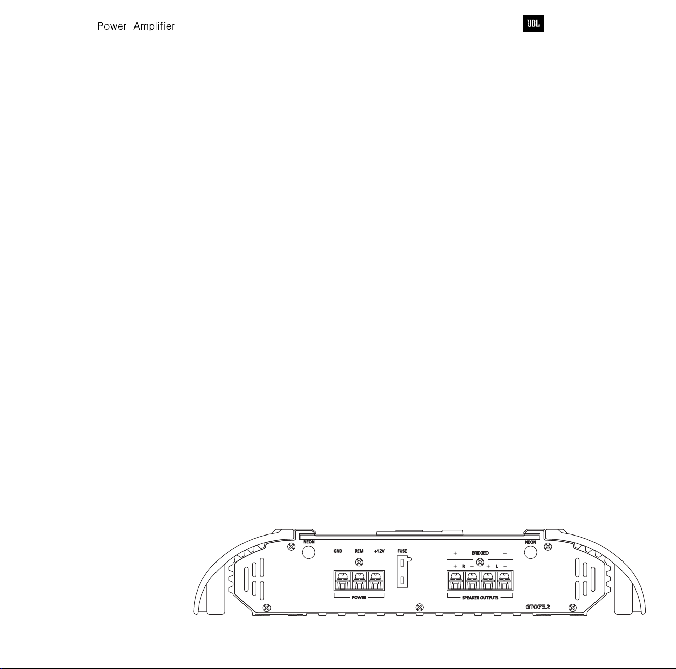
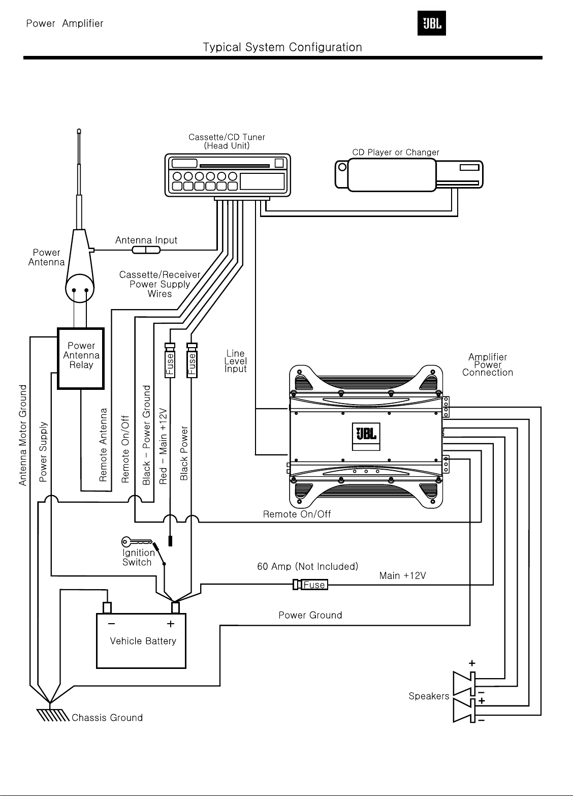
Figure 1. Terminal connection end plate.
POWER CONNECTIONS
The GTO amplifiers are capable of
delivering extremely high power levels,
and require a heavy-duty and reliable
connection to the vehicle’s electrical system
in order to perform optimally. See Figure 1
for connection location. Please adhere to
the following instructions carefully:
Ground Connection
Connect the amplifier’s Ground (GND)
terminal to a solid point on the vehicle’s
metal chassis, as close to the amplifier
as possible. Refer to the chart below to
determine minimum wire-gauge size. Scrape
away any paint from this location; use a startype lock washer to secure the connection.
Power Connection
Connect a wire (see chart at right for
appropriate gauge) directly to the vehicle’s
positive battery terminal, and install an
appropriate fuse holder within 18" of the
battery terminal.
this time. Route the wire to the amplifier’s
location, and connect it to the amplifier’s
Positive (+12V) terminal. Be sure to use
appropriate grommets whenever routing
wires through the firewall or other sheet
Failure to adequately protect the
metal.
positive wire from potential damage may
result in a vehicle fire.
routing and connecting this wire, you may
install the fuse at the battery.
Remote Connection
Connect the amplifier’s Remote (REM)
terminal to the source unit’s Remote TurnOn lead using a minimum of 18-gauge wire.
NOTE: When using the speaker level
inputs, connect the remote (REM) terminal
to the source unit. If your source unit does
not have a remote turn-on connection,
connect the amplifier’s (REM) terminal to
the vehicle’s accessory circuit.
Do not install the fuse at
When you are done
Speaker Connections
Refer to the application guides on the
pages that follow. Speaker connections
should be made using a minimum of
16-gauge wire.
NOTE: When using the high-level inputs,
the AUX outputs can be used to pass a
line-level signal to another amplifier.
Wire Gauge Chart
Amplifier Maximum Minimum
Model Current Draw Wire Gauge
AWG
AWG
GTO301.1 40A #8 AWG
AWG
These recommendations assume 7' – 10'
wire runs. If your installation differs markedly, you will need to adjust the wire
gauge accordingly.
IMPORTANT NOTE: If you are planning
to use optional neon tubes, install them
before making any electrical connections
to the amplifier (refer to“Installing Neon
Tubes” on page 5).
Page 5

CONNECTIONS – GTO301.1/GTO301.1II
GTO Amplifier
(partial end panel)
Subwoofer
–
+
GTO Amplifier
(partial end panel)
Subwoofer Subwoofer
+
–
–
+
4
The GTO subwoofer amplifiers are
single-channel amplifiers. There are
two sets of terminals to make it easy
to connect multiple woofers. Either
set of (+/–) terminals may be used
when connecting woofers.
To the right are two application
diagrams to help plan your subwoofer
system installation.
show how to configure the GTO
subwoofer amplifiers
Figures 2 and 3
GTO 301.1/301.1II
NOTE: For simplicity, Figures 2 and 3
do not show power, remote and input
connections.
NOTE: Minimum speaker load is
2 ohms.
Figure 2. GTO subwoofer amplifier with two woofer connections.
Figure 3. GTO subwoofer amplifier with one woofer connection.
Page 6
INSTALLATION AND SETUP
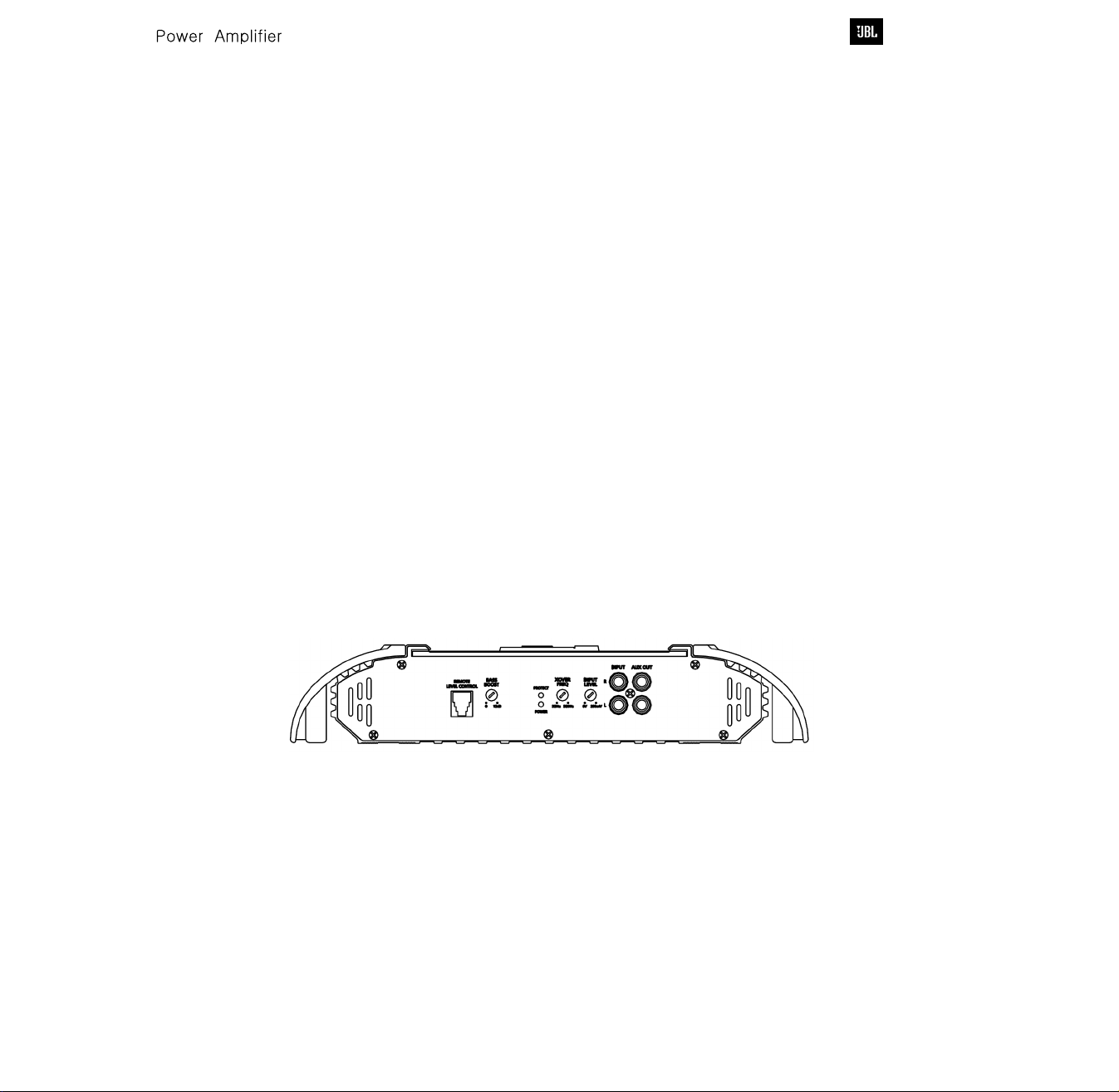
SETTING THE
CROSSOVER(S)
SETTING INPUT
SENSITIVITY
1. Initially turn the INPUT LEVEL control(s)
to minimum (counter clockwise).
2. Reconnect the (–) negative lead to the
vehicle’s battery. Apply power to the
audio system and play a dynamic music
track.
3. On the source unit, increase the volume
control to 3/4 volume. Slowly increase
the INPUT LEVEL control(s) toward three
o’clock until you hear slight distortion
in the music. Then reduce the INPUT
LEVEL slightly until distortion is no
longer heard.
NOTE: After the source unit is on, red LEDs
(on the top panel) will light, indicating the
amplifier is on. If not, check the wiring,
especially the remote connection from the
source unit. Also refer to “Troubleshooting”
on the next page.
REMOTE LEVEL CONTROL
SETTING THE BASS BOOST
AUX OUTPUT
NOTE: When using the high-level inputs,
the AUX outputs can be used to pass a
line-level signal to another amplifier.
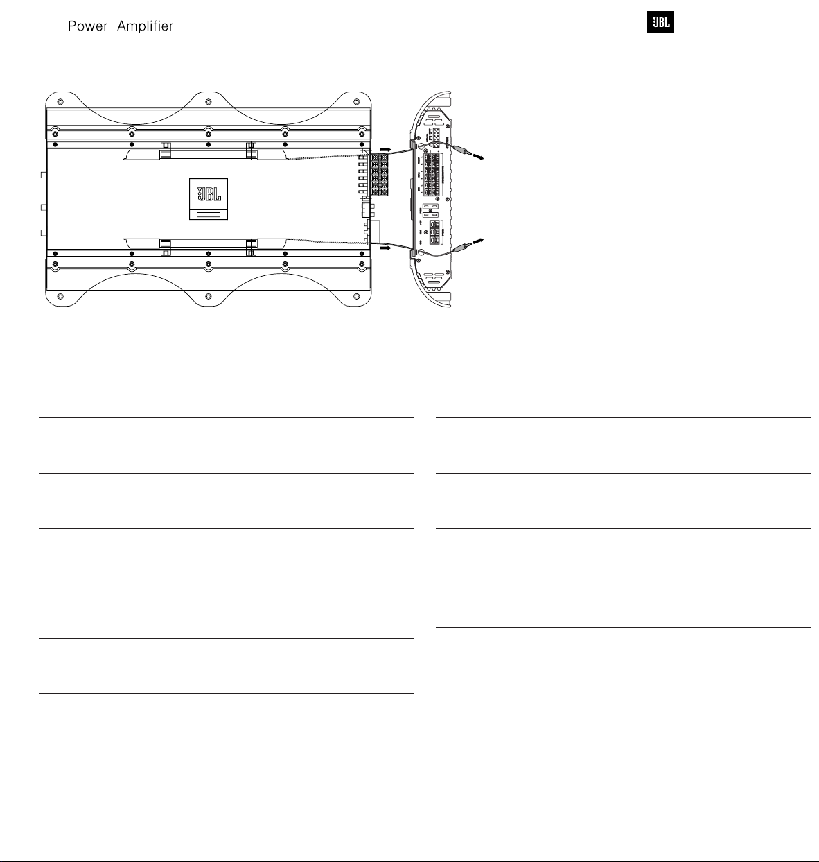
INSTALLING NEON TUBES
(OPTIONAL)
1. Using a Phillips screwdriver, remove all
screws on the amplifier’s output/power
end panel and set them aside.
2. Using a 3⁄ 32-inch Allen wrench, remove
only the screws on the amplifier’s (top)
clear cover and set them aside.
3. Remove the end panel and slide the
cover off. Set both parts aside.
4. Locate the enclosed hardware bag and
remove the four clips. Each clip has a
square end and a larger round end.
Using a round end, press two clips onto
each neon tube (e.g., Street Glow AN9
or equivalent), as shown in
Figure 13.
5. For each tube, align both clips so the
square ends slide onto an exposed
extrusion edge, as shown in Figure 9.
Do not cover any screw holes. When
installed correctly, each neon tube will
sit under an extrusion and not be visible
when viewed from directly above.
6. Route each neon tube’s power cable
through its respective NEON hole on the
end panel (see
Figure 13).
7. Slide the cover back into place and reinstall its screws. Then, replace the end
panel and reinstall its screws.
8. Finish the installation of the neon tubes
as instructed in their owner’s manual.
Figure 12.
5
GTO 301.1/301.1II
Determine your system plans and set the
crossover mode switch accordingly.
Initially set the crossover frequency
control midway. While listening to music,
adjust the crossover for the least
perceived distortion from the speakers,
allowing them to reproduce as much
bass as possible.
Systems using a separate subwoofer set
the crossover mode to HP (high pass) for
your full-range speakers. Adjust the
crossover frequency to limit bass and
provide increased system volume with
less distortion.
For subwoofers, choose the highest
frequency that removes vocal information
from the sound of the subwoofer.
All three GTO subwoofer
amplifiers have inputs for an optional
remote level control (RLC). This will allow
the amplifier’s input level to be adjusted
from the listening position. Connect the
optional remote level control using the
RJ-11 jack on the side of the amplifier.
Install the control module in the front of
the vehicle within easy reach of the driver.
Under the dash or in the center console
are both suitable locations.
All three GTO subwoofer amplifiers
are all equipped with a bassboost control. This allows you to adjust the
bass output of your system at 50Hz up to
12dB and enhance low frequency.
All three GTO subwoofer amplifiers are
equipped with full-range outputs that can
be used to connect additional amplifiers.
Page 7
INSTALLATION AND SETUP
To Neon
Power
Supply
To Neon
Power
Supply
6
Figure 13. Installing neon tubes in a JBL GTO amplifier.
TROUBLESHOOTING
GTO 301.1/301.1II
SYMPTOM LIKELY CAUSE SOLUTION
No audio No voltage at BATT+ Check voltages at
(POWER LED or REM terminals, amplifier terminals
is off) or bad or no ground with VOM
connection
No audio DC voltage on Amplifier may need
(PROTECT LED amplifier output service; see enclosed
flashes every warranty card for
4 seconds) service information
No audio Amplifier is Make sure amplifier
(PROTECT overheated cooling is not blocked
LED is on) at mounting location;
verify speaker system
impedance is within
specified limits (see
“Specifications” on
the next page)
No audio Voltage less than 9V on Check vehicle
(PROTECT BATT+ connection charging system for
and POWER defective voltage
LEDs flash) regulator
SYMPTOM LIKELY CAUSE SOLUTION
No audio Voltage more than 16V Check vehicle
(PROTECT or less than 8.5V on charging system for
LED is on) BATT+ connection defective voltage
Distorted audio Input sensitivity is Check INPUT
Distorted audio Short circuit in Remove speaker leads
and PROTECT speaker or wire one at a time to locate
LED flashes shorted speaker or
Music lacks Speakers are not Check speaker
“punch” connected properly connections for
regulator
not set properly, or LEVEL setting; or
amplifier or source check speaker wires
unit is defective for shorts or grounds
wire, then repair
proper polarity
Page 8
GTO 301.1/301.1II
7
Grand TouringGrand Touring
Page 9

GTO 301.1/301.1II Exploded View
8
GTO 301.1/301.1II
Page 10

Mechanical Parts List
9
GTO 301.1/301.1II
Page 11

GTO301.1/GTO301.1II BLOCK DIAGRAM
10
GTO 301.1/301.1II
Page 12

GTO 301.1/301.1II
11
TH01
FTD5-350
YG225D2
D41
YG225D2
D42
10m/m
Q198
C3198GR
Q199
C3198GR
C199
TIP36C
C3200GR
Q192
Q172
TIP36C
Q191
TIP36C
Q190
PAM629-01
REV.0
J57 10m/m
J58
10m/m
J60 10m/m
J59
10m/m
J56
100/16V
C3198GR
Q219
1/50V
C220
15K
R220
6m/m
J100
10K
R219
4.7/50V
C219
150K
R221
150
R222
104(M)
C197
55m/m
R199
0.1/3W
22m/m
22m/m
22m/m
0.1/3W
0.1/3W
22m/m
J39
J40
J41
680/2W
BJ03
20m/m
56K
15m/m
10
10
10
J101
MOD01
623PCB4-B
4.7/0.5W
19m/m
19m/m
19m/m
J69 15m/m
30K
R215
15K
R216
U105
R223
TER02
DST0014-00
20m/m
20m/m
20m/m
R198
R197
4.7/0.5W
CL-200C
L196
R196
J4225m/m
J43
25m/m
25m/m
J44
25m/m
J45
25m/m
J46
25m/m
J47
25m/m
J48
25m/m
J49
J50
J51
J52
J5325m/m
25m/m
J54
J55
J63
J66
J65
J68
15m/m
15m/m
20m/m
20m/m
R195
J94
R192
J95
J96
J97
R194
R191
R193
R190
NJM13600
X
C61
J61
J62
20m/m
20m/m
910F
R157
100/16V
C159
39KF
R158
C158
100/0.5W
R174
10/0.5W
R175
6m/m
J91
6m/m
J92
6m/m
J93
270P
C175
A1023Y
Q175
R168
A1023Y
Q174
R167
A1023Y
Q173
560
R166
47/16V
C212
10KF
R213
510F
R214
510
R217
10K
R218
47/16V
C223
1K
R227
VR103
20KB
BASSBOOST
C51
470/63V
470/63v
47P
560
560
6m/m
J102
1SS133
J88
J10320m/m
U106
1K
R92
C3198GR
Q90
22K
R91
47K
R90
10
R15
6m/m
J30
A1266GR
Q12
24K
R21
6m/m
J31
100/16V
C12
68K
R25
102(M)
C21
24K
R22
6m/m
J32
910
R16
4.7K
R02
C3198BL
Q21
10K
R14
104P
C22
1K
R31
D11
10/25V
C15
15K
R35
47/25V
C16
12.5m/m
J35
L02
CL-500
C3200GR
Q156
22KF
R171
10m/m
J90
1SS133
D152
1SS133
D151
680
R156
100/63V
C157
473P
C156
120
R172
10m/m
C163
C1027Y
Q171
820
R173
1.5K
R163
R228
NJM2068LD
C228
R232
150K
R230
104(M)
C229
6.8K
R229
104(M)
C227
R04
C11
C3198GR
Q02
R05
A1266GR
Q11
R12
C14 47/16V
R13
J29
10/16V
C06
A1023Y
Q01
R01
100/16V
C13
10/0.5W
R03
R32
R33
A1268GR
Q22
R34
12.5m/m
CL-500
L01
J34
C63
C3200GR
Q153
C3200GR
Q152
22KF
R152
C152
2.2/50V
C151
R151
1/50V
R149
Q151
5.6KF
R150
2.2/50V
20m/m
J89
39K
47P
1K
LED01
R913
TOL-30aSBaCAa-B2
LED02
100/16V
56K
J305
J304
J303
8.2K
R63
R11
4.7K
430K
3.9K
10K
C60
6m/m
R62
U01
10.5KF
R60
1SS133
D03
TL494CN
A1266GR
Q33
220/0.5W
R51
220/0.5W
R41
A1266GR
Q23
1SS133
D04
J28
4.7K
22K
33K
15K
25m/m
J33
473P
C62
J70
15m/m
J71
J7525m/m
68P
10K
100K
J77
J108
J78 25m/m
15m/m
J79
J8010m/m
C150
J104
J105
17.5m/m
J106
17.5m/m
J107
C225
R226
1K
HNRD-3401L
6m/m
6m/m
6m/m
7.5m/m
J08
J07
104P
4.7KF
15m/m
SCREW
4
8
12.5m/m
J36
12.5m/m
J37
12.5m/m
J38
3300/63V"HC"
15m/m
GTO301.1
330/16V
C921
1N4744
D921
330/16V
C913
20m/m
J8110m/m
J8210m/m
J8310m/m
22m/m
22m/m
5.6K
R225
10K
R224
683(M)
C226
SCREW
823(M)
5.6K
50KC
1K
R923
FH01
J01
J02
7.5m/m
WF-9402
7.5m/m
7.5m/m
7.5m/m
7.5m/m
7.5m/m
7.5m/m
D911
VR102
LPF
J03
7.5m/m
J06
J05
J04
J330
J300
J301
7.5m/m
7.5m/m
7.5m/m
J302
J306
J307
J308
CL-300
L03
2200/25V"WL"
C04
C03 104P
J09
J11
J12
J13
J10
10m/m
10m/m
10m/m
10m/m
10m/m
2200/25V"WL"
C05
37PHI
J73
17.5m/m
17.5m/m
330/16V
22K
6m/m
A1268GR
A1268GR
100P
1.5K
473P
A1268GR
1K
102P
A1268GR
10KF
R211
102P
C211
2KF
R212
6m/m
J109
4.7KF
R208
470P
C108
4.7KF
R108
6m/m
J110
15K
R250
VR101
R210
C52
47
750F
T01
J74
U103
C210
20KB
VOLUME
20m/m
D161
D160
R187
D187
C155
2
6
1SS133
C187
C3200GR
Q187
1SS133
J120
C165
C1027Y
Q165
C1027Y
Q164
C1027Y
Q163
330/16V
C923
NJM2068LD
47/16V
R209
3
5(0.7x9):17(0.7x4):10(0.7x1)
7
J72
C911
R160
1N4744
J85
Q162
Q161
C160
R162
R161
6m/m
J76
C154
Q154
R153
C153
J8410m/m
Q155
17.5m/m
J108
NJM2068LD
U104
DST0013-00
3
6m/m
X
6m/m
6m/m
C01
D01
2
2
1
5
100/2W
R30
3300/63V"HC"
1SS133
100P
15K
6m/m
100/63V
270P
5m/m
J86
6m/m
J87
47KF
R106
22P
C106
9.4KF
R207
10P
C104
47KF
R103
47KF
R102
47KF
R105
22P
C105
6m/m
J111
9.4KF
R107
100
22/16V
C103
C102
22KF
R101
C101
102P
R
IN4004
D02
C801
473P
1N5404
BJ01
47
BJ02
47
25m/m
1K
47
17.5m/m
17.5m/m
17.5m/m
222(M)
C08
473P
C33
R6110K
3RD
FR154
D54
FR154
FR154
D52
D53
473P
C53
220/2W
220/2W
R921
R911
10
1.5K
0.1/3W
10
R164
100/0.5W
R165
10/0.5W
0.1/3W
10
0.1/3W
22P
C205
47KF
R205
10KF
R240
NJM2068LD
47KF
R202
10P
C204
6m/m
J112
47KF
R203
10KF
R140
22P
U101
C206
47KF
22/16V
R206
22/16V
22/16V
C202
C203
22KF
R201
C201
102P
LL
R
DJB-554A
TER01
J1417.5m/m
J1517.5m/m
R54
J1617.5m/m
J1717.5m/m
R53
J18
J19
47
J2017.5m/m
J2117.5m/m
47
J22
J2317.5m/m
1K
47
J2417.5m/m
J2517.5m/m
105(M)"TL"
C31
3RD.
6m/m
J26
C67
FR154
D51
C57
C82
Q82
C83
15m/m
J27
R182
R186
R185
R181
R184
R180
R183
NJM2068LD
U102
4.7/50V
C143
R144
100K
55m/m
R55
R52
R45
R44
R42
R43
105(M)"TL"
W01
D81
47/50V
R81
47/50V
22P
10/50V
Q182
Q181
Q180
104P
C912
104P
C922
6m/m
J113
22P
C241
10KF
R241
1K
R242
1K
R142
1K
R243
22P
C141
10KF
R141
1K
R143
C243
R244
100K
RCA101
FQP50N06
Q55
FQP50N06
Q54
FQP50N06
Q53
FQP50N06
Q45
FQP50N06
Q44
FQP50N06
C32
Q43
WIRE
X
1SS133
1SS133
220K
10K
J108
TIP35C
1
TIP35C
1
TIP35C
1
4.7/50V
3
D80
R80
C182 220P
C180 220PC181 220P
Page 13
GTO 301.1/301.1II
12
Q55
Q54
Q53
Q45
Q44
Q43
Q182
Q181
Q180
C210
FH01
L03
J28
T01
J73
J72
GTO301.1
J74
C921
C911
R160
D911
R210
D921
C913
J76
J77
J78
J83
J84
J108
U104
VR102
R923
Q162
Q161
C160
R161
C154
Q155
R162
R153
C153
J85
Q154
C211
R212
J109
R208
C108
R108
J110
R250
R51
C62
R224
C226
C225
R41
R225
R04
C11
Q02
R92
R05
Q90
Q11
R91
R12
R63
R11
C60
R62
R60
D03
Q33
Q23
D04
J33
J71
J75
J79
J80
J81
J82
J104
J105
J106
J107
R226
LED01
LED02
J70
Q153
Q152
R33
R152
C152
C151
R151
R149
Q151
R150
C150
R90
R15
C14
J30
R13
J29
Q12
U01
R21
J31
C12
R25
C21
R22
J32
C06
R16
R02
Q01
R01
Q21
R14
C13
C22
R03
R31
D11
R32
C15
R35
Q22
R34
C16
L01
J34
J35
C63
L02
Q156
R171
J90
D152
D151
R156
C157
C156
R172
J88
C163
Q171
R173
R163
J89
R228
C228
R232
R230
C229
U106
R229
C227
R913
TER02
J39
J40
J41
R198
R197
C197
R196
L196
BJ03
J42
J43
J44
J45
J46
J47
J48
J49
R157
C159
R158
C158
C175
Q175
R168
Q174
R167
Q173
R166
J102
VR103
J50
J51
J52
J53
J54
J55
R199
J69
J68
R213
R214
R217
R218
C223
R227
C212
J66
J65
J62
J63
R195
J94
R192
J95
J96
J97
R194
R191
R193
R190
R215
R216
U105
R223
MOD01
J61
C51
C61
R174
R175
J91
J92
J93
J103
J101
Q219R211
C220
R220
J100
R219
C219
R221
R222
TH01
J58
J57
D41
D42
J59
J60
J56
Q198
Q199
C199
Q192
Q172
Q191
Q190
TER01
C01
D02
J301
J302
C801
D01
C04
BJ01
R55
R54
C32
C31
W01
D80
R80
R81
C912
C922
J113
C241
R241
R242
R142
R243
C141
R141
R143
R244
3RD.
J26
D81
D51
C67
C57
C82
Q82
C83
J27
R184
R183
U102
C243
C143
R144
R185
BJ02
J14
J15
J16
J17
R52
R53
J18
J19
R45
J20
J21
R44
J22
J23
R42
R43
J24
J25
C08
R61
C33
3RD
D54
D53
D52
R921
R911
R182
R186
R181
R164
R165
R180
C205
R205
R240
R202
C204
J112
R203
R140
U101
C206
R206
C203
C202
R201
C201
RCA101
C03
C05
R30
C52
C53
D161
D160
C187
Q187
R187
D187
J120
C155
C165
Q165
J86
Q164
J87
Q163
R106
C923
C106
R207
C104
R103
R102
R105
C105
J111
U103
R107
R209
C103
C102
R101
VR101
C101
Page 14

13
GTO 301.1/301.1II
FET-00-00045 F.E.T MUTTING J-FET J108 Q82,151 2
TRS-00-00087 TRANSISTOR SMALL SIGNAL PNP KTA1023Y Q01,173,174,175 4
TRS-00-00088 TRANSISTOR SMALL SIGNAL NPN KTC1027Y Q163,164,165,171 4
TRS-00-00091 TRANSISTOR SMALL SIGNAL PNP KTA1268GR Q22,154,155,161,162 5
TRS-00-00111 TRANSISTOR SMALL SIGNAL NPN KTC3200GR Q152,153,156,187 4
TRS-00-00090 TRANSISTOR SMALL SIGNAL PNP KTA1266GR Q11,12,23,33 4
TRS-00-00110 TRANSISTOR SMALL SIGNAL NPN KTC3198GR Q02,90,198,199,219 5
TRS-00-00109 TRANSISTOR SMALL SIGNAL NPN KTC3198BL Q21 1
DIO-00-00108 DIODE FAST RECOVERY FR154 D51,52,53,54 4
DIO-00-00003 DIODE RECTIFIER IN4004 D02 1
DIO-00-00006 DIODE SWITCHING SIGNAL 1SS133 /1N4148 D03,04,11,80,81,151,152,160,161,187 10
RES-00-00549 RESISTOR METAL FILM 1/5WF 510 OHM R214 1
RES-00-00577 RESISTOR METAL FILM 1/5WF 750 OHM R210 1
RES-00-00590 RESISTOR METAL FILM 1/5WF 910 OHM R157 1
RES-00-00482 RESISTOR METAL FILM 1/5WF 2K OHM R212 1
RES-00-00523 RESISTOR METAL FILM 1/5WF 4.7K OHM R62,108,208 3
RES-00-00545 RESISTOR METAL FILM 1/5WF 5.6K OHM R150 1
RES-00-00589 RESISTOR METAL FILM 1/5WF 9.4K OHM R107,207 2
RES-00-00402 RESISTOR METAL FILM 1/5WF 10K OHM R140,141,211,213,240,241 6
RES-00-00399 RESISTOR METAL FILM 1/5WF 10.5K OHM R60 1
RES-00-00467 RESISTOR METAL FILM 1/5WF 22K OHM R101,152,171,201 4
RES-00-00517 RESISTOR METAL FILM 1/5WF 39K OHM R158 1
RES-00-00537 RESISTOR METAL FILM 1/5WF 47K OHM R102,103,105,106,202,203,205,206 8
RES-00-00610 RESISTOR CARBON FILM 1/5WJ 10 OHM R15,180,181,182,190,191,192 7
RES-00-00716 RESISTOR CARBON FILM 1/5WJ 47 OHM R43,44,45,53,54,55,162 7
RES-00-00606 RESISTOR CARBON FILM 1/5WJ 100 OHM R209 1
RES-00-00615 RESISTOR CARBON FILM 1/5WJ 120 OHM R172 1
RES-00-00622 RESISTOR CARBON FILM 1/5WJ 150 OHM R222 1
RES-00-00723 RESISTOR CARBON FILM 1/5WJ 510 OHM R217 1
RES-00-00728 RESISTOR CARBON FILM 1/5WJ 560 OHM R166,167,168 3
RES-00-00741 RESISTOR CARBON FILM 1/5WJ 680 OHM R156 1
RES-00-00756 RESISTOR CARBON FILM 1/5WJ 820 OHM R173 1
RES-00-00761 RESISTOR CARBON FILM 1/5WJ 910 OHM R16 1
RES-00-00633 RESISTOR CARBON FILM 1/5WJ 1K OHM R31,42,52,92,142,143,153,227,232,242 13
R243,913,923
RES-00-00598 RESISTOR CARBON FILM 1/5WJ 1.5K OHM R161,163,186 3
RES-00-00676 RESISTOR CARBON FILM 1/5WJ 3.9K OHM R12 1
RES-00-00702 RESISTOR CARBON FILM 1/5WJ 4.7K OHM R01,02,11 3
RES-00-00720 RESISTOR CARBON FILM 1/5WJ 5.6K OHM R225,226 2
RES-00-00734 RESISTOR CARBON FILM 1/5WJ 6.8K OHM R229 1
RES-00-00751 RESISTOR CARBON FILM 1/5WJ 8.2K OHM R05 1
RES-00-00608 RESISTOR CARBON FILM 1/5WJ 10K OHM R13,14,61,81,151,218,219,224 8
RES-00-00623 RESISTOR CARBON FILM 1/5WJ 15K OHM R34,35,187,216,220,250 6
RES-00-00658 RESISTOR CARBON FILM 1/5WJ 22K OHM R32,91,160 3
RES-00-00663 RESISTOR CARBON FILM 1/5WJ 24K OHM R21,22 2
RES-00-00680 RESISTOR CARBON FILM 1/5WJ 30K OHM R215 1
RES-00-00687 RESISTOR CARBON FILM 1/5WJ 33K OHM R33 1
RES-00-00697 RESISTOR CARBON FILM 1/5WJ 39K OHM R228 1
RES-00-00714 RESISTOR CARBON FILM 1/5WJ 47K OHM R90 1
RES-00-00730 RESISTOR CARBON FILM 1/5WJ 56K OHM R04,199 2
Page 15

14
GTO 301.1/301.1II
RES-00-00742 RESISTOR CARBON FILM 1/5WJ 68K OHM R25 1
RES-00-00604 RESISTOR CARBON FILM 1/5WJ 100K OHM R144,149,244 3
RES-00-00620 RESISTOR CARBON FILM 1/5WJ 150K OHM R221,230 2
RES-00-00654 RESISTOR CARBON FILM 1/5WJ 220K OHM R80 1
RES-00-00706 RESISTOR CARBON FILM 1/5WJ 430K OHM R63 1
RES-00-00053 RESISTOR METAL FILM 1/2WJ 4.7 OHM R196,197 2
RES-00-00018 RESISTOR METAL FILM 1/2WJ 10 OHM R03,165,175 3
RES-00-00016 RESISTOR METAL FILM 1/2WJ 100 OHM R164,174 2
RES-00-00038 RESISTOR METAL FILM 1/2WJ 220 OHM R41,51 2
ELC-00-00218 CAPACITOR ELECTROLYTIC "SMS" 1/50V C163,220 2
ELC-00-00223 CAPACITOR ELECTROLYTIC "SMS" 2.2/50V C150,151 2
ELC-00-00229 CAPACITOR ELECTROLYTIC "SMS" 4.7/50V C143,219,243 3
ELC-00-00195 CAPACITOR ELECTROLYTIC "SMS" 10/16V C06 1
ELC-00-00203 CAPACITOR ELECTROLYTIC "SMS" 10/25V C15 1
ELC-00-00220 CAPACITOR ELECTROLYTIC "SMS" 10/50V C83 1
ELC-00-00197 CAPACITOR ELECTROLYTIC "SMS" 22/16V C102,103,202,203 4
ELC-00-00198 CAPACITOR ELECTROLYTIC "SMS" 47/16V C14,210,212,223 4
ELC-00-00205 CAPACITOR ELECTROLYTIC "SMS" 47/25V C16 1
ELC-00-00227 CAPACITOR ELECTROLYTIC "SMS" 47/50V C57,67 2
ELC-00-00199 CAPACITOR ELECTROLYTIC "SMS" 100/16V C11,12,13,159,199 5
ELC-00-00201 CAPACITOR ELECTROLYTIC "SMS" 330/16V C911,913,921,923 4
MYC-00-00020 CAPACITOR MYLAR 5% 100V 102(M) J C21 1
MYC-00-00031 CAPACITOR MYLAR 5% 100V 222(M) J C08 1
MYC-00-00044 CAPACITOR MYLAR 5% 100V 683(M) J C226 1
MYC-00-00045 CAPACITOR MYLAR 5% 100V 823(M) J C225 1
MYC-00-00094 CAPACITOR MYLAR 5% 100V 104(M) J C197,227,229,35 4
MYC-00-00085 CAPACITOR MYLAR 5% 63V "TL" 105(M) J C31,32,36 3
CEC-00-00074
CEC-00-00077 CAPACITOR CERAMIC DISK 50V 10P F C104,204 2
CEC-00-00090 CAPACITOR CERAMIC DISK 50V 22P F C82,105,106,141,205,206,241 7
CEC-00-00103 CAPACITOR CERAMIC DISK 50V 47P F C158,228 2
CEC-00-00108 CAPACITOR CERAMIC DISK 50V 68P F C152 1
CEC-00-00073 CAPACITOR CERAMIC DISK 50V 100P F C160,187 2
CEC-00-00092 CAPACITOR CERAMIC DISK 50V 270P F C165,175 2
CEC-00-00101 CAPACITOR CERAMIC DISK 50V 470P F C108 1
CEC-00-00074 CAPACITOR CERAMIC DISK 50V 102P F C101,153,201,211,37 5
CEC-00-00102 CAPACITOR CERAMIC DISK 50V 473P F C33,53,63,154,156,801 6
CEC-00-00076 CAPACITOR CERAMIC DISK 50V 104P F C03,22,60,912,922 5
CEC-00-00086 CAPACITOR CERAMIC DISK 50V 220P F C180,181,182 3
JUP-00-00051 JUMPER 0OHM JUMPER 5m/m J86 1
JUP-00-00043 JUMPER 0OHM JUMPER 6m/m J26,29,30,31,32,76,85,87,91,92 25
J93,100,102,109,110,111,112,113,120,300
J301,302,303,304,305
JUP-00-00044 JUMPER 0OHM JUMPER 7.5m/m J01,02,03,04,05,06,07,08,306,307 12
J308,330
JUP-00-00045 JUMPER 0OHM JUMPER 10m/m J09,10,11,12,13,56,57,58,59,60 17
J80,81,82,83,84,88,90
JUP-00-00046 JUMPER 0OHM JUMPER 12.5m/m J34,35,36,37,38 5
JUP-00-00047 JUMPER 0OHM JUMPER 15m/m J27,28,66,68,69,70,71,79,94 9
JUP-00-00048 JUMPER 0OHM JUMPER 17.5m/m J14,15,16,17,18,19,20,21,22,23 17
J24,25,72,73,106,107,108
JUP-00-00074 JUMPER 0OHM JUMPER 19m/m J50,51,52 3
JUP-00-00049 JUMPER 0OHM JUMPER 20m/m J39,40,41,55,61,62,63,65,74,77 12
J89,103
Page 16

15
GTO 301.1/301.1II
JUP-00-00075 JUMPER 0OHM JUMPER 22m/m J95,96,97,101,104,105 6
JUP-00-00042 JUMPER 0OHM JUMPER 25m/m J33,42,43,44,45,46,47,48,49,53 13
J54,75,78
ICO-00-00022 I.C PWM I.C TL494CN U01 1
ICO-00-00170 I.C ELECTRIC VOLUME I.C NJM13600D U105 1
ICO-00-00112 I.C DUAL OP AMP (SIP-08P) NJM2068LD U101,102,103,104,106 5
FET-00-00023 F.E.T N-CH MOSFET FQP50N06 Q43,44,45,53,54,55 6
TRS-00-00188 TRANSISTOR AUDIO POWER NPN TIP35C Q180,181,182 3
TRS-00-00207 TRANSISTOR AUDIO POWER PNP TIP36C Q190,191,192 3
TRS-00-00111 TRANSISTOR SMALL SIGNAL NPN KTC3200GR Q172 1
DIO-00-00152 DIODE FAST RECOVERY YG225D2 D41,42 2
DIO-00-00048 DIODE RECTIFIER 1N5404 D01 1
DIO-00-00206 DIODE ZENER 1W 15V 1N4744A D911,921 2
DIO-00-00278 LED RED COLOR 3PHI HNRD-3401L LED01 1
DIO-00-00303 LED BLUE COLOR 3PHI TOL-30aSBaCAa-B2 LED02 1
RES-00-01223 RESISTOR
RES-00-01270 RESISTOR
RES-00-01041 RESISTOR
RES-00-00895 RESISTOR
ELC-00-00235 CAPACITOR ELECTROLYTIC "SMS" 100/63V C155,157 2
ELC-00-00276 CAPACITOR ELECTROLYTIC "SMS" 470/63V C51,61 2
ELC-00-00727 CAPACITOR ELECTROLYTIC "WL" 2200/25V C04,05 2
ELC-00-00618 CAPACITOR ELECTROLYTIC "HC" 3300/63V C52,62 2
THS-00-00013 THERMISTOR 50K NTC RESISTOR FTD5-350 TH01 1
VOL-00-00335 VOLUME
VOL-00-00336 VOLUME
COR-TF-00384 CORE 37PHI ISU T01 [5T(0.7x9):17T(0.7x4):10T(0.7x1)] 1
COI-00-00034 INDUCTOR DRUM COIL CL-500 L01,02 2
COI-00-00023 INDUCTOR BAR COIL CL-300 L03 1
COI-00-00019 INDUCTOR AIR COIL CL-200C L196 1
JAC-00-00043 RCA JACK DJB-554A RCA101 1
JAC-00-00050 MODULAR 623PCB4-B MOD01 1
TER-00-00241 TERMINAL GOLD PLATED(3P) DST0013-00 TER01 1
TER-00-00242 TERMINAL GOLD PLATED(4P) DST0014-00 TER02 1
JUP-00-00005 JUMPER METAL JUMPER 55m/m BJ01,03 2
JUP-00-00002 JUMPER METAL JUMPER 25m/m BJ02 1
WIR-00-00015 WIRE ASS'Y
HOD-00-00009 FUSE HOLDER WF-9402 FH01 1
TUB-00-00008 TEFLON TUBE 0.7PHI 10m/m Q172, TH01 3
TUB-00-00009 TEFLON TUBE 0.7PHI 15m/m LED02 2
TUB-00-00006 TEFLON TUBE 0.7PHI 20m/m LED01 2
FUS-AT-00006 AUTO FUSE 30A SET1+ASS'Y1 2
HEAT TUBE 2PHI 15m/m W02,03,04 3
MOR/S 2WJ
MOR/S 2WJ
MOR/S 2WJ
WIRE WOUND 3WJ
V12L5(9x5)G(PH2D)N15S
V12L5(9x5)G(PH2D)N15S
AWG #22 BLACK 3.2PHI RING RUG
100 OHM R30 1
220 OHM R911,921 2
680 OHM R198 1
0.1 OHM R183,184,185,193,194,195 6
3B20KB 2! VR101,103 2
15C50KC 2! VR102 1
60m/m W02,03,04 3
Page 17

GTO 301.1/301.1II
GTO 301.1 Version II Electrical Parts List Addendum
The following chart below represents the only electrical parts
differences in Version I and II models:
MODEL PART NAME PART NO SPEC DESIGNATOR
GTO 301.1 RESISTOR RES-00-00577 1/5WF 750 OHM R210 1
GTO 301.1II RESISTOR RES-00-00474 1/5WF 240 OHM R210
GTO 301.1 RESISTOR RES-00-00482 1/5WF 2K OHM R212 2
GTO 301.1II RESISTOR RES-00-00554 1/5WF 560 OHM R212
GTO 301.1
3
GTO 301.1II
GTO 301.1
4
GTO 301.1II
POWER TERMINAL
POWER TERMINAL
SPEAKER TERMINAL
SPEAKER TERMINAL
TER-00-00238 (3P) DST0013-00 TER01
TER-00-00277 (3P) DK-03B03-AG-1-DN TER01
TER-00-00239 (4P) DST0014-00 TER02
TER-00-00275 (4P) DK-04A03-AG-1-DN TER02
16
Page 18

17
GTO 301.1/301.1II
Page 19

GTO 301.1/301.1II
18
Page 20

GTO 301.1/301.1II
19
Page 21

20
GTO 301.1 Page1 Schematic
6.17V
R12
3.9K
R11
4.7K
4.94V
4.94V
C14
47/16V
Q11
A1266GR
C11
100/16V
0V
4.93V
Q21
C3198BL
R14
10K
R13
10K
C12
100/16V
Q12
A1266GR
R21
24K
C22
104P
Q55
FQP50N06
Q45
FQP50N06
14.4V
1
C05
2200/25V"WL"
C04
1
2200/25V"WL"
C03
104P
L03
CL-300
5T:17T:10T
(0.7X9:0.7X4:0.7X1)
T01
37PHI
D01
1N5404
FH01
30A
D41
YG225D2
R30
100/2W
C08
222(M)"100V"
D42
YG225D2
D80
1SS133
D81
1SS133
W1
14.4V
R80
220K
R81
10K
REM
C51
470/63V
C61
470/63V
L01
CL-500
L02
CL-500
TER01
DST0013-00
C82
22P
-27.8V
DC14.4V
REMOTE
GND
D51 FR154
D52 FR154
D53 FR154
D54 FR154
49V
C52
3300/63V"HC"
C62
3300/63V"HC"
-49V
Q82
J108
C53
473P
C63
473P
C83
10/50V
C57
47/50V
C67
47/50V
-20.2V
+VCC1
-VCC1
+VCC
-VCC
MUTE
13.55V
Q01
A1023Y
C06
10/16V
13.88V
D02
REM
1N4004
C801
473P
4.45V
R62
4.7KF
C60
104P
R15
10
4.94V
TH01
50KTH
0V
0.07V
R311KR32
R16
910
R60
10.5KF
16 15 14 13 12 11 10 9
R25
R90
68K
47K
D11
1SS133
0V
22K
C15
10/25V
U01
TL494CN
R91
22K
R33
33K
C21
102(M)
R63
430K
R04
56K
R05
8.2K
87654321
Q22
A1268GR
48.8V
0
R22
24K
C3198GR
R34
100/16V
Q90
15K
C13
R02
4.7K
R92
1K
0V
220/0.5W
PROTECTION
C16
47/25V
R35
15K
R01
4.7K
Q02
C3198GR
0.7V
R51
220/0.5W
R41
3.63
13.06V
LED01
HNRD-3401L
13.65V
R03
10/0.5W
12V
D03
1SS133
D04
1SS133
PROTECTION
12.92V
0V
Q33
A1266GR
Q23
A1266GR
12V
R52
R42
R55
47
R54
47
R53
47
1K
1K
R43
47
R44
47
R45
47
Q53
FQP50N06
Q43
FQP50N06
Q54
FQP50N06
Q44
FQP50N06
W02
2
C35
104(M)
60m/m#22
W03
C31
R61
10K
2
C36
60m/m#22
2
C37
102P105(M)"TL"
W04
#22 60m/m
C33
473P
C32
105(M)"TL"
105(M)"TL"
Page 22

21
GTO 301.1 Page2 Schematic
LOW INPUT R-CH
RCA101-A
DJB-554A
C101
LOW INPUT L-CH
RCA101-B
DJB-554A
RCA101-C
DJB554A
RCA101-D
DJB-554A
102P
C201
102P
R-OUT
L-OUT
C102
22/16V
R101
22KF
C103
22/16V
C202
22/16V
R201
22KF
C203
22/16V
C143
4.7/50V
R144
100K
C243
4.7/50V
R244
100K
R102
47KF
R103
47KF
R202
47KF
R203
47KF
R143
R243
IN_PUT
C104
10P
C204
10P
1K
1K
-20.2V
1
U102-A
NJM2068LD
1
U102-B
NJM2068LD
C150
2.2/50V
2
3
R106
47KF
6
5
R206
47KF
Q151
J108
R151
10K
C105
22P
R105
47KF
-
+
U101-A
NJM2068LD
C205
22P
R205
47KF
-
+
NJM2068LD
C141
22P
R141
10KF
-
+
C241
22P
R241
10KF
-
+
R150
5.6KF
1
C106
22P
7
U101-B
C206
22P
2
3
2
3
MUTE
R142
R242
R140
10KF
1K
1K
R240
10KF
R149
100K
R107
9.4KF
R207
9.4KF
0V
C151
2.2/50V
48.2V
C154
R152
22KF
473P
C208
4.7KF
C155
100/63V
Q152
C3200GR
C108
470P
R108
4.7KF
2
-
+
3
C152
68P
-47.4V
1
U103-A
NJM2068LD
Q154
A1268GR
Q156
C3200GR
R156
680
C156
473P
R209
100
VR101
20KB
R210
750F
A1268GR
47.4V
R1531KC153
102P
Q153
C3200GR
0V
Q155
C210
47/16V
R250
D152
1SS133
D151
1SS133
C157
100/63V
15.5V
D911
C912
C913
330/16V
15.5V
+15V
U103-B
NJM2068LD
5
+
-
6
R211 10KF
15K
C211 102P
R212
2KF
47/16V
7
C212
14.5V
12.6V
R213
10KF
R214
510F
R215
30K
R217
510
R216
15K
16 15 14 13 12 111210 9
U105
NJM13600
876543
0.8V
R223
1N4744
104P
C223
47/16V
R224
R218
10K
10K
X
REMOTE CONTROL
C220
R219
10K
47P
12.6V
10/0.5W
C1027Y
R167
560
A1023Y
10/0.5W
C3198GR
4.7/50V
C923
330/16V
R165
Q164
Q174
R175
Q219
C219
-15V
C922
104P
Q165
C1027Y
R168
560
R190
Q175
A1023Y
R180
12.6V
D921
1N4744
49V
220P
C180
10
1
R181
10
Q180
TIP35C
R183
0.1/3W
R193
0.1/3W
Q190
TIP36C
10
R191
10
-49V
R157
910F
C159
100/16V
R161
1.5K
D161
1SS133
D160
1SS133
R160
22K
-46.9V
R171
22KF
-47.5V
44.5V
44.8V
C3200GR
0.7V
45V
C160
100P
Q172
R162
47
Q161
A1268GR
Q162
A1268GR
R163
1.5K
R173
820
Q171
C1027Y
R172
120
R100
2K
VR100
20KB
-48.1V
47.8V
44.4V47.1V
-47.4V
C163
1/50V
MOD01
0.3V
0.3V
0.7V
R220
15K
R221
150K
R222
150
R164
100/0.5W
C165
270P
C175
270P
R174
100/0.5W
1/50V
C158
R158 39KF
Q163
C1027Y
R166
560
Q173
A1023Y
330/16V
U104-A
NJM2068LD
5
+
-
6
330/16V
220P
1
C181
C911
-15.9V
C921
R182
TIP35C
R184
0.1/3W
R194
0.1/3W
TIP36C
R192
7
10
Q181
Q191
10
R911
220/2W
R921
220/2W
220P
C182
R225
5.6K
1
0.1/3W
0.1/3W
+VCC1
32Hz-320Hz/12dB oct LPF
823(M)
VR102-A
50KC
R226
5.6K
VR102-B
50KC
C226
683(M)
-VCC1
+VCC
Q182
R186
TIP35C
1.5K
R185
L196
CL-200C
R196
R195
4.7/0.5W
0V
Q192
TIP36C
-VCC
C225
R187
15K
D187
1SS133
R197
4.7/0.5W
C197
104(M)"100V"
U104-B
NJM2068LD
3
+
-
1
2
0V 48.8V
R199
R198
680/2W
0V
C199
100/16V
Q187
C3200GR
C187
100P
56K
R227
R232
1K
1K
VR103
20KB
C227
104(M)
C229
104(M)
R230
150K
R913
1K
LED02
TOL-30aSBaCAa-B2
R923
1K
Q198
C3198GR
Q199
C3198GR
50Hz 0~12dB BASS BOOST
U106-B
NJM2068LD
5
+
-
7
6
R228 39K
C228 47P
R229 6.8K
3
+
-
1
2 NJM2068LD
+15V
-15V
PROTECTION
DST0014-00
U106-A
TER02
OUTPUT
4P
IN_PUT
+
-
+
-
Page 23

Power Amplifier GTO 301.1II
22
Q01
A1023Y
10/0.5W
C06
R01
10/16V
4.7K
R02
R63
4.7K
430K
D02
REM
1N4004
C801
473P
R62
4.7KF
C60
104P
C14
47/16V
16 15 14 13 12 11 10 9
R11
4.7K
Q11
A1266GR
R12
3.9K
100/16V
R13
10K
C11
R14
C12
10K
100/16V
Q21
C3198BL
Q12
A1266GR
C22
104P
R15
10
R21
24K
TH01
50KTH
R311KR32
R16
910
R25
68K
1SS133
10/25V
D11
C15
R04
56K
R05
8.2K
R60
10.5KF
U01
TL494CN
87654321
C21
R22
102(M)
R90
47K
22K
24K
R91
C3198GR
22K
Q22
A1268GR
R33
33K
Q02
C3198GR
R51
220/0.5W
R41
220/0.5W
C13
100/16V
PROTECTION
R92
LED01
Q90
1K
HNRD-3401L
R34
C16
15K
47/25V
R35
15K
GTO 301.1II Page1 Schematic
R03
Q55
D03
1SS133
D04
1SS133
PROTECTION
Q33
A1266GR
Q23
A1266GR
R55
47
R54
47
R53
R52
47
1K
R42
1K
R43
47
R44
47
R45
47
Q53
FQP50N06
Q43
FQP50N06
Q54
FQP50N06
Q44
FQP50N06
FQP50N06
Q45
FQP50N06
1
C05
2200/25V"WL"
C04
1
2200/25V"WL"
C03
104P
L03
CL-300
(0.7X9:0.7X4:0.7X1)
T01
37PHI
5T:17T:10T
1N5404
FH01
30A
D01
D41
YG225D2
R30
100/2W
C08
222(M)"100V"
D42
YG225D2
1SS133
1SS133
W1
REM
TER01
DST0013-00
L01
CL-500
CL-500
C52
3300/63V"HC"
3300/63V"HC"
L02
C82
22P
C51
470/63V
C61
470/63V
D80
R80
220K
D81
R81
10K
DC12V
REMOTE
GND
D51 FR154
D52 FR154
D53 FR154
D54 FR154
C62
Q82
J108
+VCC1
C57
47/50V
C67
47/50V
-VCC1
+VCC
C53
473P
C63
473P
-VCC
MUTE
C83
10/50V
C31
R61
10K
2
2
C35
104(M)
W02
W03
60m/m#22
2
C36
C37
102P105(M)"TL"
W04
#22 60m/m
60m/m#22
C32
C33
473P
105(M)"TL"
105(M)"TL"
Page 24

23
LOW INPUT R-CH
RCA101-A
DJB-554A
10/16V
LOW INPUT L-CH
RCA101-B
DJB-554A
RCA101-C
DJB554A
RCA101-D
DJB-554A
Power Amplifier GTO 301.1II
C105
22P
C102
C101
3
C201
10/16V
R102
22/16V
47KF
R101
22KF
C103
R103
22/16V
47KF
C202
R202
22/16V
47KF
R201
22KF
C203
R203
22/16V
R-OUT
L-OUT
C143
4.7/50V
R144
100K
C243
4.7/50V
R244
100K
47KF
R143
R243
3
IN_PUT
R105
47KF
2
C104
-
10P
+
1
3
U101-A
NJM2068LD
R106
C106
47KF
22P
C205
22P
R205
47KF
6
C204
-
10P
+
7
5
U101-B
NJM2068LD
R206
C206
47KF
22P
C141
22P
R140
R141
10KF
10KF
U102-A
NJM2068LD
U102-B
NJM2068LD
C150
2.2/50V
2
-
1
+
3
R142
1K
C241
22P
R241
R240
10KF
10KF
2
-
1
+
3
R242
1K
R150
5.6KF
Q151
J108
R151
10K
2.2/50V
R149
100K
MUTE
1K
1K
C108
R107
470P
9.4KF
R108
4.7KF
R209
2
100
-
+
3
NJM2068LD
C208
4.7KF
R207
9.4KF
C154
A1268GR
473P
C155
100/63V
Q152
C151
C3200GR
R152
C152
22KF
68P
C3200GR
Q156
U103-A
Q154
R156
680
C156
473P
1
VR101
20KB
R210
240F
A1268GR
R1531KC153
C3200GR
C210
47/16V
R250
15K
2
Q155
102P
Q153
D152
1SS133
D151
1SS133
C157
100/63V
GTO 301.1II Page2 Schematic
C912
C913
104P
330/16V
R217
+15V
510
R216
15K
R214
510F
C163
1/50V
R215
30K
MOD01
16 15 14 13 12 111210 9
R220
15K
R221
150K
R222
150
R158 39KF
R164
100/0.5W
C165
270P
Q163
C1027Y
R166
560
Q173
A1023Y
C175
270P
R174
100/0.5W
U105
NJM13600
C220
1/50V
R219
C158
R223
X
876543
Q219
C3198GR
C219
10K
4.7/50V
-15V
C922
C923
104P
330/16V
47P
R165
10/0.5W
Q165
C1027Y
Q164
C1027Y
R180
R167
R168
560
560
R190
Q174
A1023Y
Q175
A1023Y
R175
10/0.5W
R213
10KF
R157
910F
C159
100/16V
5
+
-
6
R211 10KF
C211 102P
R212
560F
2
R161
1.5K
D161
1SS133
D160
1SS133
R160
22K
R171
22KF
U103-B
NJM2068LD
C160
100P
Q172
C3200GR
7
C212
47/16V
REMOTE CONTROL
R100
2K
VR100
20KB
R162
47
Q161
A1268GR
Q162
A1268GR
R163
1.5K
R173
820
Q171
C1027Y
R172
120
R911
220/2W
+VCC1
D911
C911
1N4744
330/16V
32Hz-320Hz/12dB oct LPF
C225
C223
47/16V
R218
10K
D921
1N4744
R224
10K
U104-A
NJM2068LD
5
+
-
6
330/16V
823(M)
VR102-B
50KC
C226
683(M)
U104-B
NJM2068LD
3
+
-
2
1
VR102-A
50KC
R226
R225
5.6K
5.6K
7
R921
220/2W
C921
-VCC1
R227
R232
1K
1K
C227
104(M)
C229
104(M)
R230
150K
LED02
TOL-30aSBaCAa-B2
50Hz 0~12dB BASS BOOST
NJM2068LD
5
VR103
6
20KB
R228 39K
C228 47P
R229 6.8K
3
2 NJM2068LD
+15V
R913
1K
R923
1K
-15V
+VCC
R182
220P
1
C182
R181
TIP35C
R183
0.1/3W
R193
0.1/3W
TIP36C
10
220P
1
C181
10
Q180
Q190
R191
10
TIP35C
R184
0.1/3W
R194
0.1/3W
TIP36C
R192
Q182
R186
TIP35C
0.1/3W
R195
0.1/3W
TIP36C
1.5K
R187
15K
R185
CL-200C
4.7/0.5W
Q192
D187
L196
1SS133
R196
R197
4.7/0.5W
C197
104(M)"100V"
Q181
Q191
10
220P
C180
1
10
10
R198
680/2W
R199
C199
100/16V
C3200GR
C187
100P
56K
Q187
Q198
C3198GR
Q199
C3198GR
PROTECTION
-VCC
U106-B
+
-
+
-
7
1
OUTPUT
DST0014-00
IN_PUT
U106-A
TER02
+
-
4P
+
-
Page 25

GTO 301.1/301.1II
24
Item Part Number Description Qty
BOX-36-145AB GTO 301.1 Gift box carton 1
1
BOX-36-145AD GTO 301.1II Gift box carton 1
2 INN-42-004A0 End Pads 2
MAN-00-0195A
3
MAN-01-0195Z
MAN-00-0196A
CAR-WA-004A Warranty Card 1
4 FUS-AT-00006 Fuse 30A 2
SC4-NP-40250 Mounting screw STT1 PH
BKT-14-523A0 Bracket lamp SK-5/BK 4
5 Pair Pack carton 1
GTO 301.1 Owner’s manual
(USA)
GTO 301.1II Owner’s
manual (USA)
GTO 301.1 Owner’s manual
(Europe)
4X25 NI
1
1
1
4
 Loading...