

Page 1
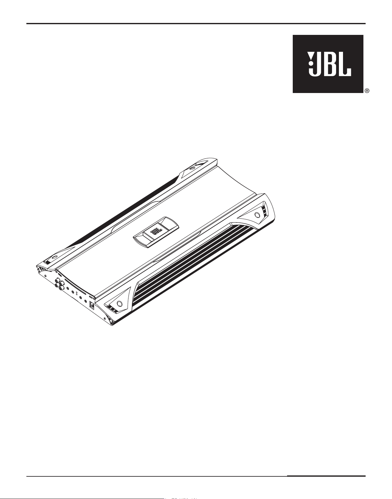
GTO24001
OWNER’S MANUAL
BEDIENUNGS -
ANLEITUNG
MODE D'EMPLOI
MANUAL DE USO
HANDLEIDING
MANUALE UTENTE
ANVÄNDAR -
HANDBOK
BRUGS VEJLEDNING
OMISTAJAN
KÄSIKIRJA
PODRĘCZNIK
UŻYTKOWNIKA
РУКОВОДСТВО
ПОЛЬЗОВАТЕЛЯ
Page 2
Factory Bolt Ring Connector
Ground Wire
Note: Remove any paint
below ring connector.
Star Washer
Śruba fabryczna
Złączka
pierścieniowa
Przewód
uziemiający
Pamiętaj: Usuń farbę
poniżej złączki
pierścieniowej.
Uszczelka
gwiazdowa
4x
1x
1x
2x
1x
1x
10-3/8"
263mm
24-13/16"
2-1/8"
53mm
02
630mm
1
34
5
9A
6
7
AB
B
ABCD
D
8
1"
25mm
C
1-5/8"
40mm
A
8
Page 3

Factory Bolt Ring Connector
Ground Wire
Note: Remove any paint
below ring connector.
Star Washer
ENGLISH
Śruba fabryczna
Złączka
pierścieniowa
Przewód
uziemiający
Pamiętaj: Usuń farbę
poniżej złączki
pierścieniowej.
Uszczelka
gwiazdowa
GTO24001 CAR AUDIO SUBWOOFER AMPLIFIER OWNER’S MANUAL
Installation Warnings and Tips
• Disconnect the negative (–) lead from your vehicle’s
battery.
• At the installation sites, locate and make a note of
all fuel lines, hydraulic brake lines, vacuum lines
and electrical wiring. Use extreme caution when
cutting or drilling in and around these areas.
• Choose a safe mounting location away from
moisture.
• Make sure there is sufficient air circulation at the
mounting location for the amplifier to cool itself.
• Mount the amplifier, using the supplied hardware.
Specifications
• 1700W RMS x 1 channel @ 4 ohms and ≤1% THD + N*
• 2400W RMS x 1 channel @ 2 ohms, 14.4V supply and
<
1% THD + N*
• Frequency response: 20Hz – 330Hz (–3dB)
• Maximum input signal: 6V*
• Maximum sensitivity: 200mV*
• THD + N: 0.5%
• Signal-to-noise ratio: 65dBA
(reference 1W into 4 ohms)*
• Signal-to-noise ratio: 97dBA
(reference rated power into 4 ohms)
* CEA-2006A-compliant
0
Speaker Output Connectors
• Connect the speakers to these terminals,
observing proper polarity. Either + or – terminal
may be used. Minimum total impedance is
2 ohms.
1
Fuse Holder
• Replace fuse only with the same type and rating.
• Mount the included fuse holder within 18" of
the vehicle's battery. Connect one terminal of
the holder to the battery's positive (+) terminal.
Connect the other terminal of the fuse holder
to the amplifier as in 2, below. 0 AWG wire
is recommended. Make sure the wire is not
damaged or pinched during installation. Install
protective grommets when routing wires
through the firewall or other sheet metal.
2
Power Input Connectors
• +12V: Connect to the unused terminal of the
included fuseholder.
• GND: Connect to the vehicle’s chassis. Refer to
the picture below.
• REM: Connect to the “Remote Out” lead from
the source unit or to a source of switched
12V+ (ACC).
3
Aux Output Connectors (RCA)
• Nonfiltered pass-through output. Connect to the
input of an additional amplifier.
4
Input Connectors (RCA)
• Connect to the RCA outputs from the source unit
or signal processor.
5
Input-Level Control
• Used to match the input level of the amplifier
to the output level of the source unit.
• See Bfor the adjustment procedure.
6
Low-Pass Filter Frequency Control
• 12dB/octave low-pass filter,
variable from 32Hz to 320Hz.
• See Cfor the adjustment procedure.
7
DBO (Dynamic Bass Optimization)
Variable Subsonic High-Pass Filter With
Variable Boost (Q)
• For woofers in tuned (vented) enclosures, set
the Frequency control to a value 10Hz below the
enclosure’s resonance (tuned) frequency.
• For woofers in sealed boxes, set the control to
any value you prefer, between 30Hz and 50Hz.
• Set the Boost control according to your
preference, being careful not to apply
enough boost to damage your woofer(s).
A DBO High-Pass Filter Frequency control,
B DBO Boost control provides up to
8
Remote Level Control (RLC) Connector
• Connect the Remote Level Control (RLC) here,
using the supplied RJ-11 cable.
9
Power On LED
• Illuminated when the amplifier is on.
A
Protect LED
• Illuminated under any of the following fault
conditions: battery over/under voltage, short
circuit in speaker wires, amplifier is too hot,
amplifier’s output circuit has failed (DC voltage
is present in the amplifier’s output).
B
Setting Input Level
A Turn Input Level control counterclockwise to
6V (minimum).
B With a dynamic music track playing, turn the
head unit’s volume control to the 3/4 position.
C Turn Input Level control clockwise until the
bass output is proportionate to the output of
the high-frequency speakers, according to
your preference.
D Input level is now adjusted correctly.
C
Setting the Crossover
A Crossover setting for subwoofers.
Note: Acceptable frequency ranges are indicated
in gray.
D
Remote Level Control
The Remote Level Control, if installed, will allow
you to adjust the level of bass while seated in the
listening position.
variable between 10Hz and 100Hz.
See above for appropriate settings.
12dB of boost, slightly above the highpass filter’s frequency. See above for
appropriate settings.
This product is designed for mobile applications and is not
intended for connection to the mains.
A valid serial number is required for warranty coverage.
Features, specifications and appearance are subject to change
without notice.
Page 4

www.jbl.com
Harman Consumer Group, Inc.
250 Crossways Park Drive, Woodbury, NY 11797
www.jbl.com
© 2008 Harman International Industries, Incorporated. All rights reserved.
JBL is a trademark of Harman International Industries, Incorporated,
registered in the United States and/or other countries.
Part No. GTO24001OM 6/08
Declaration of Conformity
We, Harman Consumer Group, Inc.
2, route de Tours
72500 Château du Loir
France
declare in own responsibility that the product described in this owner’s
manual is in compliance with technical standards:
EN 55013:2001+A1:2003
EN 55020:2002+A1:2003
Klaus Lebherz
Harman Consumer Group, Inc.
Château du Loir, France 6/08
 Loading...