

Page 1
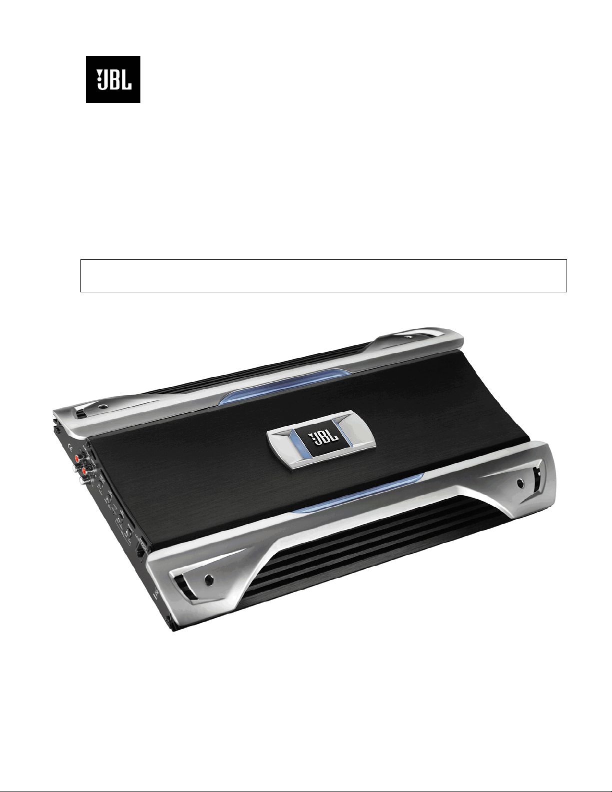
GTO 14001
1 CHANNEL POWER AMPLIFIER
SERVICE MANUAL
Released 2008
Discontinued XXXX
JBL Consumer Products
250 Crossways Park Dr.
Woodbury, New York 11797 Rev0 3/2008
Page 2

1
GTO14001
- CONTENTS -
SPECIFICATIONS ………………………………………..1
PACKING……………………………………………..…....2
CONTROL/INSTALLATION DRAWINGS………………3
CONTROL/INSTALLATION INSTRUCTIONS………....4
BASIC TROUBLESHOOTING……………………………5
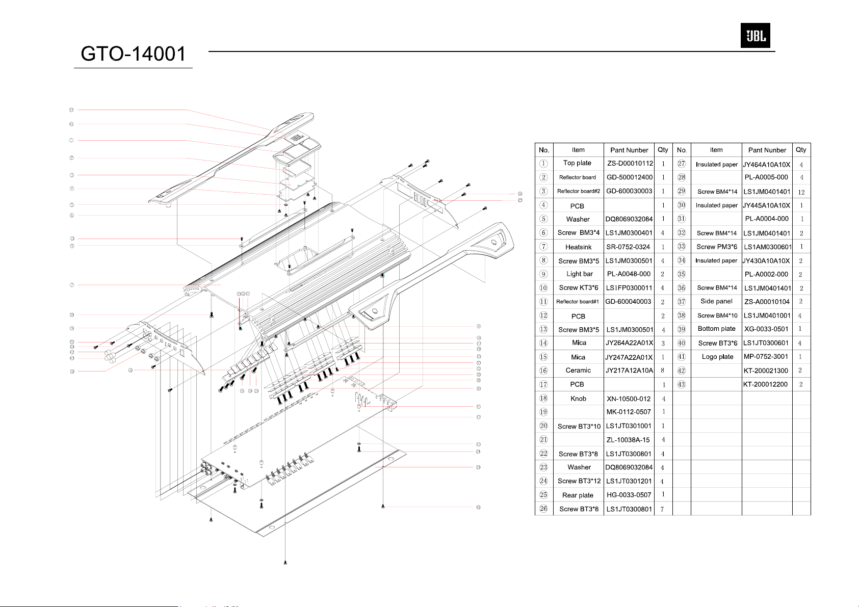
EXPLODED VIEW/PARTS LIST…….….….…………....6
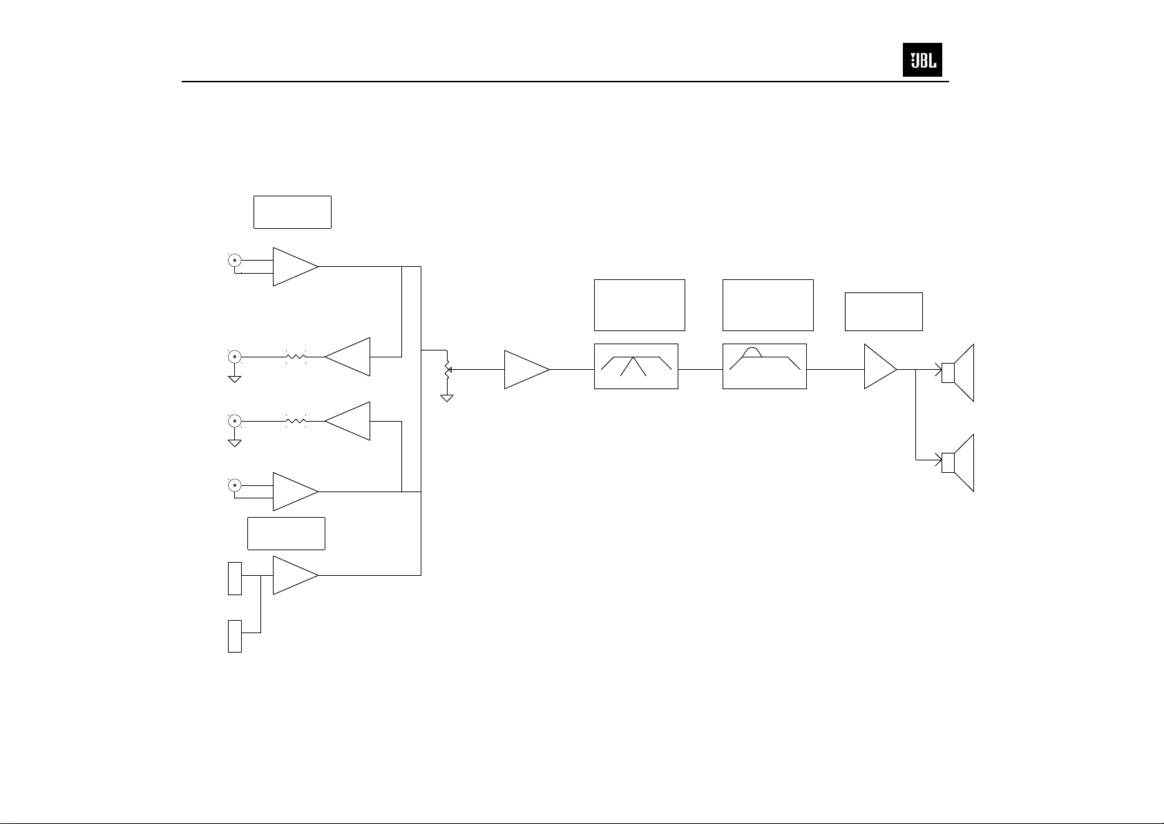
AMPLIFIER BLOCK DIAGRAM…………………….……7
ELECTRICAL PARTS LIST ..……….……….…….…….8
P.C.B. DRAWINGS….………………………..…….……13
IC/TRANSISTOR PINOUTS..………………..….….…..20
SCHEMATICS……………..……………….………..…...21
GTO 14001 Specifications
Output Power: 1200W RMS x 1 channels @ 4 ohms; ≤1% THD + N
(14.4V supply) 1500W RMS x 1 channels @ 2 ohms; ≤1% THD + N
Signal-to-noise ratio: 77dBA (reference 1W into 4 ohms)
108dBA (reference rated power into 4 ohms)
Dynamic power: 1800W @ 2 ohms
Frequency response: 20Hz – 300Hz (–3dB)
THD+N 1KHz LPF=22KHz ≤0.05% (rated power @ 4 ohms)
Input Impedance >20K ohms
Maximum input signal: 6.0V
Maximum sensitivity: 100mV
Bass Boost @ 20-100Hz 0-12dB (±2dB)
DC Offset <30mV
Output regulation: .03dB @ 4 ohms
Idle Current @ 2 ohms 1.8A
Max Current Draw 140A @ 2 ohms
Remote Operating Voltages ON 5V OFF 3.5V
Turn-on delay time 2-3 sec
Circuit Protection Temperature (80±5C), Short circuit
Operating voltage range (8-16V)
Dimensions: 18 9/16 x 10 3/8 x 2 1/8” (470 x 263 x 53mm)
Fuses: (4) x 40A
JBL continually strives to update and improve existing products, as well as create new ones. The specifications and
details in this and related JBL publications are therefore subject to change without notice.
Page 3
2
GTO14001
Page 4
9A
02
8
5 6
34
7
AB
ABCD
A
C
B
18-9/16"
470mm
10-3/8"
263mm
2-1/8"
53mm
8
1-5/8"
40mm
1"
25mm
D
4x
2x
4x
1x
1x
1x
1
3
GTO14001
Page 5
Factory Bolt Ring Connector
G
round Wire
Note: Remove any paint
below ring connector.
Star Washer
4
GTO14001
GTO14001 CAR AUDIO SUBWOOFER AMPLIFIER OWNER’S MANUAL
Installation Warnings and Tips
• Disconnect the negative (–) lead from your vehicle’s
battery.
• At the installation sites, locate and make a note of
all fuel lines, hydraulic brake lines, vacuum lines
and electrical wiring. Use extreme caution when
cutting or drilling in and around these areas.
• Choose a safe mounting location away from moisture.
• Make sure there is sufficient air circulation at the
mounting location for the amplifier to cool itself.
• Mount the amplifier, using the supplied hardware.
Specifications
• 1200W RMS x 1 channel @ 4 ohms and ≤1% THD + N*
• 1500W RMS x 1 channel @ 2 ohms and ≤1% THD + N*
• THD + N: 0.05% (rated power @ 4 ohms)
• Signal-to-noise ratio: 77dBA
(reference 1W into 4 ohms)*
• Signal-to-noise ratio: 108dBA
(reference rated power into 4 ohms)
• Frequency response: 20Hz – 330Hz (–3dB)
• Max power: 1500 watts
* CEA-2006A-compliant
0
Speaker Output Connectors
• Connect the speakers to these terminals,
observing proper polarity. Either + or –
terminal may be used. Minimum total
impedance is 2 ohms.
1
Fuses
• Replace only with the same type and rating.
2
Power Input Connectors
• +12V: Connect to the positive terminal of the
vehicle’s battery. 4 AWG wire is recommended.
Install an appropriate fuse holder and fuse (160A
minimum) within 18 inches of the battery. Make
sure the wire is not damaged or pinched during
installation. Install protective grommets when
routing wires through the firewall or other sheet
metal.
• GND: Connect to the vehicle’s chassis. Refer to
the picture below.
• REM: Connect to the “Remote Out” lead from
the source unit or to a source of switched
12V+ (ACC).
3
Aux Output Connectors (RCA)
• Nonfiltered pass-through output. Connect to the
input of an additional amplifier.
4
Input Connectors (RCA)
• Connect to the RCA outputs from the source unit
or signal processor.
5
Input-Level Control
• Used to match the input level of the amplifier
to the output level of the source unit.
• See Bfor the adjustment procedure.
6
Low-Pass Filter Frequency Control
• 12dB/octave low-pass filter,
variable from 32Hz to 320Hz.
• See Cfor the adjustment procedure.
7
DBO (Dynamic Bass Optimization) Variable
Subsonic High-Pass Filter With Variable Boost (Q)
• For woofers in tuned (vented) enclosures, set
the Frequency control to a value 10Hz below the
enclosure’s resonance (tuned) frequency.
• For woofers in sealed boxes, set the control to
any value you prefer, between 30Hz and 50Hz.
• Set the Boost control according to your
preference, being careful not to apply
enough boost to damage your woofer(s).
A DBO High-Pass Filter Frequency control,
variable between 10Hz and 100Hz. See
above for appropriate settings.
B DBO Boost control provides up to
12dB of boost, slightly above the highpass filter’s frequency. See above for
appropriate settings.
8
Remote Level Control (RLC) Connector
• Connect the Remote Level Control (RLC) here,
using the supplied RJ-11 cable.
9
Power On LED
• Illuminated when the amplifier is on.
A
Protect LED
• Illuminated under any of the following fault
conditions: battery over/under voltage, short
circuit in speaker wires, amplifier is too hot,
amplifier’s output circuit has failed (DC voltage
is present in the amplifier’s output).
B
Setting Input Level
A Turn Input Level control counterclockwise to
6V (minimim).
B With a dynamic music track playing, turn the
head unit’s volume control to the 3/4 position.
C Turn Input Level control clockwise until the
bass output is proportionate to the output of
the high-frequency speakers, according to
your preference.
D Input level is now adjusted correctly.
C
Setting the Crossover
A Crossover setting for subwoofers.
Note: Acceptable frequency ranges are indicated
in gray.
D
Remote Level Control
The Remote Level Control, if installed, will allow
you to adjust the level of bass while seated in the
listening position.
Page 6

5
GTO14001
Amplifier Troubleshooting Guide
1. Status LED on Amplifier not Lit - Head Unit (Source) Turned ON
Verify:
A. Remote turn-on wire from source to amplifier has proper voltage
B. Power (B+) connections at amplifier, terminal blocks, and battery are secure
C. Ground (GND) connections at amplifier and vehicle chassis are secure
D. Battery B+ fuse (if used) is OK
E. Amplifier fuse is OK
F. B+ at battery and B+ at amplifier has proper voltage
2. Status LED’s Lit, No Output from Speakers in Normal Operating Condition
Verify:
A. RCA cables from amplifier to source are securely connected
B. Volume adjustment on amplifier is correctly adjusted
C. Source is ON and playing
3. Engine Noise From Speaker(s)
Turn source OFF, Disconnect RCA cables at amplifier. If noise stops, check equipment & cables leading
to ampli fier.
Verify:
A. RCA cables ar e o f good quality wit h no bre ak a ge to i nternal shiel ds
B. RCA cables from source to amplifier are not run alongside any power cables
4. Amplifier Output Distorted Music
Verify:
A. Source output music to amplifier is not distorted
B. Source output sensitivity is correctly adjusted
5. Amplifier Shuts Down, Green LED’s are Lit - Amplifier is in Thermal Protection Mode
Verify:
A. Amplifier is mounted with adequate air circulation around heatsinks or vents
B. Amplifier is not mounted under carpet or sealed enclosure
C. Speakers meet correct impedance for application (mono or stereo hookup)
6. Amplifier Does Not Turn ON, and Red LED is Lit Amplifier (and not Connected to a Shorted Speaker)
Verify:
A. Speaker crossover (if used) is not defective
Page 7
6
GTO14001
Trans. Clamp
Trans. Clamp
Trans. Clamp
RCA CAP (Red)
RCA CAP (Wht)
Front Plate
Standoff
Page 8
7
GTO14001
BALANCED
INPUT L
1
2
OUTPUT L
OUTPUT R
INPUT R
1
2
INPUT UNIT
OP
GAIN CONTROL
OP
OP
OP
Block Diagram GTO14001
LP FREQ
VARIABLE
32Hz-320Hz/12dB
32 320Hz80 32 320Hz50
OP
BASSBOOST
VARIABLE
0dB-12dB/50Hz
MAIN AMP
AMP
2 ohm/4 ohm
SPEAKER
2 ohm/4 ohm
BALANCED
INPUT UNIT
OP
IMS INPUT
UnRegistered
Page 9

0
8
GTO14001
GTO14001 Electrical Parts List
Qty Part Number Reference Designator
MAIN PCB
Resistors
1 0702-3103-02 R95 Carbon film resistor 1/2W 10KΩ ±5% 12.5MM
5 0702-3220-02 R85 R86 R87 R88 R89 Carbon film resistor 1/2W 22Ω ±5% 12.5MM
2 0702-4123-02 R100 R101 Carbon film resistor 1W 12K ±5% 15mm
2 0705-5470-02 R1 R133 Cement resistor 5W 47Ω ±5%
2 0712-64R7-02 R128 R129 Metal Oxide film resistor 2W 4.7Ω ±5% Horizontal 10MM
2 0712-6221-02 R123 R124 Metal Oxide film resistor 2W 220Ω ±5% Horizontal 10MM
2 0702-3331-02 R93 R94 Carbon film resistor 1/2W 330Ω ±5% 12.5MM
2 0702-3562-02 R91 R92 Carbon film resistor 1/2W 5.6KΩ ±5% 12.5MM
2 0702-3222-02 R68 R71 Carbon film resistor 1/2W 2.2KΩ ±5% 12.5MM
2 0705-5222-02 R125 R126 Cement resistor 5W 2.2KΩ ±5% 13*9*2.5mm 5mm
8 0701-2100-02
24 0701-2101-02
2 0701-2470-02 R20 R78 Resistor SMD 47Ω 1/8W ±5% 0805
2 0701-2221-02 R58 R59 Resistor SMD 220Ω 1/8W ±5% 0805
1 0701-2331-02 R43 Resistor SMD 330Ω 1/8W ±5% 0805
1 0701-2751-02 RX Resistor SMD R0805 750Ω 1/8W ±5%
1 0701-2821-02 R105 Resistor SMD 820Ω 1/8W ±5% 0805
5 0701-2102-02 R44 R48 R49 R50 R121 Resistor SMD 1KΩ 1/8W ±5% 0805
2 0701-2182-02 R115 R12 Resistor SMD 1.8KΩ 1/8W ±5% 0805
9 0701-2222-02
4 0701-2472-02 R39 R40 R41 R127 Resistor SMD 4.7KΩ 1/8W ±5% 0805
1 0701-2113-02 R73 Resistor SMD 11KΩ 1/8W ±5% 0805
1 0701-2332-02 R72 Resistor SMD 3.3KΩ 1/8W ±5% 0805
13 0701-2103-02
2 0701-2153-02 R61 R51 Resistor SMD 15KΩ 1/8W ±5% 0805
1 0701-2203-04 R4 Resistor SMD 20KΩ 1/8W ±5% 0805
5 0701-2223-02 R3 R5 R103 R104 R98 Resistor SMD 22KΩ 1/8W ±5% 0805
13 0701-2473-02
1 0701-2563-02 R106 Resistor SMD 56KΩ
6 0701-2104-02 R34 R35 R54 R55 R56 R116 Resistor SMD 100KΩ 1/8W ±5% 0805
1 0701-2105-02 R96 Resistor SMD 1MΩ 1/8W ±5% 0805
8 0702-0106-03
1 1204-2030-01 VR1 INPUT LEVEL B20K KQ L=15 ±10% in phase=±3dB
1 1201-5030-04 VR2 LP FREQ B50K KQ L=15MM ±10% in phase≤2.5DB
1 1204-2040-02 VR3 HP FREQ B2K/B200K KQ L=15MM ±15% B2K,B200K
1 1204-5041-11 VR4 BOOST B500 KQ L=15 ±10%
1 1201-1031-03 VR5 Variable Resistor TG625MC-B10K
R107 R108 R109 R110 R111 R112
R113 R114
R45 R57 R122 R76 R77 R79 R80 R81
R82 R83 R84 R13 R14 R15 R16 R17
R18 R21 R22 R23 R24 R25 R26 R27
R62 R63 R64 R66 R67 R69 R70 R74
R75
R99 R28 R29 R32 R33 R37 R38 R130
R131 RX200 RX203 RX204 RX2001
R2 R6 R7 R8 R9 R10 R11 R19 R30
R31 R52 R53 R60
R36 R42 R11X R120 R118 R117 R119
R12X
Resistor SMD 10Ω 1/8W ±5% 0805
Resistor SMD 100Ω 1/8W ±5% 0805
Resistor SMD 2.2KΩ 1/8W ±5% 0805
Resistor SMD 10KΩ 1/8W ±5% 0805
Resistor SMD 47KΩ 1/8W ±5% 0805
Resistor 10mΩ ±1% manganese Ф1.5 10.5MM H=16.5MM
Description
1/8W ±5% 0805
Capacitors
2 06D2C3357700 C103 C104 Metal oxide film cap 3.3UF/100V ±20% 105℃ Brown 20.5mm
2 06D2C335C70
3 06D211066109 C86 C45 C46 E-cap 10uF/50V ±20% 5*11 105℃ Black 5MM
6 06D2C1067001 C106 C107 CX103 C98 C99 C81 Metal film cap 10UF/100V ±20% 20MM thickness=10.5MM
7 06D212266010 C1 C2 C3 C4 C5 C6 C7 E-cap 22uF/50V ±20% 5*11 105℃ 5.0MM
3 06D102266000 C22 C34 C52 E-cap 22UF/50V ±10% Φ6.3*11 85℃ NP
4 06D214765000 C90 C91 C43 C84 E-cap 47uF/35V ±20% 5*11 105℃ Black 5MM
3 06D211073001 C67 C78 C83 E-cap 100UF/16V ±20% 6*7 105℃ 5MM
3 06D214775101 C66 C72 C73 E-cap 470UF/35V ±20% Ф8*20MM 105℃ Black
4 06D213387001 C68 C69 C70 C71 E-cap 3300UF/100V 35*30MM ±20%
5 06D212285101 C53 C54 C55 C56 C57 E-cap 2200UF/35V Φ16*26MM ±20% 105℃ Low ESR 7.5MM
1 06D231027000 C109 Ceramic cap 1000pF/100V ±20% 5MM
6 06D231037000 C58 C59 C60 C61 C49 C51 Ceramic cap 0.01uF/100V ±20% 5MM
C92 CX102 Metal oxide film cap 3.3UF/250V ±20% 105℃ Brown 27mm
Page 10

0
g
9
GTO14001
Qty Part Number Reference Designator
Description
MAIN PCB
6 06D231047000 C31 C32 C33 C37 C74 C75 Ceramic cap 0.1uF/100V ±20% 5MM
3 06D3C2247700 C100 C101 C102 Metal film cap 224/100V ±5% Brown 5MM
2 06D374717400 C64 C65 Ta capacitor 470pF/100V ±5% 5.5mm
3 06D1C4747701 C48 C85 C94 C93
1 06D1C105G70
1 06D341547400 C44 MET CAP 154/100V ±5% 5MM
1 06D341847000 C42 MET CAP 184/100V ±5% 5MM
1 06D344737400 C47 MET CAP 473/100V ±5% 5MM
1 06D344747000 C41 MET CAP 474/100V ±5% 5MM
2 06S322206000 C39 C40 Capacitor SMD 22pF/50V 0805 NPO ±5%
5 06S321016000 C10 C11 C12 C13 C38 Capacitor SMD 100pF/50V 0805 NPO ±5%
21 06S121046000
1 06S121244000 C97 Capacitor SMD 0.12UF/25V 0805 X7R ±10%
7 06S124716000 C23 C62 C63 C79 C80 C87 C88 Capacitor SMD 470pF/50V 0805 X7R ±10%
1 06D212285000 C116 E-cap 2200UF/35V φ16*33MM ±20% 105℃
2 06S321006000 C8 C9 Capacitor SMD 10pF/50V 0805 NPO ±5%
Semiconductors
1 04ZL-6A10-00 D17 Diode 6A10 1000V
1 04ZL-4007-03 D39 Diode 1N4007 DO-41
10 04GS-R104-00
8 03D1-TP50-24 Q23 Q24 Q25 Q26 Q27 Q28 Q29 Q30 MOS FET TP50N20P TO-220
8 03T1-3205-02 Q11 Q12 Q13 Q14 Q15 Q16 Q18 Q21 MOS FET IRF3205 110A 50V TO-220
1 2000-0017-00 LED1 LED red light Φ3MM 2P
1 2004-0014-00 LED2 LED Φ3.0MM blue light
2 01FA-7812-04 U7 U8 +12V Pos. Regulator KA7812E TO-220
1 01FA-7912-04 U9 -12V Neg. Regulator KA7912 TO-220
2 2202-1602-05 D26 D27 Bridge rectifier UF1602CT AKA 16/200V TO-220
2 2202-1620-05 D48 D49 Bridge rectifier MUR1620CTA KAD 16A/200V TO-220
19 04PT-4148-01
4 04ZL-2512-00 D32 D33 D34 D35 Rectifying diode SMD MUR120 1A 2512
2 03N1-5551-04 Q9 Q10 Transistor SMD MMBT5551LT1 NPN SOT-23
1 03N1-2222-04 Q22 Transistor SMD BT2222 SOT-23 NPN
5 01JR-4560-08 U1 U2 U3 U4 U5 Dual Op-Amp SMD 4560 SOP-8 JRC
2 04WY-51AV101 DZ1 DZ2 Zener Diode SMD 5.1V DO-213AA 0.5W
1 01TI-L072-09 U6 Dual Op-Amp SMD TL072 SO-8
1 2601-0202-00 LCR1 Optocoupler LCR-0202
CX11 Metal film cap 105/160V ±10% Brown 15MM thickness≤6.5MM
C14 C15 C16 C17 C18 C19 C20 C21
C24 C25 C26 C27 C28 C29 C30 C35
C36 C76 C77 CX2 CX111
D20 D21 D22 D23 D24 D25 D28 D29
D30 D31
D3 D4 D6 D7 D8 D9 D10 D11 D12 D13
D14 D16 DX1 DX2 D1 D2 D5 D15 D18
Metal film cap 474/100V ±10% Brown 7.5mm
Capacitor SMD 0.1uF/50V 0805 X7R ±10%
Diode FR104 1A 400V 52MM
Diode SMD 1N4148 DO-213AA
Miscellaneous
1 1404-0020-04 J1 RCA INPUT, AUX OUT DIP AV4-8.4-38 up-white, down-red Nickel plating
1 1413-0001-00 JK1 Phone jack 6P4C RJ11 vendor model:HPCB-3021-6P4C Black
1 1501-0400-01 CN6 Terminal BTS4-23 Nickel plating, cross screws
1 1501-0300-02 CN3 Terminal BTS3-24 Nickel plating, cross screws
2 1001-3002-10 L8 L9 Power Inductor DIP 30UH/40A ETD49 ф0.1*80*6 13TS
1 1001-1022-10 L10 Common mode choke DIP L1=L2 1MH ф42.5 ф0.5*(24P*4)*2.5TS*2
2 1004-3001-10 L6 L7 Inductor DIP 30UH ф12 ф5 11.5MM ф2*3
2 2901-224C-00 RL1 RL2 Relay DC12V 30A
4 1601-403E-00 F1A-F1D Fuse DIP 40A high temperature durable
1 1380-0209-00 SW1 Temperature switch
1 1401-0002-04 for F1 Fuse holder DIP 4PIN
1 3000-1400-05 L4 HF Transformer
1 3000-1400-06 L5 HF Transformer φ49 4:9 F1=F2=φ0.8*16 4TS S1=S2=φ0.8*10 9TS
1 1001-3500-10 L10 Inductor DIP ф47 35UH*2 ф0.3*40*22TS ±30%
2 3501-0029-00 L11 L12 Inductor K4D RH 7.8*15*3 L=1.8UH (Φ2.0*70MM*0.5TS)±10%
1 1502-0209-00 CN1 Socket DIP PITCH 2.54MM 2PIN bending 90°
2 1003-1003-08 R46 R47 Inductor SMD 0805 10UH 0.5A
DIP, operatin
φ49 4:9:7:6 F1=F2=φ0.8*16 4TS S1=S2=φ0.8*10 9TS
S3=S4=φ1.0*1 7TS S5=S6=φ1.0*1 6TS
temp 80℃±5℃ TO-220, 2pins
Page 11

10
GTO14001
Qty Part Number Reference Designator
Description
CONTROL PCB
Resistors
1 0701-2104-02 R64 Resistor SMD 100KΩ 1/8W ±5% 0805
4 0701-2103-02 R3 R33 R30 R31 Resistor SMD 10KΩ 1/8W ±5% 0805
4 0701-2100-02 R117 R118 R193 R198 Resistor SMD 10Ω 1/8W ±5% 0805
2 0701-2102-02 R55 R58 Resistor SMD 1KΩ 1/8W ±5% 0805
2 0701-2222-02 R105 R106 Resistor SMD 2.2KΩ 1/8W ±5% 0805
1 0701-2153-02 R2 Resistor SMD 15KΩ 1/8W ±5% 0805
5 0701-2472-02 R40 R41 R42 R43 R44 Resistor SMD 4.7KΩ 1/8W ±5% 0805
1 0701-2821-02 R45 Resistor SMD 820Ω 1/8W ±5% 0805
2 0701-2681-02 R116 R199 Resistor SMD 680Ω 1/8W ±5% 0805
1 0701-2152-02 R56 Resistor SMD 1.5KΩ 1/8W ±5% 0805
3 0701-2101-02 R49 R191 R192 Resistor SMD 100Ω 1/8W ±5% 0805
1 0701-2303-03 R29 Resistor SMD 30K 1/8W ±1% 0805
1 0701-2221-02 R113 Resistor SMD 220Ω 1/8W ±5% 0805
1 0701-2331-02 R48 Resistor SMD 330Ω 1/8W ±5% 0805
1 0701-2473-02 R57 Resistor SMD 47KΩ 1/8W ±5% 0805
Capacitors
1 06S2447644CD C93 C94 Ta Capacitor SMD 47uF/25V CASE-D ±20% Yellow
1 06S321026000 C100 Capacitor SMD 1000pF/50V 0805 NPO ±5%
2 06S321016000 C61 C62 Capacitor SMD 100pF/50V 0805 NPO ±5%
8 06S121046000 C57 C59 C60 C63 C75 C77 C91 C92 Capacitor SMD 0.1uF/50V 0805 X7R ±10%
2 06S132253000 C104 E1 Capacitor SMD 2.2uF/16V 1206 X7R ±10%
1 06S123326000 C64 Capacitor SMD 332/50V ±10% X7R 0805
1 06S2447634CC C43 Ta Capacitor SMD 47uF/16V CASE-C ±20% Yellow
1 06S2410724CC C58 Ta Capacitor SMD 100UF/10V CASE-C ±20% Yellow
2 06S124727000 C55 C56 Capacitor SMD 472/100V 0805 X7R ±10%
NOTE THERE ARE TWO IDENTICAL CONTROL PCB'S IN THE GTO14001
Semiconductors
1 2601-4N35-00 U17 Optocoupler 4N35 DIP6
1 0100-C081-08 U8 Single Op-Amp TLC081 SOP-8
1 01LM-M555-08 U7 Timer SMD LM555 SOP-8
1 0100-74AH-00 U16 Inverter 74AHC1G04 SOT-235
1 0100-2010-00 U10 High/Low side Driver IR2010S SOL-16
1 03P1-5401-04 Q30 Transistor SMD MMBT5401LT1 PNP SOT-23
1 01TC-WH04-00 U9 Triple Inverter TC7WH04F
1 04ZL-2512-00 D8 Zener Diode SMD MUR120 1A 2512
1 01LM-M311-08 U11 Single Comparator SMD LM311 SOP-8
5 04PT-4148-01 D2 D3 D4 D7 D49 Diode SMD 1N4148 DO-213AA
1 04WY-51AV101 DZ1 Zener Diode SMD 5.1V DO-213AA 0.5W
Miscellaneous
1 1505-1009-04 CN6 Pin DIP PITCH 2.54mm 10PIN*2, bending 90°
PWM PCB
Resistors
1 0701-2221-02 2R65 Resistor SMD 220Ω 1/8W ±5% 0805
3 0701-2102-02 2R5 2R155 2R156 Resistor SMD 1KΩ 1/8W ±5% 0805
3 0701-2202-02 2R33 2R138 2R146 Resistor SMD R0805 2KΩ 1/8W ±5%
1 0701-2222-02 2R132 Resistor SMD 2.2KΩ 1/8W ±5% 0805
1 0701-2432-02 2R102 Resistor SMD 4.3KΩ 1/8W ±5% 0805
2 0701-2472-02 2R46 2R147 Resistor SMD 4.7KΩ 1/8W ±5% 0805
1 0701-2512-02 2R200 Resistor SMD 5.1KΩ 1/8W ±5% 0805
9 0701-2103-02
1 0701-2113-02 2R171 Resistor SMD 11KΩ 1/8W ±5% 0805
1 0701-2123-02 2R35 Resistor SMD 12KΩ 1/8W ±5% 0805
2 0701-2203-04 2R104 2R175 Resistor SMD 20KΩ 1/8W ±5% 0805
2R1 2R34 2R36 2R78 2R99 2R137
2R148 2R152 2R149
Resistor SMD 10KΩ 1/8W ±5% 0805
Page 12

2R3 2R4 2R19 2R20 2R44 2R97
11
GTO14001
Qty Part Number Reference Designator
Description
PWM PCB
1 0701-2333-02 2R98 Resistor SMD 33KΩ 1/8W ±5% 0805
7 0701-2473-02
1 0701-2623-02 2R2 Resistor SMD 62KΩ 1/8W ±5% 0805
1 0701-2753-02 2R103 Resistor SMD 75K ±5% 1/8W 0805
1 0701-2104-02 2R154 Resistor SMD 100KΩ 1/8W ±5% 0805
Capacitors
1 06S121026000 2C143 Capacitor SMD 1000pF/50V 0805 X7R ±10%
12 06S121047000
2 06D212264103 2C87 2C88 E-cap 220uF/25V ±20% 8*12 105℃ Black, 5MM
1 06D211074100 2C2 E-cap 100uF/25V ±20% 6.3*11 105℃ Black, 5MM
Semiconductors
2 03P1-1023-01 2Q19 2Q20 Transistor A1023 TO-92 PNP
1 03P1-B649-07 2Q17 Transistor 2SB649A 1.5A 180V 20W PNP TO-126
15 04PT-4148-01
12 03N1-5551-04
1 03P1-5401-04 2Q32 Transistor SMD MMBT5401LT1 PNP SOT-23
1 01TI-L494-09 2U18 PWM IC SMD TL494C SO-16
2C1 2C22 2C34 2C79 2C80 2C81
2C82 2C84 2C89 2C117 2C132 2C151
2D1 2D2 2D36 2D40 2D41 2D42 2D43
2D45 2D46 2D47 2D5 2D15 2D18
2D19 2D37
2Q1 2Q2 2Q3 2Q4 2Q5 2Q6 2Q7 2Q8
2Q33 2Q37 2Q38 2Q39
Resistor SMD 47KΩ 1/8W ±5% 0805
Capacitor SMD 104/100V 0805 X7R ±10%
Diode SMD 1N4148 DO-213AA
Transistor SMD MMBT5551LT1 NPN SOT-23
Miscellaneous
2 1506-0805-00 2CN1 Pin 8PIN*2, Bending 90℃, 2.5MM
1 1003-1010-08 2L1 Inductor SMD 100MH 100MHZ 4A
LED PCB
8 0701-3102-02 R1 R2 R3 R4 R5 R6 R7 R8 Resistor SMD 1KΩ 1/4W ±5% 1206
2 2100-0067-02 FFC
1 2100-0068-02 FFC
8 2005-0009-00
1 06S121046000 C1 SMD cap SMD 0.1uF/50V 0805 X7R ±10%
MISCELLANEOUS/MECHANICAL
1 SR-0752-0324 Heatsink
2 PL-A0048-000 Light bar 203.4*10.5*6.5MM light grey PC
1 GD-500012400 Reflector board 57.4*38.0*5.8MM Light grey PC
1 ZS-D00010112 Logo house 110.0*49.80*9.0MM Alum. With chromeplating
2 ZS-A00010104 Side panel 470.0*51.94MM Alum. With chromeplating
1 MK-0112-0507 Front plate 240.6*50.3*1.2MM 1.2MM Black with silkscreen
1 HG-0033-0507 Rear plate 240.6*50.3*1.2MM 1.2MMBlack with silkscreen
4 LS1JM0300401
4 LS1JM0300501
4 LS1FP0300011
4 LS1JM0401011
11 LS1JT0300801
4 LS1JT0300601
LED1 LED2 LED3 LED4 LED5 LED6
LED7 LED8
Indicator DIP LED 2*3*4mm
Screw, BM3*4Black zinc
plating
Screw, BM3*5Black zinc
plating
Screw, KT3*6Black zinc
plating
Screw, BM4*10Black zinc
plating
Screw, BT3*8Black zinc
plating
Screw, BT3*6Black zinc
plating
2PIN UL1007 AWG26 L=70mm ends with tin 5mm,
durable by 105℃
2PIN UL1007 AWG26 L=210mm one end with 2.54
terminal, one end with tin 5mm, durable by 105℃
261.0*51.4*440.5MM Extrusion Alum. With Brushed
metal surface
Screw the temperture switch to heatsink
For side LED board
For light bar
For side panel
For front/rear plate and connector
For bottom plate
Page 13

12
GTO14001
Qty Part Number Reference Designator
Description
MISCELLANEOUS/MECHANICAL
16 LS1JM0401401
4 LS1JT0301201
1 LS1JT0301001
4 ZL-10038A-15 Standoff φ4.9*φ7.2*7.0mm Nylon 66
5 DQ8069032084 Washer Φ6.9*Φ3.2*0.8MM M3, For Logo house PCB board
1 JY264A22A01X MICA 64*22*0.1MM Ф4.5MM 16.5MM 7MM
1 PL-E0011-150 Light diffusion paper 64.0*41.0*0.1MM two sides with glud
1 XG-0033-0501 Bottom plate 234.0*439.2*1.2MM 1.2MM black painting
1 JY247A22A01X MICA 47*22*0.1MM Φ4.5mm 16.5mm 7mm
4 LS1AA0404501 Screw PA4*45 black Zinc plating
1 MP-O752-3001 Logo plate
2 GD-600030003 Reflector board 1 175.0*6.0*2.0MM PC Clear silkscreen
1 GD-600040003 Reflector board 2 64.0*41.0*2.0MM PC Clear silkscreen
16 JY217A12A10A Pottery 17*12*1.0mm White
2 LS1FJ0200801 Screw KA2*8 black Zinc
2 LS1CA0301501 Screw TA3*15 black Zinc
1 LS1AM0300601 Screw PM3*6 SWC black Zinc, temperature switch
4 XN-10500-012 Knob, Controls ABS-757 black Ф10.5*9MM with white arrow
4 JY442A24A05X Insulated paper ф42.0*ф24.0*0.5MM red one sided glued,inductor
1 24T1-012800B J2 Jumper 128.00*21.00*1.50MM, yellow copper
3 PL-G0003-000 J3 J4 J5 HA604 Jumper 95*20.7*1.5mm T=1.5mm
2 PL-E0017-150 Light diffusion paper 175.0*6.5*0.1 ends with 3m
1 JY432A13A10X Insulated paper 32.0*13.0*1.0 red with one sided glued,For E-cap
1 JY440A20A05X Insulated paper 40.0*20.0*0.5 red with one sided 3M, For E-cap
2 PL-A0051-000 Transistor Clamp 14.0*7.0*30.0 with red isulated paper (30.0*10.0*1.0)
4 PL-A0054-000 Transistor Clamp 14.0*7.0*64.0 with red isulated paper (64.0*10.0*1.0)
1 PL-A0055-000 Transistor Clamp 14.0*7.0*45.0 with red isulated paper (45.0*10.0*1.0)
4 LS1CM0300501 Insulated paper TM3*5 black Zinc
Screw, BM4*14Black zinc
plating
Screw, BT3*12Black zinc
plating
Screw, BT3*10Black zinc
plating
For power transistor
For PCB board
For RCA terminal
43.73*35.94*2.0MM Alum. Plate with stamped JBL
logo, brushed mental surface on the plate, diamond cut
on JBL logo. With one side glue. Durable by 95 ~ -35 ℃
Page 14

13
GTO14001
Page 15

14
GTO14001
Page 16

15
GTO14001
Page 17

16
GTO14001
Page 18

17
GTO14001
Page 19

18
GTO14001
Page 20

19
GTO14001
Page 21

20
GTO14001
Page 22

1110987654321
21
12
GTO14001
C44
154
R73
11K
46
C47
473
+VCC
C45
10U/50V
CX2
104
CX111
104
RELOU
RL1
1 2
12V/30A
C107
4 5
C106
10U/100V
4 5
CX103
1 2
-12V
R23
C29
100R
104
48
U4A
2
1
3
+
JRC4560
R24
C30
100R
104
+12V
SIG1
R34
100K
SIG2
R35
100K
+12VD39
4004
L12
2UH
+SP
RL2
12V/30A
3
R133
47R/5W
R1
47R/5W
3
1 2
1 2
+12VRELOU
C81
10U/100V
-SP
RX200
10K
SP
CN6
1
2
SPEAKER OUT
3
4
CN4
C37
104
RX2001
10K
L11
2UH
D
C
B
A
+12V
32
R61
15K
R50
1K
100R
R122
VR4A
B500R
1 3
R115
1.8K
D10
IN4148
CX102
3.3U/250V
IN4148
D11
IN4148
D14
D16
LCR1
LCR0202
R116
100K
R110
10R
R109
10R
50N20
R33
10K
4148
50N20
Q25
D1
R45
100R
Q26
0.1
R114
10R
4
A
K
1
LIMITER
0.1
R113
10R
Q30
50N20
Q29
50N20
0.1
Q10
5551
R12
1.8K
7
+VCC
R11X
R117
0.1
0.1
D
C12
R10
47K
F1B
40A
C48
474
4.5MH/60A
R74
2.2K
R75
2.2K
100P
R7
47K
U1A
2
3
C10
100P
R11
47K
C15
104
6
5
C11
100P
C14
104
L3
6A10
R81
100R
Q15
3205
Q16
3205
R82
100R
R28
1
10K
JRC4560
C13
100P
-12V
R13
100R
R29
7
U1B
10K
JRC4560
8 4
R14
100R
+12V
W2200U/35V
P+12V
C53
W2200U/35V
3205
R83
100R
Q18
3205
Q21
R84
100R
W2200U/35V
C54
R79
100R
Q13
3205
Q14
3205
R80
100R
D17
C31
104
C49
222
R76
100R
Q11
3205
Q12
3205
R77
100R
W2200U/35V
C55
R89
22R/ 1/2W
C60
103
C61
103
R88
22R/ 1/2W
2
3
R39
4.7K
W2200U/35V
C56
22R/ 1/2W
103
22R/ 1/2W
C23
471
R40
4.7K
U2A
JRC4560
C57
R86
C58
C59
103
R85
1
3
2
4
F1=F2=Φ0.8*16 4TS
S1=S2=Φ0.8*10 8TS
1
1
3
2
4
F1=F2=Φ0.8*16 4TS
S1=S2=Φ0.8*10 8TS
S3=S4=Φ1*1 6TS
S5=S6=Φ1*1 7TS
Φ49
10K1/2W
R15
100R
R95
C22
22U/50V
VR1A
B20K
Φ49
C5
2
RADIO
22U/50V
1 3
R43
330R
D20
FR104
C63
471
R25
100R
FR104
13
12
11
C62 471
14
5
10
6
7
8
9
13
12
11
14
5
10
L5
T54
6
7
8
9
FR104
D21
22R/ 1/2W
D22
R87
2 1
J2
95MM
R26
100R
C66
470/35V
L4
T54
C109
102/100V
47K
R31
R8
C3
47K
22U/50V
R3
C8
22K
J1A
RCA-4CH
1
1
RCA IN
C
CN2
CN-9P-180
B
A
2
2
3
3
4
J1B
RCA-4CH
4
R5
22K
C52
22U/50V
CN3
3
+12V
REM
2
PGND
1
POWER
1
2
3
P+12V
4
5
6
7
8
9
+12V
10
11
DIAG
12
RELOU
13
DCPR
14
4N35
15
16
SP
LED1
PROTECT
+12V.D
PRLED
POLED
LED2
POWER
C1
22U/50V
C4
22U/50V
C2
22U/50V
R46
10UH
1 2
3 4
F1C
5 6
40A
3
7 8
2
1
R59
220R
R2
47K
C34
22U/50V
F1A
40A
F1D
40A
REM
SW1
JUC-31F/80C
10P
R6
47K
R9
47K
C9
10P
R19
47K
C39
R30
47K
FR104
FR104
22p
R52
47K
2
3
U3A
JRC4560
C40
22p
R53
47K
C26
104
6
5
8 4
R18
100R
+12V
U7 L7812
1
Vin
C16
104
-VCC
D28
D29
D30
FR104
D31
FR104
D26
MUR1620CT
1 2
D27
MUR1620CT
1 2
MUR1620CT
P+12V
1
R21
100R
7
C27
104
D23
FR104
Vout
GND
2
L6
30UH
L7
30UH
D48
MUR1620CT
D49
2 1
J3
95MM
R48 1k
R49 1k
U3B
JRC4560
100U/16V
C18
104
C17
104
-12V
C67
4700U/80V
CX11
104/100V
4700U/80V
3
22U/50V
C68
C70
C6
22U/50V
C7
+12V.BIAS
C73
470U/35V
C72
470U/35V
4700U/80V
R54
100K
R55
100K
C19
104
FR104
1
1
C69
C71
4700U/80V
D24
U8 L7812
Vin
2
2
Vin
U9 L7912
D25
FR104
C32
104
C74
104
C75
C33
104
104
J5
21
95MM
C35
104
Vout
GND
Vout
GND
5
7
R4
20K
100U/16V
100U/16V
R91
5.6K
R92
5.6K
COM1
RCA-4CH
R47
10UH
R63
2.2K
D7
IN4148
C83
C78
J1C
5
6
8
RCA OUT
6
8
7
J1D
RCA-4CH
R64
2.2K
Q22
MMBT2222
3
C21
104
C85
474
C20
104
3
+VCC
-VCC
DX2
IN4148
SD1
SD2
DX1
IN4148
C86
10U/25V
+12V
R93
+5V
330R
C77
DZ1
104
5.1V
DZ2
5.1V
-12V
R94
330R
C90
47U/25V
C91
47U/25V
C76
104
-5V
CN4
20PIN
MODL
4N35
20
19
18
17
SD1
16
+12V.BIAS
15
14
13
12
11
10
9
8
+12V.D
7
+5V
6
-5V
5
PWM1
4
3
2
1
SIG1
SIG1
CN5
20PIN
SIG2
4N351
20
19
18
17
16
15
14
13
12
11
10
9
8
7
6
5
4
3
2
1
SD2
+12V.BIAS
+12V.D
+5V
-5V
PWM2
SIG2
4148
RX203
10K
D4
RX204
10K
JK1
1
1
2
2
3
3
4
+12V
R41 4.7K
RJ-11
R60
D3
R32
47K
4148
C43
10K
47U/16V
+VIN1
VR3A
B2K
+VIN2
C41
474
2
R100
12K/1W
R105
820
12K/1W
C42
184
R106
56K
13
5
HO1
R67
2.2K
OU1
COM1
R66
D8
2.2K
IN4148
LO1
IN4148
R101
COM2
R69
2.2K
LO2
R57
100R
4N352
D6
4148
4N35
4N35
DBO
5
6
46
VR3B
B200K
D9
IN4148
HO2
D12
OU2
D13
IN4148
R58
220R
Q9
5551
U4B
JRC4560
R107
10R
Q24
50N20
50N20
R108
10R
R70
2.2K
+
-
Q23
R111
10R
2
BASSSUB SONIC
BOOSTER
Q28
50N20
Q27
50N20
R112
10R
+12V
7
C92
3.3U/250V
IN4148
RADIO
U6B
JRC4560
C97
124
D32
MUR120
R118
R36
0.1
R120
R119
-VCC
-
+
C93
474/100V
D35
MUR120
D34
MUR120
R12X
R42
0.1
0.1
-VCC
R44
1K
C84
47U/25V
C94
474/100V
MUR120
R123
220
+VCC
C24
104
R51
18K
6
5
C25
104
6
5
R62
2.2K
D33
R125
2.2K/5W
PWM1
R124
220
R96
1M
C36
104
95MM
J4
PWM1
C64
471
R126
2.2K/5W
PWM2
8 4
U5A
JRC4560
3
2
C38
100P
JRC4560
+12V
D5
4148
C28
104
R127
4.7K
21
PWM2
C65
471
U2B
L9
40
R16
100R
R17
100R
4148
D2
+
-
-12V
C99
10U/100V
-12V
LPF FREQ
R72
VR2A
B50K
1 3
2
VR5A
R104
22k
R121
3
1K
2
7
U5B
JRC4560
VR2B
B50K
5
10K
13
2
D15
D18
4148
4148
R103
R98
22K
22K
R78
47R
R20
47R
C46
10U/50V
10U/100V
L10
20
C102
224
10U/100V
3.3K
Rx
7
750
R56
100K
+12V
10K
R99
+12V
R22
100R
1
4 8
C79
471
R27
100R
L8
40
C98
10U/100V
C101
224
R37
10K
DCPR
C104
3.3U/100V
R129
4.7R/2W
+
1
-
JRC4560
4 8
U6A
-12V
C80 471
R38 10K
6
-
5
+
C103
3.3U/100V
C100
R68
224
2.2K
R128
4.7R/2W
C51
222
R130
10K
R131
10K
R71
2.2K
ECN NO
1 2 3 4 5 6 7 8 9 10 11 12
DESCRIPTON
DATAAPPROVED
PART NAME:
PRODUCT MODE:
GTO14001
SCALE: 1:1
UNIT: MM
SIZE: A3
REV: 1.0
DRAWN BY:
CHECKED BY:
APPROVED BY:
DW GNO:
PART NO:
DATA:
DATA:
DATA:
Page 23

54321
22
6
GTO14001
D
2L1
REM
10R/100MHZ
2R1
10K
2R19
47K
2R132
2.2K
2Q17
2Q33
B649
5551
2R102
4.3K
+12V.D
C
2C79
47K
104
2R20
2R138
2R34
10K
2K
2Q32
5401
2R171
11K
OVP
104
2C81
2C80
104
2R149
10K
2R35
12K
2C82
16
+
+1-2FED3DT4C5R6GND7OP1
2R46
4.7K
104
2C22
104
UVP
2C1
104
2C84
104
15
-
14
REF
2D40
4148
2D5
IN4148
2D41
4148
2D36
4148
2D15
IN4148
2D37
IN4148
2R36
10K
2R2
62K
TL494CN
2C151
C104
2C117
CON13VCC
104
2R154
100K
12
2U18TL494
2C143
P+12V
102
11
OP2
2R175
20K
9
E210E1
8
2R155
1K
2R156
1K
P+12V
2C132
104
2D18
IN4148
IN4148
2D19
DIAG
2Q19
A1023
2Q20
A1023
PRLED
DCPR
+12V
P+12V
REM
POLED
4N35
+12V.D
+SP
SW
QB
QA
DIAG
D
2CN1
1
2
3
4
5
6
7
8
9
10
11
12
13
14
15
16
CN14
C
2D43
4148
4N35
2D45
4148
2R78
10K
2R146
2R152
10K
2D2
4148
2K
2D47
4148
2D42
4148
POLED
+12V
2R200
5.1K
2Q38
5551
10K
2R99
2R137
10K
2D46
4148
RELOU
2D1
4148
B
A
1 2 3 4 5 6
2R148
10K
+12V.D
PRLED
2Q1
5551
2Q4
5551
2R33
2K
2R65
220R
2Q3
5551
220U/25V
2C34
104
+12V
+SP
2R97
2R4
47K
47K
2C87
2R98
33K
2R44
47K
2R3
47K
2C2
100U/25V
+SP
2Q5
5551
2Q39
5551
2R5
1K
2C89
104
2Q6
5551
2C88
220U/25V
2Q37
5551
2R103
75K
2R145
47K
2R104
20K
2R147
4.7K
SW
ECN NO
RELOU
2Q2
5551
DESCRIPTON
2Q7
5551
2Q8
5551
DATAAPPROVED
PART NAME:
POWER
PRODUCT MODE:
SYSTEM ONE
SCALE: 1:1
UNIT: MM
SIZE: A4
REV: 2.0
DRAWN BY:
CHECKED BY:
APPROVED BY:
DW GNO:
PART NO:
DATA:
DATA:
DATA:
B
A
Page 24

23
GTO14001
D
C
B
NOTE THERE ARE TWO IDENTICAL CONTROL PCB'S IN THE GTO14001
R64
100K
SIG
R40
4.7K
C75
104
PWM
R2
15K
-5V
C55 472
1
2
3
R191
100R
U8
081C
SD
C100
102
R55
1K
R48
330R
+5V
R192
100R
8
C57
104
C56
472
R30
10K
7
6
54
C104
2.2U/16V
COM
D4
IN4148
R31
10K
1
U16
2
AO4G
3 4
C77
104
5
6
4
+12VOU
+5V
U17
4N35
1
2
3
R44
4.7K
NC
R49
100R
NC
U9
7W04
Q30
5401
R41
4.7K
1
R113
25
220R
3
C59
104
8
7
6
54
R105
2.2K
D2
IN4148
D7
IN4148
COM+12V.D
+5V.BLAS
C60
104
R106
2.2K
D3
IN4148
47U/10V
C61
100P
C43
DZ1
5.1V
C62
100P
R29
30K
C58
100U/10V
R3
10K
R199
680R
R116
680R
E1
2.2U/16V
10
11
12
13
14
15
16
D49
IN4148
3
7
6
+12V.BIAS
U10
2010
+5V.BLAS
8
Q
VCC
DIS
THR
GND
1
C63
104
R118
10R
TRIG
CVolt
U7
555
R42
4.7K
COM
R33
10K
R45
820R
D8
MUR120
R43
4.7K
C93
4.7U/50V
C91
104
COM
R56
1.5K
R57
47.5K
C92
104
C94
4.7U/50V
8
7
U11
LM311
2
1
C64
332
R193
10R
R117
10R
R198
10R
89
7
6
5
4
3
2
1
4
R
2
5
54321
HOOU
+5V
SD
SIG
CN6
CN-20P-180
-5V
20
19
18
17
16
15
14
13
12
11
10
9
8
7
6
5
4
3
2
1
HO
LOOU
-VCC
COM
SD
+12V.BIAS
LO
+12VOU
6
54
R58
3
1K
PWM
SIG
+12V.D
PWM
+12VOU
6
D
C
B
-VCC
A
ECN NO
1 2 3 4 56
DESCRIPTON
DATAAPPROVED
GTO14001
SCALE: 1:1
UNIT: MM
SIZE: A4
REV: 1.0
DRAWN BY:
CHECKED BY:
APPROVED BY:
DW GNO:
PART NO:
DATA:
DATA:
DATA:
A
 Loading...