

Page 1
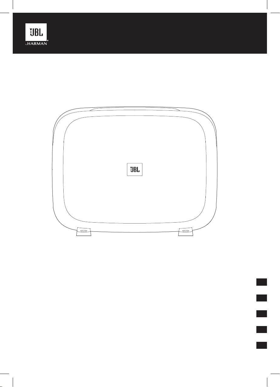
JBL FUSE
JBL Fuse Installation Guide
Guide d'installation de la JBL Fuse
Guía de instalación de JBL Fuse
JBL Fuse Installationsanleitung
Manuale d'installazione JBL Fuse
EN
FR
ES
DE
IT
Page 2

Page 3
EN
JBL FUSE
THANK YOU FOR YOUR PURCHASE . . .
Your JBL product has been designed to provide you with the performance and ease of operation you would expect from
JBL.
ABOUT THE MANUAL
This manual describes general installation guidelines. However, please note that proper installation of mobile audio
components requires qualified experience. If you do not have the knowledge and tools to successfully perform this
installation, we strongly recommend consulting an authorized JBL dealer about your installation options. Keep all instructions
and sales receipts for reference.
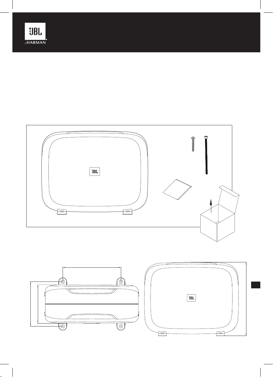
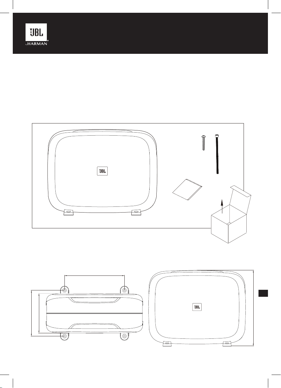
4X
8X
1X
DIMENSIONS
6.5 in. (165.1mm)
5-5/8 in. (142.5mm)
1X
8.5 in. (215.9mm)
10-3/4 in. (273.0mm)
1
Page 4
EN
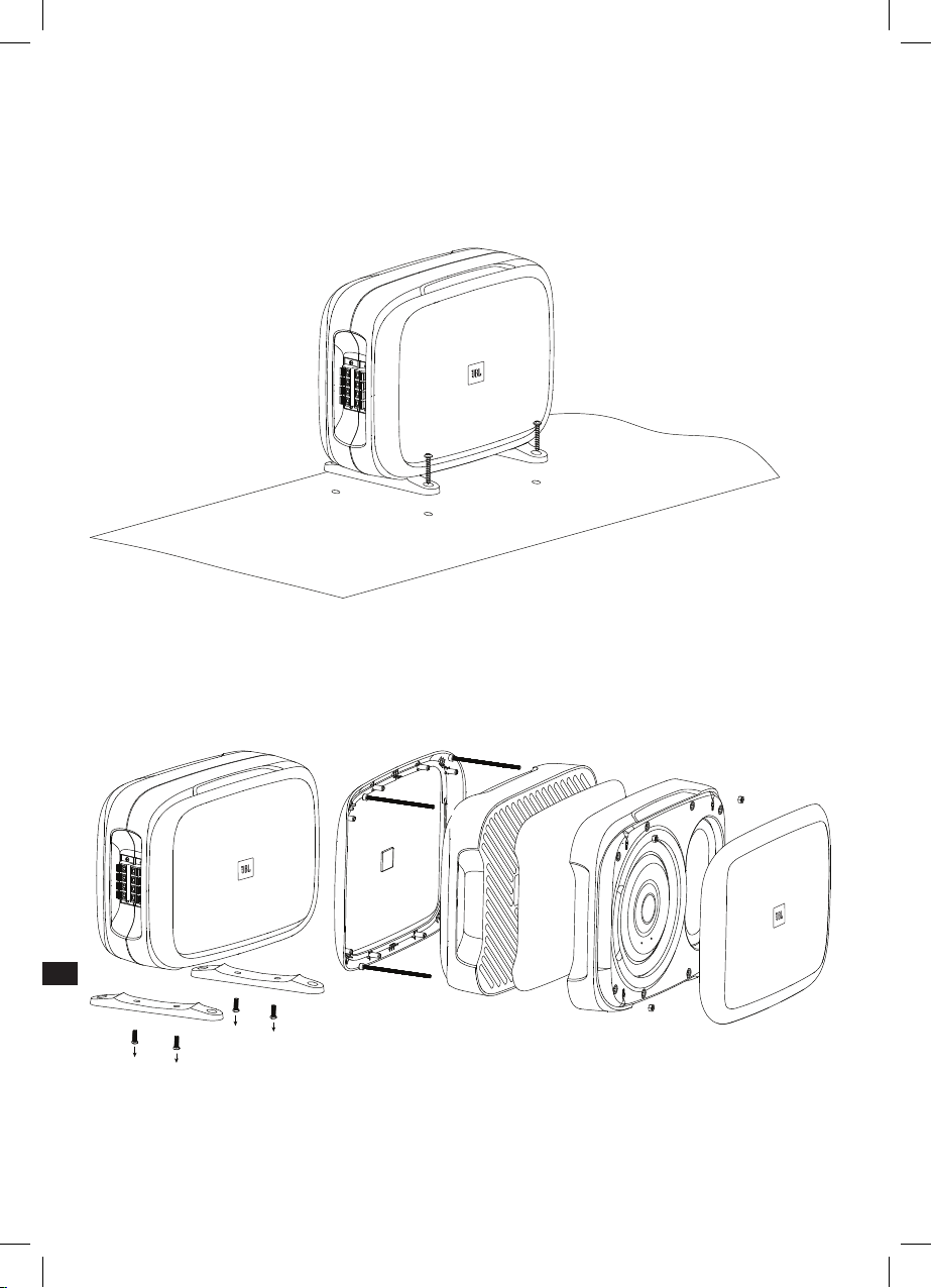
MOUNTING THE FUSE
Vertical mounting
1. Select a suitable location in the cargo area or trunk.
2. Use the included screws to secure the feet to the mounting surface.
NOTE: Before drilling pilot holes for the mounting screws, check beneath the mounting surface to ensure you will not
puncture fuel lines, brake lines, or any vehicle wires.
Separating the twin enclosures
1. Remove four screws securing the mounting feet; remove mounting feet.
2. Remove speaker grilles.
3. Remove four (4) bolts securing twin enclosures.
4. Separate twin enclosures.
Floor mounting
1. Select a suitable location, such as under a seat.
2. Use the included bolts to secure to the mounting surface.
3. Replace speaker grilles.
2
Page 5
EN
NOTE: Before drilling pilot holes for the mounting screws, check beneath the mounting surface to ensure you will not
puncture fuel lines, brake lines, or any vehicle wires.
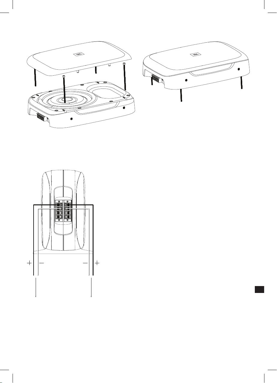
Wiring the subwoofers
Connect the speaker outputs of your power amplifier to the spring terminals of the Fuse enclosures using 14-gauge speaker
wire (not included).
NOTE: Be sure to observe proper wire polarity.
To power amplifier
3
Page 6

EN
SPECIFICATIONS
Continuous power handling 200 watts RMS
Peak power handling 600 watts
Frequency response 30 Hz – 200 Hz
Nominal impedance 2 ohms (parallel connection)
Sensitivity @ 2.83V 90 dB
4 ohms separating twin enclosure
HARMAN International Industries,
Incorporated 8500 Balboa Boulevard,
Northridge, CA 91329 USA
www.jbl.com
© 2019 HARMAN International Industries, Incorporated. All rights reserved.
JBL is a trademark of HARMAN International Industries, Incorporated,
registered in the United States and/or other countries. Features, specifications
and appearance are subject to change without notice.
4
Page 7
FR
JBL FUSE
MERCI POUR VOTRE ACHAT. . .
Votre produit JBL a été conçu pour vous offrir les performances et la facilité d'utilisation que vous attendez de notre part.
PRÉSENTATION DU MANUEL
Ce manuel contient les directives d'installation générales. Cependant, veuillez noter que l'installation correcte de
composants audio mobiles requiert une expérience qualifiée. Si vous ne disposez pas des connaissances et des outils
permettant d'exécuter correctement cette installation, nous vous recommandons fortement de consulter un distributeur
agréé JBL pour connaître vos options d'installation. Conservez toutes les instructions et les factures à titre de référence.
4X
8X
1X
DIMENSIONS
165,1 mm (6,5 po.)
142,5 mm (5-5/8 po.)
1X
215,9 mm (8,5 po.)
273,0 mm (10-3/4 po.)
1
Page 8

FR
MONTAGE DE LA FUSE
Montage vertical
1. Sélectionnez un emplacement adéquat dans l'espace de chargement ou dans le coffre.
2. Utilisez les vis incluses pour attacher les pieds à la surface de montage.
REMARQUE : avant de percer des trous pilotes pour les vis de fixation, vérifiez sous la surface de montage que vous ne
crèverez pas des canalisations de carburant, des canalisations de frein ou des câbles du véhicule.
Séparation des demi-caissons
1. Retirez les quatre vis de fixation des pieds de montage ; retirez les pieds de montage.
2. Retirez les grilles de l'enceinte.
3. Retirez quatre (4) vis d'assemblage des demi-caissons.
4. Séparez les deux demi-caissons.
Montage sur plancher
1. Sélectionnez un emplacement adéquat, par exemple sous un siège.
2. Utilisez les vis incluses pour la fixation à la surface de montage.
3. Remontez les grilles de l'enceinte.
2
Page 9

FR
REMARQUE : avant de percer des trous pilotes pour les vis de fixation, vérifiez sous la surface de montage que vous ne
crèverez pas des canalisations de carburant, des canalisations de frein ou des câbles du véhicule.
Câblage des caissons de graves
Connectez les sorties d'enceintes de votre amplificateur de puissance aux bornes à ressorts des caissons Fuse avec du
câble pour enceinte de 2,08 mm² (14-gauge, non inclus).
REMARQUE : veillez à respecter la polarité adéquate.
Vers l'amplificateur
de puissance
3
Page 10

FR
CARACTÉRISTIQUES TECHNIQUES
Puissance admissible continue 200 watts RMS
Puissance crête admissible 600 watts
Réponse en fréquence 30 Hz - 200 Hz
Impédance nominale 2 ohms (raccordement en parallèle)
Sensibilité à 2,83 V 90 dB
4 ohms, demi-caissons séparés
HARMAN International Industries,
Incorporated 8500 Balboa Boulevard,
Northridge, CA 91329 USA
www.jbl.com
© 2019 HARMAN International Industries, Incorporated. Tous droits réservés.
JBL est une marque commerciale de HARMAN International Industries,
Incorporated, déposée aux États-Unis et/ou dans d'autres pays. Les
caractéristiques, les spécifications et l'aspect sont susceptibles d'être
modifiés sans préavis.
4
Page 11

ES
JBL FUSE
GRACIAS POR TU COMPRA. . .
Tu producto JBL se ha diseñado para proporcionar el rendimiento y la facilidad de uso que se espera de JBL.
ACERCA DEL MANUAL
Este manual describe las pautas de instalación generales. Sin embargo, ten en cuenta que la instalación correcta de los
componentes de audio móviles exige experiencia cualificada. Si no dispones de conocimientos y herramientas para realizar
correctamente la instalación, te recomendamos encarecidamente que consultes a un distribuidor autorizado de JBL sobre
las opciones de instalación. Guarda todas las instrucciones y los recibos de venta como referencia.
4X
8X
1X
DIMENSIONES
165,1 mm
142,5 mm
1X
215,9 mm
273,0 mm
1
Page 12

ES
MONTAJE DEL FUSIBLE
Montaje vertical
1. Selecciona una ubicación adecuada en el maletero o la zona de carga.
2. Utiliza los tornillos incluidos para sujetar las patas a la superficie de montaje.
NOTA: antes de perforar orificios piloto para los tornillos de montaje, comprueba debajo de la superficie de montaje para
asegurarte de que no vayas a perforar ninguna línea de combustible o de frenos ni ningún cable del vehículo.
Separar las cajas gemelas
1. Quita los cuatro tornillos que sujetan las patas de montaje; quita las patas de montaje.
2. Quita las rejillas del altavoz.
3. Quita los cuatro (4) pernos que sujetan las cajas gemelas.
4. Separa las cajas gemelas.
Montaje en el suelo
1. Selecciona una ubicación adecuada, como debajo de un asiento.
2. Utiliza los tornillos incluidos para sujetar la unidad a la superficie de montaje.
3. Vuelva a colocar las rejillas del altavoz.
2
Page 13

ES
NOTA: antes de perforar orificios piloto para los tornillos de montaje, comprueba debajo de la superficie de montaje para
asegurarte de que no vayas a perforar ninguna línea de combustible o de frenos ni ningún cable del vehículo.
Cableado de los subwoofers
Conecte las salidas de altavoz del amplificador de potencia a los terminales con resorte de las cajas de Fuse utilizando cable
de altavoz de calibre 14 (no incluido).
NOTA: asegúrate de respetar la polaridad correcta.
Hacia el amplificador
de potencia
3
Page 14

ES
ESPECIFICACIONES
Manejo de potencia continuo 200 W RMS
Capacidad de potencia pico 600 W
Intervalo de frecuencias 30 Hz – 200 Hz
Impedancia nominal: 2 Ohm (conexión en paralelo)
Sensibilidad a 2,83 V 90 dB
4 Ohm separando la caja gemela
HARMAN International Industries,
Incorporated 8500 Balboa Boulevard,
Northridge, CA 91329 EE.UU.
www.jbl.com
© 2019 HARMAN International Industries, Incorporated. Todos los derechos
reservados.
JBL es una marca comercial de HARMAN International Industries, Incorporated,
registrada en los Estados unidos u otros países. Las funciones, las
especificaciones y el diseño del producto están sujetos a cambios sin previo aviso.
4
Page 15

DE
JBL FUSE
VIELEN DANK, DASS DU DICH FÜR UNSER PRODUKT ENTSCHIEDEN HAST. . .
Dieses JBL-Produkt bietet dir die Leistung und die Benutzerfreundlichkeit, die du von JBL kennst und zurecht erwartest.
ÜBER DAS HANDBUCH
Dieses Benutzerhandbuch enthält allgemeine Installations- und Betriebsanweisungen. Bitte beachte jedoch, dass die
ordnungsgemäße Installation von mobilen Audiokomponenten fachliche Erfahrung erfordert. Falls du nicht selbst über die
Kenntnisse und die Werkzeuge für die erfolgreiche Installation dieses Systems verfügst, empfehlen wir dringend, sich bei
einem zertifizierten JBL-Händler über die Installationsoptionen zu informieren. Bewahre alle Installationsunterlagen und die
Kaufbelege sorgfältig auf.
4x
8x
1x
ABMESSUNGEN
6,5'' (165,1 mm)
5-5/8 Zoll (142,5 mm)
1x
8,5'' (215,9 mm)
10-3/4 Zoll (273,0 mm)
1
Page 16

DE
EINBAU DES FUSE
Vertikale Montage
1. Wähle einen geeigneten Standort im Lade- oder Kofferraum.
2. Verwende die mitgelieferten Schrauben, um die Füße an der Montagefläche zu befestigen.
HINWEIS: Prüfe unter der Montagefläche, ob Kraftstoffleitungen, Bremsleitungen oder Fahrzeugleitungen beschädigt
werden könnten, bevor die Führungslöcher für die Befestigungsschrauben gebohrt werden.
Trennung des Doppelgehäuses
1. Entferne die vier Schrauben, mit denen die Montagefüße befestigt sind, und entferne die Montagefüße.
2. Entferne die Lautsprechergitter.
3. Entferne die vier (4) Schrauben, die das Doppelgehäuse sichern.
4. Trenne das Doppelgehäuse.
Bodenmontage
1. Wähle einen geeigneten Standort, z. B. unter einem Sitz.
2. Verwende die mitgelieferten Schrauben zur Befestigung an der Montagefläche.
3. Befestige die Lautsprechergitter wieder.
2
Page 17

DE
HINWEIS: Prüfe unter der Montagefläche, ob Kraftstoffleitungen, Bremsleitungen oder Fahrzeugleitungen beschädigt
werden könnten, bevor die Führungslöcher für die Befestigungsschrauben gebohrt werden.
Anschließen der Subwoofer
Verbinde die Lautsprecherausgänge deines Leistungsverstärkers mit den Federklemmen des Fuse-Gehäuses über ein
14-Gauge-(2,08 mm²)-Lautsprecherkabel (nicht im Lieferumfang enthalten).
HINWEIS: Die korrekte Polarität muss dabei beachtet werden.
Zum Verstärker
3
Page 18

DE
TECHNISCHE DATEN
Dauerleistung 200 Watt RMS
Spitzenleistung 600 Watt
Frequenzbereich 30 Hz – 200 Hz
Nennimpedanz: 2 Ohm (Parallelschaltung)
Empfindlichkeit bei 2,83 V 90 dB
4 Ohm, getrenntes Doppelgehäuse
HARMAN International Industries,
Incorporated 8500 Balboa Boulevard,
Northridge, CA 91329 USA
www.jbl.com
© 2019 HARMAN International Industries, Incorporated. Alle Rechte
vorbehalten.
JBL ist ein Warenzeichen von HARMAN International Industries, Incorporated,
registriert in den Vereinigten Staaten und/oder anderen Ländern. Merkmale,
Spezifikationen und Design können ohne vorherige Ankündigung geändert werden.
4
Page 19

IT
JBL FUSE
GRAZIE PER AVERCI SCELTO. . .
Questo prodotto JBL è stato progettato per offrire il livello di prestazioni e di facilità d'uso che ci si aspetta da JBL.
IN MERITO AL MANUALE
Questo manuale descrive le linee guida generali per l'installazione. Tuttavia, si ricorda che una corretta installazione di
componenti audio mobile richiede un'esperienza qualificata. Se non si possiedono le conoscenze e gli strumenti per portare
a termine con successo l'installazione, si consiglia vivamente di consultare un rivenditore autorizzato JBL. Si prega di
conservare tutte le istruzioni e la prova d'acquisto.
4X
8X
1X
DIMENSIONI
16,51 cm (165,1 mm)
5-5/20,32 cm. (142,5 mm)
1X
8,5 in (215,9 mm)
10-3/4 in. (273 mm)
1
Page 20

IT
INSTALLAZIONE DI FUSE
Installazione in verticale
1. Scegliere una posizione adatta nell'area di carico o nel bagagliaio.
2. Utilizzare le viti in dotazione per fissare i piedini alla superficie di montaggio.
NOTA: Prima di praticare i fori pilota per le viti di montaggio, controllare sotto la superficie di montaggio per assicurarsi di
non forare le tubazioni del carburante, le tubazioni dei freni o alcun cavo del veicolo.
Separazione dei box gemelli
1. Rimuovere le quattro viti che fissano i piedini di montaggio; rimuovere i piedini di montaggio.
2. Rimuovere le griglie dello speaker
3. Rimuovere i quattro (4) bulloni che fissano i box gemelli.
4. Separare i box gemelli.
Installazione in orizzontale
1. Scegliere una posizione idonea. come ad esempio sotto un sedile.
2. Utilizzare i bulloni in dotazione per fissarli alla superficie di montaggio.
3. Riposizionare le griglie degli speaker.
2
Page 21

IT
NOTA: Prima di praticare i fori pilota per le viti di montaggio, controllare sotto la superficie di montaggio per assicurarsi di
non forare le tubazioni del carburante, le tubazioni dei freni o alcun cavo del veicolo.
Cablaggio del subwoofer
Collegare le uscite speaker dell'amplificatore di potenza ai terminali a molla dei box del Fuse utilizzando un cavo per diffusori
calibro 14 (non incluso).
NOTA: Assicurarsi di rispettare la corretta polarità dei cavi.
All'amplificatore
di potenza
3
Page 22

IT
SPECIFICHE
Tenuta in potenza continua 200 watt RMS
Tenuta in potenza, picco 600 watt
Risposta in frequenza 30 Hz – 200 Hz
Impedenza nominale 2 ohm (in parallelo)
Sensibilità @ 2,83 V 90 dB
4 ohm separando i box gemelli
HARMAN International Industries,
Incorporated 8500 Balboa Boulevard,
Northridge, CA 91329 USA
www.jbl.com
© 2019 HARMAN International Industries, Incorporated. Tutti i diritti riservati.
JBL è un marchio di HARMAN International Industries, Incorporated,
registrato negli Stati Uniti e/o in altri Paesi. Le funzionalità, le specifiche e
l'aspetto sono passibili di modifiche senza preavviso.
4
Page 23

Торговая марка: JBL
Назначение товара: Пассивная акустическая система
Изготовитель: Харман Интернешнл Индастриз Инкорпорейтед, США, 06901 Коннектикут, г.Стэмфорд, Атлантик Стрит
Страна происхождения: Китай
Импортер в Россию: OOO “ХАРМАН РУС СиАйЭс“, Россия, 127018, г.Москва, ул. Двинцев, д.12, к. 1
Гарантийный период: 1 год
Информация о сервисных центрах: www.harman.com/ru тел. +7-800-700-0467
Срок службы : 3 года
Товар сертифицирован
400, офис 1500
Дата производства: Дата изготовления устройства определяется по двум буквенным обозначениям из второй группы
Используйте устройство только по прямому назначению в соответствии с предоставленной инструкцией. Не пытайтесь
самостоятельно вскрывать корпус товара и осуществлять ремонт. В случае обнаружения недостатков или дефектов,
обращайтесь за гарантийным обслуживанием в соответствии с информацией из гарантийного талона. Особые условия
хранения, реализации и (или) транспортировки не предусмотрены. Избегайте воздействия экстремальных температур,
долговременного воздействия влаги, сильных магнитных полей. Устройство предназначено для работы в жилых зонах. Срок
годности не ограничен при соблюдении условий хранения.
символов серийного номера изделия, следующих после разделительного знака «-». Кодировка
соответствует порядку букв латинского алфавита, начиная с января 2010 года: 000000-MY0000000, где
«M» - месяц производства (А - январь, B - февраль, C - март и т.д.) и «Y» - год производства (A - 2010, B 2011, C - 2012 и т.д.).
Page 24

CA_JBL_Fuse subwoofer_OM_SOP_V4
 Loading...