

Page 1
JBL® CINEMA SOUND
CST56, CSB6, CSC56, CSS11
OWNER’S MANUAL
Page 2
IMpORtANt SAfEty INStRUCtIONS
1. Read these instructions.
2. Keep these instructions.
3. Heed all warnings.
4. Follow all instructions.
5. Do not use this apparatus near water.
6. Clean only with dry cloth.
7. Do not block any ventilation openings. Install in accordance with the manufacturer’s instructions.
8. Do not install near any heat sources such as radiators, heat registers, stoves, or other apparatus (including amplifiers)
that produce heat.
9. Do not defeat the safety purpose of the polarized or grounding-type plug. A polarized plug has two blades with one wider than
the other. A grounding-type plug has two blades and a third grounding prong. The wide blade or third prong is provided for
your safety. If the provided plug does not fit into your outlet, consult an electrician for
replacement of the obsolete outlet.
10. Protect the power cord from being walked on or pinched, particularly at the plugs, convenience receptacles and the point
where they exit from the apparatus.
11. Only use attachments/accessories specified by the manufacturer.
12. Use only with the cart, stand, tripod, bracket or table specified by the manufacturer or sold with the apparatus.
When a cart is used, use caution when moving the cart/apparatus combination to avoid injury from tip-over.
13. Unplug this apparatus during lightning storms or when unused for long periods of time.
14. Refer all servicing to qualified service personnel. Servicing is required when the apparatus has been damaged in
any way, such as: when the power supply cord or plug has become damaged, when liquid has been spilled or objects have
fallen into the apparatus, when the apparatus has been exposed to rain or moisture, when the apparatus does not operate
normally, or the apparatus has been dropped.
15. Do not expose this apparatus to dripping or splashing and ensure that no objects filled with liquids, such as vases, are placed
on the apparatus.
16. To completely disconnect this apparatus from the AC mains, disconnect the power supply cord plug from the
AC receptacle.
17. The mains plug of the power supply cord shall remain readily operable.
18. Do not expose batteries to excessive heat such as sunshine, fire or the like.
THE LIG HTNING FL ASH WITH A N ARROWHE AD SYMBOL , WITHIN AN
EQUIL ATERAL T RIANGL E, IS INTEND ED TO ALERT TH E USER TO THE
PRESE NCE OF UNINS ULATED “DA NGEROUS VO LTAGE” WITHIN T HE
PRODU CT’S ENCLOS URE THAT MAY BE O F SUFFICIE NT MAGNIT UDE
TO CONS TITUT E A RISK OF ELE CTRIC SHO CK TO PERSO NS.
CAUTION
RISK O F ELECTRI C SHOCK
DO NOT OP EN
WARN ING: TO REDU CE THE RISK O F FIRE OR ELE CTRIC SHO CK, DO NOT
EXP OSE THIS AP PARATUS T O RAIN OR MO ISTURE .
SEE MA RKING ON B ACK OF PRODU CT.
THE E XCLAMAT ION POINT W ITHIN AN E QUILATE RAL TRI ANGLE
IS INT ENDED TO AL ERT THE USE R TO THE PRES ENCE OF
IMPO RTANT OPER ATING AND M AINTEN ANCE (SE RVICING )
INST RUCTION S IN THE LIT ERATURE A CCOMPAN YING THE
PRODUCT.
2
Page 3

tABLE Of CONtENtS
Thank You For Choosing This JBL® Product ......................................................................... 4
Included Items ..................................................................................................................... 4
Speaker Placement .............................................................................................................5
Wall-Mounting the CSC56 and CSB6 ...................................................................................6
Speaker Connections ..........................................................................................................7
Subwoofer Operation ...........................................................................................................9
Troubleshooting ................................................................................................................. 10
Specifications .................................................................................................................... 11
English
www.jbl.com
3
Page 4
thANk yOU fOR ChOOSINg thIS JBL® pRODUCt
For more than 60 years, JBL® products have been involved in every aspect of music and film recording and
reproduction, from live performances to the recordings you play in your home, car or office.
We’re confident that the JBL system you have chosen will provide every note of enjoyment that you expect – and that
when you think about purchasing additional audio equipment for your home, car or office, you will once again choose
JBL equipment.
Please take a moment to register your product on our website at www.jbl.com. Registration enables us to keep you
posted on our latest advancements and helps us to understand our customers better and build products that meet
their needs and expectations.
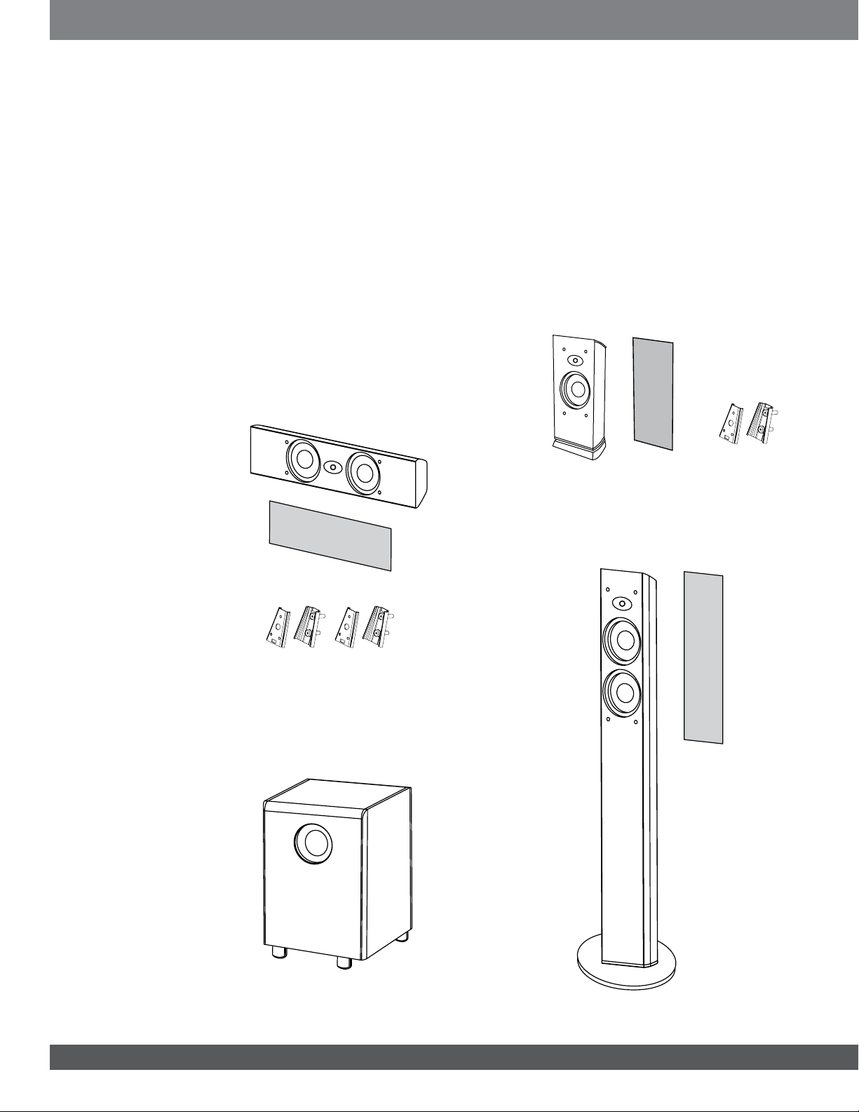
INCLUDED ItEMS
EACH MODEL SOLD SEPARATELY
CSB6
CSC56
Grille
Two wall brackets
CSS11
CST56
Grille
One wall bracket
Grille
4
Page 5

SpEAkER pLACEMENt
0 – 2 ft
0 – 0.6m
FRONT SPEAKERS CENTER-CHANNEL SPEAKER SUBWOOFER
Listening
position
SURROUND SPEAKERS
Alternate placement for surround speakers
when only 5.1 channels are used; required
placement for surround back speakers in
7.1-channel systems.
† Single surround back speaker may
be used with 6.1-channel receivers and
processors.
English
The front speakers should be placed the same distance from each other as they are from the listening position. The
CSB6 speakers should be placed at about the same height from the floor as the listeners’ ears will be, or they may be
angled toward the listeners.
The center channel speaker should be placed slightly behind the front left and right speakers, and no more than 2 feet
(0.6m) above or below the tweeters of the left and right speakers. It is often convenient to set the center speaker on
top of the television set, as shown in the drawing.
The JBL Cinema Sound speaker system may be used in 5.1-, 6.1- or 7.1-channel applications. In 5.1-channel
applications, two of the surround speakers should be placed slightly behind the listening position and, ideally, should
face each other and be at a level higher than the listeners’ ears. If that is not possible, they may be placed against a
wall behind the listening position, facing forward. In 6.1-channel applications, two of the surround speakers should be
placed in the side positions, and a single surround back speaker should be placed against the wall behind the listening
position. In 7.1-channel applications, place two of the surround speakers in the side positions, and place the two
surround back speakers against the back wall.
In Dolby® Digital and DTS® systems, it is best to aim all of the speakers (except the subwoofer) toward the listening
position at or slightly above ear-level height. In systems where only analog surround processing (such as Dolby Pro
Logic® II) is available, it may be preferable to aim the speakers straight out from the wall to obtain a more diffuse
sound.
The low-frequency sound from the subwoofer radiates in all directions, and this speaker may be placed in a convenient
location in the room. However, bass reproduction will be maximized when the subwoofer is placed in a corner along
the same wall as the front speakers. Experiment with subwoofer placement by temporarily placing the subwoofer in the
listening position and moving around the room until the bass reproduction sounds best. Place the subwoofer in that
location.
www.jbl.com
5
Page 6

WALL-MOUNtINg thE CSC56 AND CSB6
The CSC56 center channel and the CSB6 are designed to be mounted on the wall. There are two (2) fixed-mount wall
brackets provided for the CSC56, and one for the CSB6. Each speaker bracket will require up to three 1-1/2" #10
wood screws; each screw should be fastened to a wall stud. If a wall stud is unavailable, install an anchor appropriate
for a 1-1/2" #10 screw.
NOTE: The customer is responsible for the correct selection and use of mounting hardware (available through hardware
stores) to ensure the proper and safe wall-mounting of the speakers.
Step 1: Using the included mounting template (CSC56 only) or the bracket back plate (CSB6 only), mark the positions
on the wall where you would like to place the mounting screws.
Step 2: Attach the back plate(s) of the brackets to the wall using three screws (not included).
Step 3: Attach the front plate(s) (with the two holes) of the bracket(s) to the CSC56 or CSB6, using the provided
screws.
Step 4: Slide the CSC56 or CSB6 speaker with the attached bracket front plate(s) onto the back plate(s) of the
bracket(s). Once positioned properly, the speaker should slide down slightly and become secure.
To remove the speaker from the wall, simply slide the speaker up.
CSC56
CSB6
NOTE: Remove the base
of the CSB6 by removing
the two screws on the
bottom of the speaker.
6
Page 7

SpEAkER CONNECtIONS
CONNECTION TIPS
Separate and strip the ends of the speaker wire as shown. Speakers and other electronic components have
corresponding (+) and (–) terminals. Most manufacturers of speakers and electronics, including JBL electronics, use
red to denote the (+) terminal and black to denote the (–) terminal.
The (+) lead of the speaker wire is noted with a stripe. It is important to connect both speakers identically: (+) on the
speaker to (+) on the amplifier and (–) on the speaker to (–) on the amplifier. Wiring “out of phase” results in thin sound,
weak bass and a poor stereo image.
With the advent of multichannel surround sound systems, it is equally important to connect all of the speakers in your
system with the correct polarity in order to preserve the proper ambience and directionality of the sound.
English
CST56
To provide a neater installation, the CST56 allows you to insert the speaker wires through holes in the base. Simply
separate and strip the wires as described above, loosen the terminals and insert each wire into its corresponding hole
in the base. Then tighten down the terminals.
The hole in the center of each collar is intended for use with banana-type connectors. To comply with European CE
certification, these holes are blocked with plastic inserts at the point of manufacture. To use banana-type connectors
requires the removal of the inserts.
CSB6, CSC56
To use the binding-post speaker terminals, unscrew the colored collar until the pass-through hole in the center
post is visible under the collar. Insert the bare end of the wire through this hole; then screw the collar down until the
connection is tight. The hole in the center of each collar is intended for use with banana-type connectors. To comply
with European CE certification, these holes are blocked with plastic inserts at the point of manufacture. To use bananatype connectors requires the removal of the inserts.
www.jbl.com
7
Page 8

SpEAkER CONNECtIONS
LINE
LEVEL
IN
LFE
L
R
LFE OUT
RECEIVER SUBWOOFER
– +
– +– +
– +
– +
– +
– +
– +– +
Left
Surround
Left
Front
Right
Front
Center
Front Right
Surround Right
Subwoofer
Receiver
Subwoofer
Out
Line
Level In
L
Front Left
Surround Back
Left
Surround Back
Right
Surround Back
Left Right
Surround
Center
Surround Back
Right
– +
Surround Left
– +
– +
– +
– +
R
RL
DOLBy® DIgItAL OR DtS® (OR OthER DIgItAL SURROUND MODE) CONNECtION
Use this installation method for Dolby Digital, DTS or other digital surround processors:
Use the line-level input jack marked “LFE” for the Low-Frequency Effects channel. Connect this jack to the LFE output
or subwoofer output on your receiver or amplifier. Connect each speaker to the corresponding speaker terminals on
your receiver or amplifier.
Make sure that you have configured your surround-sound processor for “Subwoofer On.” Also, configure your receiver
for 5.1-, 6.1- or 7.1-channel operation as appropriate. The front left, front right, center and back speakers should
all be set to “Small.” If your receiver allows you to set the crossover frequency between the subwoofer and the main
speakers, select 100Hz or the setting that is the closest frequency below it.
DOLBY PRO LOGIC
®
(NON-DIGITAL) – LINE LEVEL
Use this installation method for Dolby Pro Logic® applications (not Dolby Digital, DTS or other digital processing),
where the receiver/processor is equipped with a subwoofer output or a volume-controlled preamp (line-) level output:
Use RCA-type cables to connect the line-level subwoofer outputs on your receiver or amplifier to the line-level inputs
on the subwoofer. IMPORTANT: Do not use the LFE input on the subwoofer with Dolby Pro Logic processors.
8
NOTE: If your receiver or amplifier has only one subwoofer output jack, then you will need to use a Y-connector (not
included). Plug the male end of the Y-connector into your receiver or amplifier’s subwoofer output jack, and connect
each of the two female ends to separate RCA-type interconnects. Finally, plug the RCA-type interconnects into the
line-level inputs on the subwoofer.
Connect each speaker to the corresponding speaker terminals on your receiver or amplifier. Make sure your receiver or
processor is correctly configured to indicate that the subwoofer is “On.”
Page 9

SUBWOOfER OpERAtION
MIN MAX
MIN MAX
English
Press the Master Power switch (marked “Power” å) to the On position to use the subwoofer. The CSS11 subwoofer
will automatically turn on or go into Standby (sleep) mode as described below. When your receiver or amplifier is off, or
is not sending program material to the subwoofer, the subwoofer will be in standby mode (the LED on the front of the
CSS11 will be red). When the subwoofer senses an audio signal, it will automatically turn on (the LED will be green). If
the subwoofer does not sense a signal after approximately 20 minutes, it will automatically go into Standby mode.
If you will be away from home for an extended period of time, or if the subwoofer will not be used, switch the Master
Power switch å to the Off position by pressing it until it pops out.
VOLUME
Volume may be adjusted using the Subwoofer Level control ∫, as shown.
PHASE
The Phase control determines whether the subwoofer’s pistonlike action moves in and out in phase with the main
speakers or opposite the main speakers. There is no correct or incorrect setting. Proper phase adjustment depends
on several variables, such as subwoofer placement and listener position. Adjust the Phase switch ç to maximize bass
output at the listening position.
Remember, every system, room and listener is different. There are no right or wrong settings; this switch offers the
flexibility to adjust your subwoofer to optimum performance for your specific listening conditions without moving
your speakers. If at some time in the future you happen to rearrange your listening room and move your speakers,
you should experiment with the phase switch in both positions and leave it in the position that maximizes bass
performance.
www.jbl.com
9
Page 10

tROUBLEShOOtINg
pROBLEM SOLUtION
If there is no sound fro m any of the
speakers:
If there is no sound coming from one
speaker:
If there is no sound fro m the center
speaker:
If the system plays at low volumes but
shuts off as volume is increased:
If there is low (or no) bass output:
If there is no sound from the surround
speakers:
Check that receiver/amplifier is on and a source is playing.•
Check that the powered subwoofer is plugg ed in and is turn ed on (Power •
switch å pushed in).
Check all wires and connections bet ween receiver/amplifier and speakers. •
Make sure all wire s are connected. Make sure none of th e speaker wires are
frayed, cut, punctured or touching each other.
Review proper operation of your receiver/amplifier.•
Check the Balance control on your receiver/amplifier.•
Check all wires and connections bet ween receiver/amplifier and speaker. •
Make sure all wire s are connected. Make sure none of th e speaker wires are
frayed, cut, punctured or touching each other.
In Dolby Digital or DTS modes, make sure that the receiver/amplifier is •
configured so that the speaker in question is enabled.
Turn off all electron ics, and switch the speaker in question with one of •
the other speakers that is working correc tly. Turn everything back on, and
determine whether the problem has followed the speaker or has remained in
the same channel. If the problem is in th e same channel, the source of the
problem is most likely with your receiver or amplifier, and you should consult
the owner’s manual fo r that product for further information. If the problem has
followed the speaker, consult your dea ler fo r further assistance or, if that is
not possible, visit www.jbl.com.
Check all wires and connections bet ween receiver/amplifier and speaker. •
Make sure all wire s are connected. Make sure none of th e speaker wires are
frayed, cut, punctured or touching each other.
If your receiver/process or is set in Dolby Pro Logic mode, make sure the •
center speaker is not in phantom mode.
If your receiver/process or is set in one of the Dolby Digital or DTS modes, •
make sure the rece iver/p rocessor is configured so that the center speaker is
enabled.
Check all wires and connections bet ween receiver/processor and speakers. •
Make sure all wire s are connected. Make sure none of th e speaker wires are
frayed, cut, punctured or touching each other.
If more than one pair of main speak ers is being used, check the minimum •
impedance requirements of your receiver/amplifier.
Make sure the connections to the le ft and right speaker inputs have the •
correct polarity (+ and –).
Make sure the subwoofer is plugged into a n active electrical outlet and is •
turned on (Power switch å pushed in).
In Dolby Digital or DTS modes, make sure your receiver/processor is •
configured so that the subwoofer and LFE output are enabled.
Switch the Phase switch • ç to the opposite position, and select the position
that results in the most pleasing bass response.
Check all wires and connections bet ween receiver/processor and speakers. •
Make sure all wire s are connected. Make sure none of th e speaker wires are
frayed, cut, punctured or touching each other.
Review the proper operation of your receiver/amplifier and its surround- sound •
features.
Make sure the movie or TV show you are watching is recorded in a surround •
sound mode. If it is not, check to see whether your receiver/processor has
other surround modes you may use.
In Dolby Digital or DTS modes, make sure your receiver/processor is •
configured so that the surround speakers are enabled. When five satellit es
are in use, rememb er to configure your receiver or processor for 6.1-channel
operation, and when six satellites are in use, configure your receiver or
processor for 7.1 channels.
Review the operation of your DVD player and the jacket of your D VD to make •
sure that the DVD features the desired Dolby Digital or DTS mode, and th at
you have properly selected that mode using both the DVD player’s menu and
the DVD disc’s menu.
10
Page 11

SpECIfICAtIONS
SYSTEM
Frequency response: 27Hz – 30kHz (–6dB)
CST56 CSB6 CSC56
English
Maximum recommended
amplifier power:
Power handling: 50W continuous/300W peak 40W continuous/300W peak 50W continuous/300W peak
Frequency response: 55Hz – 30kHz (–6dB) 60Hz – 30kHz (–6dB) 55Hz – 30kHz (–6dB)
Nominal impedance: 8 ohms 8 ohms 8 ohms
Sensitivity: 90dB @ 1 watt/1 meter 88dB @ 1 watt/1 meter 90dB @ 1 watt/1 meter
Tweeter: 3/4" (19mm) titanium-laminate
Woofers: Dual 5" (130mm) transducers
Dimensions (H x W x D): 46" x 11-1/4" x 11-1/4"
Weight: 17 lb (7.7kg) Including base and grille:
150W* 125W* 150W*
dome, video-shielded
with PolyPlas
neodymium magnets and
HeatScape™ motor structure,
video-shielded
(1168mm x 286mm x 286mm)
(including base and grille)
™
cones,
3/4" (19mm) titanium-laminate
dome, video-shielded
5" (130mm) transducer with
PolyPlas cone, neodymium
magnet and HeatScape motor
structure, video-shielded
Including base and grille:
14-5/16" x 6-1/8" x 4-9/16"
(363mm x 155mm x 116mm)
Without base but with wallmount bracket and grille:
13-5/16" x 6-1/8" x 5-1/8"
(338mm x 155mm x 130mm)
5 lb (2.3kg)
Without base and with wallmount bracket and grille:
4.5 lb (2kg)
3/4" (19mm) titanium-laminate
dome, video-shielded
Dual 5" (130mm) transducers
with PolyPlas cones, neodymium
magnets and HeatScape motor
structure, video-shielded
6-1/4" x 26-1/4" x 4-1/4"
(159mm x 667mm x 108mm)
(including wall-mount bracket
and grille)
10 lb (4.5kg)
CSS11
Amplifier power: 150W RMS
Frequency response: 27Hz – low-pass crossover setting at signal source
Low-frequency driver: 10" (250mm) cone and HeatScape motor structure, video-shielded
Input: LFE preamp level
Dimensions (H x W x D) (including feet): 18-1/4" x 13-1/4" x 16" (464mm x 337mm x 406mm)
Weight: 43 lb (19.5kg)
*The maximum recommended amplifier power rating will ensure proper system headroom to allow for occasional peaks.
We do not recommend sustained operation at these maximum power levels.
Features, specifications and appearance are subject to change without notice.
www.jbl.com
11
Page 12

Harman Consumer, Inc.
8500 Balboa Blvd., Nor thridge, CA 91329 USA
© 2010 Harman International Industries, Incorporated. All rights reserved.
JBL is a trademark of Harman International Industries, Incorporated,
registered in the United States and/or other countries. PolyPlas and
HeatScape are trademarks of Harman International Industries, Incorporated.
Dolby and Pro Logic are registered trademarks of Dolby Laboratories. DTS
is a registered trademark of Digital Theater Systems, Inc.
Part No. 950-0317- 001 Rev. B
www.jbl.com
 Loading...