

Page 1
CS Series
CS60.4
4 CHANNEL POWER AMPLIFIER
SERVICE MANUAL
JBL Consumer Products
250 Crossways Park Dr.
Woodbury, New York 11797 Rev0 11/2005
Page 2

CS Series 60.4
1
- CONTENTS -
SPECIFICATIONS ………………………………………..1
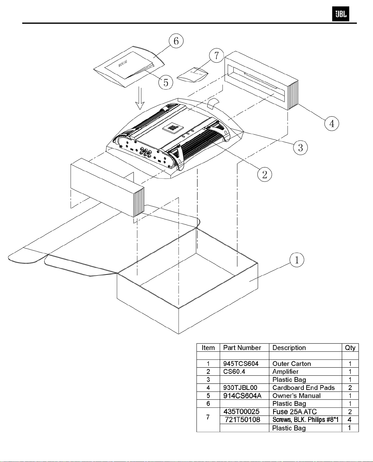
PACKAGING……………………………………………….2
CONNECTIONS..…….…….….……………………..……3
SET-UP/CONTROLS..………………………………....…4
BASIC TROUBLESHOOTING..…….…….………………4
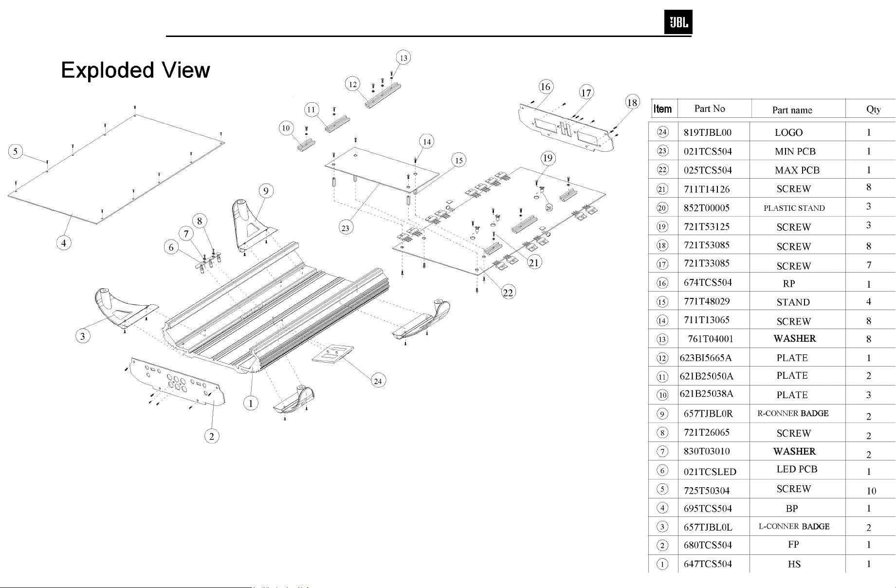
EXPLODED VIEW/PART S LIST…….….….…………....5
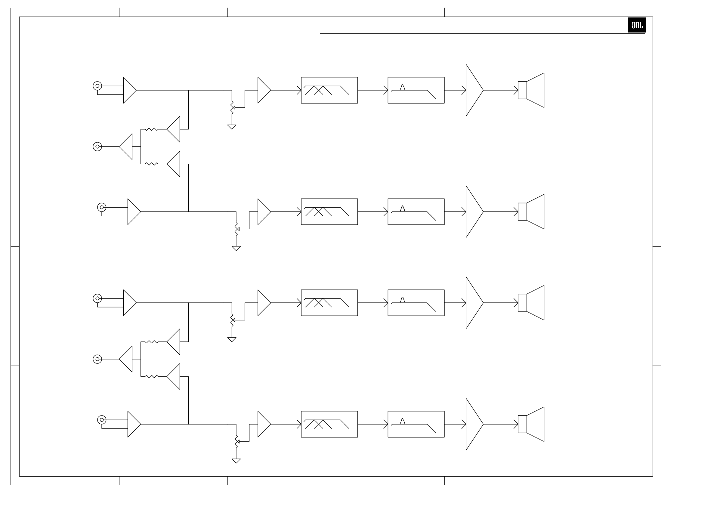
AMPLIFIER BLOCK DIAGRAM…………………….……6
P.C . B. DRAWINGS….……………………………….…….7
ELECTRICAL PARTS LIST ..……….……….…….….…11
IC/TRANSISTOR PINOUTS..……..….…….….….….…..15
SCHEMATICS………..…………………………….……...16
CS60.4 Specifications
Output Power: 60W RMS x 4 channels @ 4 ohms; ≤1% THD + N
(14.4V supply) 80W RMS x 4 channels @ 2 ohms; ≤1% THD + N
160W RMS x 2 channels @ 4 ohms; ≤1% THD + N
Signal-to-noise ratio: 86dBA (reference 1W into 4 ohms)
Dynamic power: 145W @ 2 ohms
Effective damping factor: 6.395 @ 4 ohm s
Frequency response: 10Hz – 27kHz (–3dB)
Maximum input signal: 6V
Maximum sensitivity: 100mV
Bass boost (45Hz) Variable 0 – 6dB
DC Offset <30mV
Output regulation: .03dB @ 4 ohms
Idle Current 0.65A
Input Impedance 20kΩ
Max Current Draw 26A @ 4 ohms
49A @ 2 ohms
Dimensions: 13 1/4 x 10 1/4 x 2 3/16” (L x W x H)
(336mm x 260mm x 55mm)
Fuses: 25A x 2
JBL continually strives to update and improve existing product s, as wel l as create new ones. The specifications and
details in this and related JBL publications are therefore subject to change without notice.
Page 3
CS Series 60.4
2
Page 4
CS Series 60.4
3
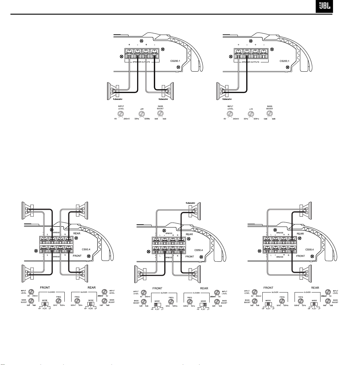
APPLICATIONS – CS200.1
The CS subwoofer amplifier is a
single-channel amplifier. There are
two sets of terminals to make it easy
to connect multiple woofers. Either
set of (+/–) terminals may be used
when connecting woofers.
To the right are two application
diagrams to help plan your subwoofer
system installation.
show how to configure the CS200.1
subwoofer amplifier.
NOTE: For simplicity, Figures 2 and 3
do not show power, remote and input
connections.
Figures 2 and 3
NOTE: Minimum speaker load is
2 ohms total.
Figure 2. CS subwoofer amplifier with two woofers
connected.
APPLICATIONS – CS60.4
The CS60.4 can be set up for stereo
4-channel, 3-channel or bridged
2-channel operation, as shown in
Figures 4 through 6.
NOTE: For simplicity, Figures 4 through
6 do not show power, remote and input
connections.
Figure 3. CS subwoofer amplifier with one woofer
connected.
NOTE: Minimum speaker impedance
for stereo operation is 2 ohms.
Minimum speaker impedance for
bridged operation is 4 ohms.
Figure 4. CS60.4 amplifier in 4-channel (stereo)
operation to drive front and rear full-range speakers.
Figure 5. CS60.4 is set up for 3-channel operation to
drive a set of full-range speakers and a subwoofer.
Figure 6. CS60.4 used in bridged 2-channel mode
to drive a set of components or subwoofers. Set
crossovers according to application.
Page 5
Features, specifications and appearance are subject to change without notice.
CONTROLS AND SETUP
SYMPTOM LIKELY CAUSE SOLUTION
No audio No voltage at BATT+ Check voltages at
(POWER LEDs or REM terminals, amplifier terminals
are off) or bad or no ground with VOM
connection
No audio Amplifier is Make sure amplifier
(POWER overheated cooling is not blocked
LEDs are on) at mounting location;
verify speaker-system
impedance is within
specified limits
Voltage more than 16V Check vehicle
or less than 8.5V on charging system
BATT+ connection
SYMPTOM LIKELY CAUSE SOLUTION
No audio Voltage less than 9V on Check vehicle
(POWER BATT+ connection charging system
LEDs flash)
DC voltage on Amplifier may need
amplifier output service; see enclosed
warranty card for
service information
Distorted audio Input sensitivity is Check INPUT
not set properly, or LEVEL setting; or
amplifier or source check speaker wires
unit is defective for shorts or grounds
Distorted audio Short circuit in Remove speaker leads
and POWER speaker or wire one at a time to locate
LEDs flash shorted speaker or
wire, then repair
Music lacks Speakers are not Check speaker
“punch” connected properly connections for
proper polarity
SETTING THE
CROSSOVER(S)
SETTING INPUT
SENSITIVITY
1. Initially turn the INPUT LEVEL control(s)
to minimum (counter clockwise).
2. Reconnect the (–) negative lead to the
vehicle’s battery. Apply power to the
audio system and play a dynamic music
track.
3. On the source unit, increase the volume
control to 3/4 volume. Slowly increase
the INPUT LEVEL control(s) toward three
o’clock until you hear slight distortion
in the music. Then reduce the INPUT
LEVEL slightly until distortion is no
longer heard.
NOTE: After the source unit is on, blue
LEDs (on the top panel) will light, indicating
the amplifier is on. If not, check the wiring,
especially the remote connection from the
source unit. Also refer to “Troubleshooting”
guide below.
TROUBLESHOOTING
CS Series 60.4
4
Determine your system plans and set
the crossover mode switch accordingly.
If your system design does not include
a subwoofer with the CS60.4, set the
crossover mode to FLAT and skip to
“Setting Input Sensitivity.”
Initially set the crossover frequency
control midway. While listening to music,
adjust the crossover for the least
perceived distortion from the speakers,
allowing them to reproduce as much
bass as possible.
Systems using a separate subwoofer set
the crossover mode to HP (high pass) for
your full-range speakers. Adjust the
crossover frequency to limit bass and
provide increased system volume with
less distortion.
For subwoofers, choose the highest
frequency that removes vocal information
from the sound of the subwoofer.
If using the CS60.4 to drive a subwoofer(s),
set the crossover mode to LP (low pass).
Page 6
CS Series 60.4
5
Page 7
54321
6
6
CS Series 60.4
MODE HP/FLAT/LP
BALANCED
D
INPUT
INPUT
(UNIT GAIN)
VARIABLE LPF/HPF
32Hz--320Hz/12dB
BOOST
VARIABLE
0dB--6dB/45Hz
MAIN AMP
FRONT L
2 ohm/4 ohm
D
FRONT L
AUX OUT
Ap
10 320 20K
Ap
Ap
10 50 20K
Ao
SPEAKER
FRONT L+ REAR L
Ap
Ap
MODE HP/FLAT/LP
BALANCED
C
INPUT
INPUT
(UNIT GAIN)
VARIABLE LPF/HPF
32Hz--320Hz/12dB
BOOST
VARIABLE
0dB--6dB/45Hz
MAIN AMP
REAR L
2 ohm/4 ohm
C
REAR L
Ap
10 320 20K
Ap
10 50 20K
Ao
SPEAKER
MAIN AMP
FRONT R
2 ohm/4 ohm
INPUT
BALANCED
INPUT
(UNIT GAIN)
MODE HP/FLAT/LP
VARIABLE LPF/HPF
32Hz--320Hz/12dB
VARIABLE
0dB--6dB/45Hz
FRONT R
10 320 20K
B
Ap
AUX OUT
Ap
Ap
10 50 20K
Ao
SPEAKER
B
FRONT R+ REAR R
Ap
Ap
MAIN AMP
REAR R
2 ohm/4 ohm
INPUT
BALANCED
INPUT
(UNIT GAIN)
MODE HP/FLAT/LP
VARIABLE LPF/HPF
32Hz--320Hz/12dB
BOOST
VARIABLE
0dB--6dB/45Hz
REAR R
10 320 20K
A
Ap
Ap
10 50 20K
Ao
SPEAKER
A
1 2 3 4 56
Page 8

CS Series 60.4
7
Page 9

CS Series 60.4
8
Page 10

CS Series 60.4
9
Page 11

CS Series 60.4
10
Page 12

p
p
-
CS Series 60.4
11
CS 60.4 Electrical Parts List
Part Number Description Qty Reference Designator
Note on Numbering Sequence, all components: "D1~7" (tilde mark) means D1,2,3,4,5,6,7.
but "D136-D436" (hyphen) means D136,236,336,436"
Main PCB
Semiconductors
124TN4401 Transistor TR MOTOROLA 2N4401 NPN 18
124TN4403 Transistor TR MOTOROLA 2N4403 PNP 11 Q6 Q9 Q10 Q136-Q436 Q137-Q437
124T0SA06 Transistor
125T0C945 Transistor TR NEC 2SC945P 0.1A60V NPN 4 Q144-Q444
126TSB647 Transistor 2SB647A PNP 6 Q7 Q8 Q146-Q446
126TSD667 Transistor 2SD667A NPN 5 Q14 Q141-Q441
129T0J109 Transistor J109 1 Q1
131TN4148 DIODE DIODE NS1N4148HSS150MA 13 D1~7 D11~16
133T0J5B6 ZINER DIODE DIODE NECRD5.6JSB ZNR5.6V 1 ZD1
133T0011B ZINER DIODE DIODE NEC RD11EB3 11V 1 ZD2
133T0015B ZINER DIODE DIODE NEC RD15EB3 15V 2 ZD3 ZD4
155TTL431 IC DIP3 TL431 adjustable shunt regulator 1 Q3
124T0SA56 Transistor
124TN4401 Transistor TR MOTOROLA 2N4401 NPN 3 Q243 Q343 Q443
134TN4002 RECTIFIER DIODE DIODE 1N4002 RET1.0A100V 8 D135-D435 D136-D436
134TN5402 RECTIFIER DIODE DIODE 1N5402 ET3.0A100V 1 D9
151T04558 IC SIP8 JRC MC4558 Dual Op-Amp 1 IC202
154T04558 IC DIP8
154LM358N IC DIP8 DIP8 LM358N Dual Op-Amp 1 IC2
158TTL494 IC DIP16 NEC UPC494 or TI TL494 PWM 1 IC1
123TRFZ48 Transistor IR IRFZ48V MOSFET 4 Q1~13,Q15
128TKD718 Transistor KD718 NPN 4 Q142-Q442
128TKB688 Transistor KB688 PNP 4 Q147-Q447
135T1620C DIODE DIODE MOTOROLA 1620CT 1 D8
135T1620R DIODE DIODE MOTOROLA 1620CTR 1 D10
TR MOTOROLA MPSA06 80V NPN
TR MOTOROLA MPSA56 80V PNP
JRC or ROHM BA4558 Dual O
-Am
Q2 Q4 Q5 Q16 Q17,Q138-Q438,Q140-Q440
Q135-Q435 Q143
4 Q145-Q445
4 Q139-Q439
6 IC101-IC401 102-402, 203, 403
Resistors
22022047A RESISTOR RD 1/2W 4.7Ω 4 R152-R452
220440101 RESISTOR RD 1/4W 100Ω 4 R25 R26 R28 R29
220440103 RESISTOR RD 1/4W 10K 4 R154-R454
220440272 RESISTOR RD 1/4W 2.7K 4 R151-R451
220880000 RESISTOR RD 1/8W 0Ω 29
220880101 RESISTOR RD 1/8W 100Ω 18
220880102 RESISTOR RD 1/8W 1K 19
220880103 RESISTOR RD 1/8W 10K 11 R135-R435 R10 R19 R20 R108-R408
220880104 RESISTOR RD 1/8W 100K 8 R2~6 R12 R124 R224
220880123 RESISTOR RD 1/8W 12K 1 R17
220880153 RESISTOR RD 1/8W 15K 2 R49 R50
220880154 RESISTOR RD 1/8W 150K 2 R43 R42
220880183 RESISTOR RD 1/8W 18K 9 R35 R140-R440 R141-R441
220880202 RESISTOR RD 1/8W 2K 2 R40 R41
230884421 RESISTOR MF1/8W 4.42K 1% 4 R144-R444
220880204 RESISTOR RD 1/8W 200K 1 R23
220880205 RESISTOR RD 1/8W 2M 1 R22
220880221 RESISTOR RD 1/8W 220Ω 4 R148-R448
220880222 RESISTOR RD 1/8W 2.2K 1 R36
220880223 RESISTOR RD 1/8W 22K 6 R45 R30 R100-R400
220880242 RESISTOR RD 1/8W 2.4K 4 R147-R447
JP1 JP18 JP24 JP30 JP35~39 JP41~51 JP53
JP86 JP101~103 R103-R403
R11R27.R138-R438 R139-R439 R142-R442 R143
R443
R7 R14 R15 R137-R437 R156-R456 R157-R457
R136-R436
Page 13

CS Series 60.4
12
Part Number Description Qty Reference Designator
Note on Numbering Sequence, all components: "D1~7" (tilde mark) means D1,2,3,4,5,6,7.
but "D136-D436" (hyphen) means D136,236,336,436"
Main PCB
220880243 RESISTOR RD 1/8W 24K 2 R123 R223
220880272 RESISTOR RD 1/8W 2.7K 1 R24
220880302 RESISTOR RD 1/8W 3K 4 R9 R18 R39 R38
220880363 RESISTOR RD 1/8W 36K 1 R51
220880391 RESISTOR RD 1/8W 390Ω 4 R111-R411
220880392 RESISTOR RD 1/8W 3.9K 1 R13
220880470 RESISTOR RD 1/8W 47Ω 8 R145-R445 R158-R458
220880472 RESISTOR RD 1/8W 4.7K 4 R146-R446
220880473 RESISTOR RD 1/8W 47K 10 R1 R34 R101-R401 R102-R402
220880474 RESISTOR RD 1/8W 470K 1 R44
220880562 RESISTOR RD 1/8W 5.6K 4 R155-R455
220880563 RESISTOR RD 1/8W 56K 9 R52 R109-R409 R110-R410
220880682 RESISTOR RD 1/8W 6.8K 2 R46 R16
220880821 RESISTOR RD 1/8W 820Ω 4 R153-R453
230881002 RESISTOR MF 1/8W 10K 1% 1 R48
230881003 RESISTOR MF 1/8W 100K 1% 4 R105-R405
230881052 RESISTOR MF 1/8W 10.5K 1% 1 R47
230882202 RESISTOR MF 1/8W 22K 1% 1 R8
230884751 RESISTOR MF 1/8W 4.75K 1% 6 R213 R413 R112-R412
230884991 RESISTOR MF 1/8W 4.99K 1% 2 R113 R313
220220220 RESISTOR RD 1/2W 22Ω 1 R37
220220470 RESISTOR RD 1/2W 47Ω 2 R33 R32
220880472 RESISTOR RD 1/8W 4.7K 4 C103~403
231100101 RESISTOR 1Ws 100Ω 1 R31
232XL502J CEMENT RESISTOR SQM 5Ws 0.2Ω 8 R149-R449 R150-R450
202G09B23 Variable Resistor B20K 20% H=15L=9 Input Lev. 2 VR101 VR201
Capacitors
31K510010 CERAMIC CAPACITOR C/C NPO 10pF 100V K 4 C101-C401
31Z510305 CERAMIC CAPACITOR C/C Y5V 10000pF 50V Z 1 C35
31Z510410 CERAMIC CAPACITOR C/C Y5V 0.1uF 100V Z 8 C6~9 C10 C11 C31 C32
31J547010 CERAMIC CAPACITOR C/C NPO 47pF 100V J 18
31J568125 CERAMIC CAPACITOR C/C Y5E 680pF 250V K 1 C22
32J510410 M/C M/C 0.1uF 100V J 8 C143-C443 C138-C438
32J568210 M/C M/C 0.0068uF 100V J 1 C20
340Z10625 Electrolytic Cap 10uF 25V 5*11 6 C112 C212 C129-C429
340Z10716 Electrolytic Cap 100uF 16V 5*11 10 C4 C19 C27~30 C141-C441
340Z22550 Electrolytic Cap 2.2uF 50V 5*11 3 C3 C34 C33
340Z22616 Electrolytic Cap 22uF 16V 1 C21
340Z22625 Electrolytic Cap 22uF 25V 5*11 9 C2 C100-C300 C402 C104-C404
340Z47625 Electrolytic Cap 47uF 25V 5*11 3 C5 C36 C14
370Z10550 Electrolytic Cap 1uF 50V 5*11 3 C239 C339 C439
370Z10716 Electrolytic Cap 100uF 16V 8*12 1 C18
370Z22616 Electrolytic Cap 22uF 16V NP 1 C1
390Z22625 Electrolytic Cap 22uF 25V 4*7 4 C102 C202 C302 C400
340T10750 Electrolytic Cap 100uF 50V 8*13 8 C135-C435 C140-C440
341T22835 Electrolytic Cap 2200uF 35V 16*26 105C 4 C23~26
341T10835 Electrolytic Cap 1000uF 35V 13*26 105C 3 C15~17
370Z10550 Electrolytic Cap 1uF 50V 5*11 1 C139
370Z10625 Electrolytic Cap 10UF/25V 5*11 4 C103-C403
Miscellaneous
C12 C13 C136-C436 C142-C442 C137-C437
C105-C405
261T05103 THERMISTOR NTC THERMISTORD103J 10K 2 RTH1 RTH2
173T00102 INDUCTOR 102UH 1 JP89
401T25040 COPPER BAR φ2.5*40m/m H=20 1
Page 14

CS Series 60.4
13
Part Number Description Qty Reference Designator
Note on Numbering Sequence, all components: "D1~7" (tilde mark) means D1,2,3,4,5,6,7.
but "D136-D436" (hyphen) means D136,236,336,436"
Main PCB
401T25815 COPPER BAR φ2.5*81.5m/m H=20 1
410T21004 BUSS BAR 4P2.1*55.5m/m 1 JP134
571T20070 CONNECTOR W/WIRE 1015# 20AWG 70m/m 1 GND
572TB6012 CONNECTOR W/WIRE 12P 60m/m(CN*2) 1 J4
862T00010 FIBER SLEEVE 10m/m φ1.0 4 RTH1 RTH2
862T00020 FIBER SLEEVE 20m/m φ1.0 1 JP91
172T41050 INDUCTOR T23*90-26 1.0*4*71/2TS5. 1 L1
181T37612 TRANSFORMER ψ37 6:12 L=ψ1.2*3*6Ts 1 T1
435T00025 FUSE 25A ATC 2 F1
447T00001 FUSE HOLDER 1 for F1
526URDW14 RCA JACK 6 HOLE 14P 1 RCA1
535T25002 CONNECTOR 2P P=2.5m/m 1 J3
544T300003 TERMINAL GA30-03-3P 1 J1
544T34324 TERMINAL EM-2304 4P*2+C150 1 J2
Pre-Amp PCB, LED board
Semiconductors
154T04558 IC DIP8 ROHM BA4558 10 IC104-IC404 IC103 IC303 IC105-IC405
P137T05B02 LED 5ψLED BLUE LIGHT 3 BLED1 BLED2 BLED3
Resistors
220880000 RESISTOR RD 1/8W 0Ω 13
220880102 RESISTOR RD 1/8W 1K 4 R119-R419
220880103 RESISTOR RD 1/8W 10K 16 R104-R404 R106-R406 R107-R407 R114-R414
220880223 RESISTOR RD 1/8W 22K 4 R115-R415
220880362 RESISTOR RD 1/8W 3.6K 4 R120-R420
220880392 RESISTOR RD 1/8W 3.9K 4 R122-R422
220880474 RESISTOR RD 1/8W 470K 4 R125-R425
220880562 RESISTOR RD 1/8W 5.6K 11 R116-R416 R117-R417 R121 R221 R421
220880682 RESISTOR RD 1/8W 6.8K 4 R118-R418
220880562 RESISTOR RD 1/8W 5.6K 1 R321
202G13B23 Variable Resistor B20K 20% H=15 L=13 2 VR103 VR303
202G15C53 Variable Resistor C50K 20% H=15 L=22 2 VR102 VR302
Capacitors
31J510110 CERAMIC CAPACITOR C/C NPO 100pF 100V J 4 C106-C406
31K547110 CERAMIC CAPACITOR C/C Y5E470pF 100V K 4 C11 C211 C311 C411
32J539310 M/C M/C 0.039uF 100V J 4 C110-C410
32J582310 M/C M/C 0.082 uF 100V J 8 C107-C407 C108-C408
340Z10716 Electrolytic Cap 100uF 16V 5*11 2 CN1 CN2
31Z510410 CERAMIC CAPACITOR C/C Y5V 0.1uF 100V Z 2 CN3 CN4
32J518410 Electrolytic Cap M/C 0.18uF 100V J 4 C109-C409
NP1~NP4 NP10 NP22 NP25 NP30 NP33 NP34
NP36 NP37 NP39
Miscellaneous
192R23D05 SWITCH SK-23D05 G=7 2 SW100 SW300
531T25012 CONNECTOR 12P P=2.5m/m 1 J5
MISC./MECHANICAL
571W15002 CONNECTOR W/WIRE 2P 150 T=5m/m 1
621B25038A TRANSISTOR BAR 1 HOLE 2.5*15*38m/m 3
621B25050A TRANSISTOR BAR 1HOLE 2.5*15*50m/m 2
Page 15

CS Series 60.4
14
Part Number Description Qty Reference Designator
Note on Numbering Sequence, all components: "D1~7" (tilde mark) means D1,2,3,4,5,6,7.
but "D136-D436" (hyphen) means D136,236,336,436"
MISC./MECHANICAL
623BI2565A TRANSISTOR BAR 3HLE 2.5*12*65m/m 1
647TCS604-A
674TCS604-A
680TCS604 RCA PANEL CS60.4 1
711T13065 SCREW PMS 3*6m/m 8
711T14145 SCREW M4*14m/m 8
721T33085 SCREW PTS-1)3*8 7
721T53125 SCREW PTS-4 3*12 3
721T53085 SCREW PTS-2 3*8 8
721T26065 SCREW PT 2.6*6m/m 2
761T04001 SPRING WASHER 4φ 8
771T48029 COPPER STANDOFF 29.0*4.75m/m 4
820TJBL00 NAME BADGE CS60.2&CS300.1&CS60.4共用 1
830T03010 INSULATOR 3*10*1m/m 2
830T30010 WASHER 300*10*0.5m/m 1
831T25046A INSULATOR 1孔 25*46m/m 5
833T23065A INSULATOR 3孔 23*65m/m 1
843101025 RUBBER WASHER 10*10m/m T=2.5 2
843389535 RUBBER WASHER 38*9.5*3.5m/m 1
852T00005 STANDOFF H=5m/m PCB 3
657TJBL0L-A LEFT MOUNTING BRKT CS60.4&CS300.1&CS60.2 2
657TJBL0R-A RIGHT MOUNTING BRKT CS60.4&CS300.1&CS60.2 2
695TCS504 BOTTOM PLATE CS50.4 1
718T63508-A SCREW P3.5*8 8
721T52304 SCREW 4.7~5.2m/m 10
830T17082 PAPER WASHER 170*82*0.5m/m 4孔 1
843TJBL00 RUBBER WASHER 4
863300788 INSULATOR 300*7.8*0.5m/m 2
HEATSINK CS60.4 1
POWER PANEL CS60.4 1
Page 16

CS Series 60.4
15
Page 17

RCA1A
16
CH1 RCA IN
R100 *22K
*4.7K
RCA1B
CH2 RCA IN
R200 *22K
*4.7K
C100
R101
47K
22u/25v
C102
R102
47K
22u/25v
C103
*10UF/25V NP
IC102A
3
2
JRC4558
C200
R201
47K
22u/25v
C202
R202
47K
22u/25v
C203
*10UF/25V NP
IC102B
5
6
JRC4558
CS Series 60.4
IC101A
JRC4558
C101
10p/C
C201
10p/C
1
7
3
2
R109
56K
RCA3O
R108
10K
3
2
R209
56K
RCA 4O
R208
10K
R110
56K
R210
56K
R123
24K
IC201A
JRC4558
R223
24K
R103
1
*0
VR101A
1
C104
22u/25v
20K
R111
R112
*390
4.75K
IC202A
3
2
JRC4558
R203
1
*0
IC202B
5
6
JRC4558
VR101B
1
20K
R211
*390
C204
22u/25v
1
7
C112
10U/25V
C212
10U/25V
R213
4.75K
5
6
R113
4.99K
R124
100K
R224
100K
R105
100K
C105
47P/C
RCA1E
OUT
C205
6
5
R212
4.75K
JRC4558
IC101B
R205
100K
JRC4558
RCA1F
OUT
7
CH1+CH3
RCA OUT
47P/C
IC201B
CH2+CH4
RCA OUT
R114
10K
R115
22K
7
R214
10K
R215
22K
C106 101/C
R106
6
5
10K
IC105B
JRC4558
C206 101/C
R206
2
3
7
10K
IC103A
JRC4558
B20K
VR102A
X-OVER X-OVER
R116
5.6K
1
320Hz
R118
6.8K
R216
1
5.6K
2
32Hz
3
B20K
VR102C
X-OVER X-OVER
1
320Hz
32Hz
R218
6.8K
C107
823/M
IC105A
JRC4558
6
5
R104
10K
C207
823/M
IC205B
JRC4558
HIGH-1
B20K
VR102B
R117
1
1
5.6K
R204
10K
R217
7
5.6K
1
32Hz320Hz
B20K
VR102D
C108 823/M
6
5
32Hz320Hz
IC103B
JRC4558
C208 823/M
2
3
7
IC205A
JRC4558
FULL-1
LOW-1
1
HIGH-2
FULL-2
LOW-2
2P3T
SW100B
SW100A
2P3T
R107
10K
R119
1K
R120
3.6K
BASS TO 45HZ
R207
10K
VR103B
Odb
R219
1K
R220
3.6K
Odb
BASS TO 45HZ
B20K
R125
470K
1
C109
184/M
C110
393/M
VR103A
+6db
B20K
R225
470K
5
6
3
2
C209
184/M
C210
393/M
1
+6db
JRC4558
IC104B
R121
5.6K
C11
471/C
R122
3.9K
JRC4558
IC104A
5
6
3
2
JRC4558
IC204B
R221
5.6K
C211
471/C
R222
3.9K
JRC4558
IC204A
7
CH1
1
7
CH2
1
84
IC105C
JRC4558
+15V
-15V
84
IC101C
JRC4558
84
IC102C
JRC4558
84
IC103C
JRC4558
84
IC104C
JRC4558
84
IC201C
JRC4558
84
IC202C
JRC4558
84
IC203C
JRC4558
84
IC204C
JRC4558
84
IC205C
JRC4558
+15V
CN1
100u/16V
CN2
100u/16V
-15V
TITLE:
CN3
104/C
DRAWN BY: CHECKED:
CN4
104/C
DWG NO:
CZJ
JBL CS60.4
2005-11-03
APPOVED:
DATE: DATE:DATE:
1.01.1CS60.4-E-02 1/5
VER: SHEET:
PCB VER:
Page 18

RCA1C
17
CH3 RCA IN
R300 *22K
*4.7K
RCA1D
CH4 RCA IN
R400 *22K
*4.7K
C300
R301
47K
22u/25v
C302
R302
47K
22u/25v
C303
*10UF/25V NP
IC302A
3
2
JRC4558
C400
R401
47K
22u/25v
C402
R402
47K
22u/25v
C403
*10UF/25V NP
IC302B
5
6
JRC4558
C301
101/C
C401
101/C
CS Series 60.4
IC301B
JRC4558
5
6
R310
56K
R309
56K
R308
1
10K
5
6
R410
56K
R409
56K
R408
7
10K
RCA3O
IC401B
JRC4558
RCA 4O
R303
7
*0
VR201A
1
C304
22u/25v
20K
R311
R312
*390
4.75K
R403
7
*0
VR201B
1
C404
R413
4.75K
22u/25v
20K
R411
*390
3
2
R313
4.99k
R305
100K
C305
47P/C
JRC4558
IC301A
2
3
R412
4.75K
C405
47P/C
1
R405
10K
JRC4558
R314
10K
IC401A
R315
22K
C306 101/C
10K
R306
6
5
R415
22K
1
R414
10K
IC305B
JRC4558
C406 101/C
R406
6
5
7
IC405B
JRC4558
R316
5.6K
10K
B20K
VR302B
X-OVER X-OVER
7
320Hz
R416
5.6K
1
R318
6.8K
2
32Hz
3
B20K
VR302C
X-OVER X-OVER
1
320Hz
R418
6.8K
32Hz
C307
823/M
IC305A
JRC4558
2
3
R304
10K
1
C407
823/M
IC405A
JRC4558
R317
5.6K
R404
10K
HIGH-3
B20K
VR302A
1
R417
1
5.6K
32Hz320Hz
1
2
3
B20K
VR302D
C308 823/M
IC303A
JRC4558
6
32Hz320Hz
5
1
C408 823/M
IC303B
JRC4558
FULL-1
LOW-1
7
HIGH-4
FULL-4
LOW-4
2P3T
SW200B
SW300A
2P3T
R307
10K
R319
1K
R320
3.6K
Odb
BASS TO 45HZ
R419
1K
R407
10K
BASS TO 45HZ
VR303A
R420
3.6K
Odb
B20K
R325
470K
1
C309
184/M
C310
393/M
VR303B
+6db
B20K
R425
470K
5
6
3
2
C409
184/M
C410
393/M
1
+6db
JRC4558
IC304B
R321
5.6K
C311
471/C
R322
3.9K
JRC4558
IC304A
5
6
3
2
JRC4558
IC404B
R421
5.6K
C411
471/C
R422
3.9K
JRC4558
IC404A
7
CH3
1
7
CH4
1
84
IC305C
JRC4558
+15V
-15V
84
IC301C
JRC4558
84
IC302C
JRC4558
84
IC303C
JRC4558
84
IC304C
JRC4558
84
IC401C
JRC4558
84
IC402C
JRC4558
84
IC403C
JRC4558
84
IC404C
JRC4558
84
IC405C
JRC4558
TITLE:
DRAWN BY: CHECKED:
DWG NO:
CZJ
JBL CS60.4
2005-11-03
VER: SHEET:
APPOVED:
DATE: DATE:DATE:
1.01.1CS60.4-E-02 2/5
PCB VER:
Page 19

CS Series 60.4
18
CH1
MUTING
CH2
MUTING
C129
10U/25V
C229
10u/25V
CH1
CH2
R135
10K
R155
5.6K
10K
R235
R255
5.6K
R136
1K
R236
1K
Q144
945
Q244
945
R137
1k
Q135
4401
Q136
4403
R156
1k
R237
1k
Q235
4401
Q236
4403
R256
1k
R138
100
R238
100
100U/50V
100
R139
100U/50V
100
R239
+
C135
+
C235
R140
18k
R240
18k
R141
18k
R241
18k
R142
R143
+
C140
100U/50V
R242
R243
+
C240
100U/50V
D135
1N4002
R145
47
Q139
A56
C137
C136
47/C
R144
*4.42K
R157
1k
+
C141
100U\16V
C236
47/C
R244
*4.42K
R257
1k
+
C241
100U\16V
C138
104/C
C142
47/C
C238
104/C
C242
47/C
47/c
C237
47/c
Q145
A06
R158
47
R245
47
Q239
A56
Q245
A06
R258
47
R146
4.7K
R147
2.4K
R246
4.7K
R247
2.4K
Q140
4401
D136
1N4002
D235
1N4002
Q240
4401
D236
1N4002
Q138
4401
100
100
Q137
4403
Q238
4401
100
100
Q237
4403
R148
220
Q241
D667
R248
220
Q246
B647
Q141
D667
Q146
B647
Q142
*KEC D718
R149
0.2\5W
0.2\5W
R150
Q147
*KEC B688
Q242
*KEC D718
R249
0.2\5W
0.2\5W
R250
Q247
*KEC B688
R151
2.7K
NP1U/50V
4.7/0.5W
R251
2.7K
NP1U/50V
4.7/0.5W
C139
R152
C239
R252
+VCC
C143
104/M
-VCC
+VCC
C243
104/M
-VCC
R153
820
R253
820
Q143
4401
Q243
4401
R154
10k
R254
10k
PROTECT
1
OUTL1
PROTECT
2
OUTL2
TITLE:
DRAWN BY: CHECKED:
DWG NO:
CZJ
JBL CS60.4
2005-11-03
APPOVED:
DATE: DATE:DATE:
1.01.1CS60.4-E-02 3/5
VER: SHEET:
PCB VER:
Page 20

CS Series 60.4
19
CH3
MUTING
CH4
MUTING
C329
10U/25V
C429
10U/25V
CH4
CH3
R335
10K
R355
5.6K
R455
5.6K
R336
1K
R436
1K
R435
10K
Q344
945
Q444
945
R337
1k
Q335
4401
Q336
4403
R356
1k
R437
1k
Q435
4401
Q436
4403
R456
1k
R338
R339
R438
R439
100U/50V
100
100
100U/50V
100
100
+
C335
+
C435
R340
18k
R440
18k
R341
18k
R441
18k
R342
R343
R442
R443
100
100
+
C340
100U/50V
+
C440
100U/50V
D335
1N4002
R345
47
Q339
A56
C337
47/c
Q338
C336
47/C
4401
R344
Q438
4401
*4.42K
R357
1k
+
C341
100U\16V
C436
47/C
R444
*4.42K
R457
1k
+
C441
100U\16V
C342
47/C
C442
47/C
Q337
4403
100
100
Q437
4403
C437
47/c
C338
104/C
Q345
A06
R358
47
R445
47
Q439
A56
C438
104/C
Q445
A06
R458
47
R346
4.7K
R347
2.4K
R446
4.7K
R447
2.4K
Q340
4401
D336
1N4002
D435
1N4002
Q440
4401
D436
1N4002
Q341
D667
R348
220
Q346
B647
Q441
D667
R448
220
Q446
B647
Q342
*KEC D718
R349
0.2\5W
0.2\5W
R350
Q347
*KEC B688
Q442
*KEC D718
R449
0.2\5W
0.2\5W
R450
Q447
*KEC B688
R351
2.7K
R352
4.7/0.5W
R451
2.7K
R452
4.7/0.5W
+VCC
C339
NP1U/50V
C343
104/M
-VCC
+VCC
C439
NP1U/50V
C443
104/M
-VCC
R353
820
R453
820
Q343
4401
Q443
4401
R354
10k
R454
10k
PROTECT
3
OUT3
PROTECT
4
OUTL4
TITLE:
DRAWN BY: CHECKED:
DWG NO:
CZJ
JBL CS60.4
2005-11-03
VER: SHEET:
APPOVED:
DATE: DATE:DATE:
1.01.1CS60.4-E-02 4/5
PCB VER:
Page 21

R46
20
6.8K
C19
100u/16V
6
RTH2
10k
2.2uF/50V
PROTECT
D14
7
4148
U2B
LM358
5
R16
6.8K
RTH1
10K
CS Series 60.4
102UH
C23
2200/35V
C24
2200/35V
C9
104/C
D1
4148
C25
2200/35V
C26
2200/35V
JP89
F1A
1
3
F1B
C17
1000u/35
+VCC
C10
104/C
C11
104/C
-VCC
25A
25A
R1
47K
C1
NP22U/16V
R32
47/0.5W
R33
47/0.5W
ZD4
15V
MUTING
R38
3K
R39
3K
+12V Battery
REM
POWER-GND
-15V
Q14
D667
ZD3
C27
15V
100U/16V
C28
100U/16V
Q8
B647
PROTECT
C29
220U/25V
C30
220U/25V
C31
104/C
C32
104/C
J2
R40
2K
2.2U/50V
Q17
4401
1
2
CON2
J4
1
2
CON2
8P
1
2
3
4
5
6
7
8
J3
R2
Q5
4401
-vcc
100K
R4
100K
R5
100K
R6
100K
DCPROTECT
R3
100K
2.2U/50V
R45
22K
R41
2K
C33
Q16
4401
J1
1
2
3
3P
R34
47K
Q4
4401
+15V
-15V
OUT4
OUT3
OUT2
OUT1
C18
NP100U/16V
12
R42
150K
D11
4148
LED3
B LED
LED2
B LED
LED1
B LED
4
3
2
1
R43
150K
C34
REM
C15
1000U/35
C35
103/C
8
7
6
5
L1 5uH
C16
1000U/35
D2 4148
R12 100k
R13
3.9K
C22
681/C
R44
470K
Q1
J109
C2
*22U/25v
1620
D8
1 2
3
R37
22
D10
16C20A
D9
5402
R7
1K
21
23
C8
104/C
R31
100/1W
Q7
R47
10.5K1%
R48
10K1%
D15*
4148
D4
4148
D6
4148
B647
C36
47U/25V
R52
*56K
C12
47P
Q9
4403
Q10
4403
C13
47P
R9
3k
ZD1
5.6V
Q3TL431
R20
10k
R51
36K
R25
100
R28
100
12
C3
R18
3K
+
PRO
R17
12K
R24
2.7K
Q6
4403
R21
0
Q2
4401
R23
200K
47U/25V
C4
100U/16V
R22
2M
R35
18K
C20
R11
100
682/M
D12
+
4148
C5
D5
4148
1
2
3
4
5
6
7
8 9
C21
R36
2.2K
R8
22K 1%
C6
104/C
IC1
TL494
22U/16V
TL494
ZD2
11V
84
IC2A
LM358
R50
15K
2
3
R14
R27
1K
100
R15
1K
D13
1
4148
R19
10K
16
15
14
13
12
11
10
R49
15K
Q11
IRFZ48v
Q15
IRFZ48V
D7
4148
R30
22K
C14
47U/25V
R26
100
R29
100
+12VB
R10
10K
Q13
IRFZ48v
Q12
IRFZ48v
D16*
4148
+12VB
C7
104/C
D3
4148
T1
1
2
3
4
6:12
TITLE:
DRAWN BY: CHECKED:
DWG NO:
CZJ
JBL CS60.4
2005-11-03
VER: SHEET:
APPOVED:
DATE: DATE:DATE:
1.01.1CS60.4-E-02 5/5
PCB VER:
 Loading...