

Page 1
JBL CINEMA SOUND
SPEAKERS
CS600SAT
OWNER’S GUIDE
®
Page 2

C
S600SAT OWNER’S GUIDE
TABLE OF CONTENTS
3 Introduction
3 Included
3 Planning Your System
3 Placement
4 Wall-Mounting the Satellites
5 Connections
aintenance and Service
5 M
6 Specifications
2
Page 3
Left Rear
C
hannel
Left
S
urround
Channel
Right
Surround
Channel
Right Rear
C
hannel
Left Front
Channel
Subwoofer
Right Front
Channel
C
enter
C
hannel
Couch
Left Rear
Channel
Left
Surround
Channel
Right
Surround
Channel
Right Rear
Channel
Left Front
Channel
Subwoofer
Right Front
Channel
Center
Channel
T
HANK YOU FOR CHOOSING JBL
or more than 60 years, JBL has been involved in every aspect of
F
music and film recording and reproduction, from live performances
o the recordings you play in your home, car or office.
t
We’re confident that the JBL speakers you have chosen will provide
very note of enjoyment that you expected – and that when you think
e
about purchasing additional audio equipment for your home, car or
ffice, you will once again choose JBL.
o
Please take a moment to register your product on our Web site at
www.jbl.com. It enables us to keep you
ents, and helps us to better understand our customers and build
m
posted on our latest advance-
products that meet their needs and expectations.
INCLUDED
Carefully unpack the system. If you suspect damage from transit, report
it immediately to your dealer and/or delivery service. Keep the shipping
carton and packing materials for future use. Open the package and verify
the following contents:
(2) Speakers (2) Adjustable
wall
(2) Fixed wall
brackets with brackets
tightening bar
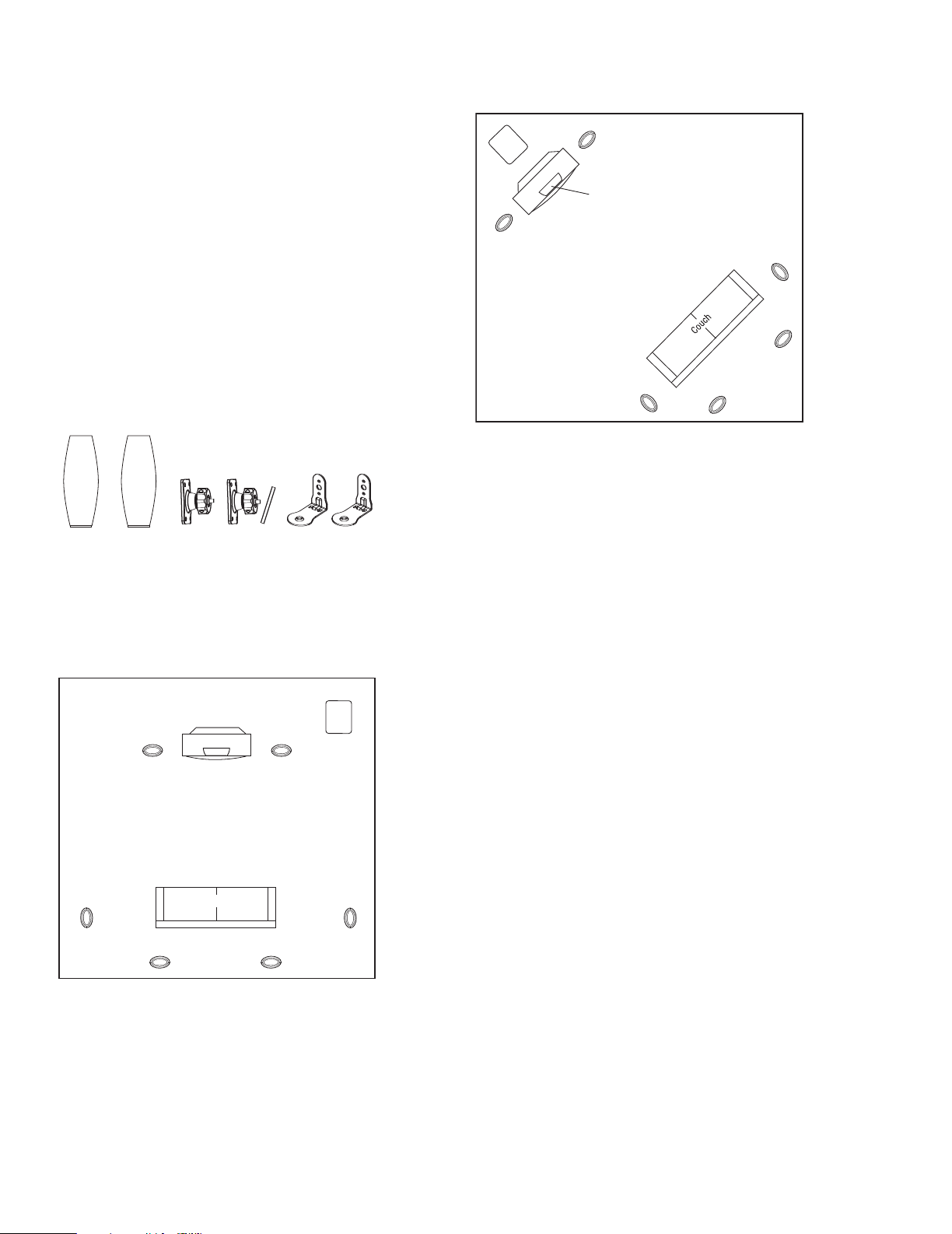
PLANNING YOUR SYSTEM
Before deciding where to best place your speakers, survey your
room and study Figures 1 and 2.
Figure 2. This figure shows an alternative layout, which may be
more suitable for some rooms.
PLACEMENT
NOTE: The CS600SAT can be placed directly on a shelf, or mounted
on a wall using the included wall brackets.
As Left and Right Front Channels
For left and right front channels, place one satellite to the left
and another to the right of the television, as shown in Figure 1.
Since the speakers are magnetically shielded, you can place them
very close to the TV without worrying about the magnetic field
distorting the picture.
Figure 1. In this overhead view of a typical installation, satellite
speakers are used to reproduce sound for the front and surround
channels. The center channel reproduces sound and dialogue.
The powered subwoofer provides bass for effects and music.
As Surround Channels
For left and right surround channels, place one speaker on the left
and another on the right, to the side of or slightly behind the listening
area. The surround speakers should be mounted at a height of
between 5 ft. (1.5m) and 7 ft. (2m).
In 7-channel configurations, place the rear channel(s) behind
the listening position, as shown in Figures 1 and 2.
NOTE: A powered subwoofer will add impact and realism to
both music and film soundtracks. Contact your JBL dealer for
recommendations on subwoofer models for your application.
Mounting on Floor Stands
Optional floor stands are available, should you prefer to place
your CS600SAT satellites on the floor; see your dealer or visit
www.jbl.com for more information.
3
Page 4

Metal bar
Metal bar
A
B
C
Metal bar
W
ALL-MOUNTING THE SATELLITES
he CS600SAT is designed to be mounted on the wall. There is a
T
fixed-mount wall bracket and an adjustable wall bracket provided
or each satellite. Each speaker bracket will require up to four
f
1-1/2"#10
tud. If a wall stud is unavailable, install an anchor appropriate for
s
a 1-1/2"
wood screws; each screw should be fastened to a wall
#10 screw.
NOTE: The customer is responsible for the correct selection
nd use of mounting hardware (available through hardware stores)
a
that will ensure the proper and safe wall-mounting of the speakers.
Fixed-Mount Wall Bracket
tep 1.Mark the positions on the wall where you would like
S
to place the mounting screws.
Step 2. Attach the bracket to the wall using two screws
(not included).
Step 3. Remove the rubber ring on the bottom of the satellite, and
seat the satellite speaker onto the back bracket.
Step 4. Attach 1/4"-20 screw into insert on bottom of speaker
and tighten.
tep 4.Unscrew round collar (C) from bracket (A).
S
Step 5. Screw the ball and shaft assembly (B) to the 1/4"-20 insert on
he back of the satellite (do not use the bottom insert on the speaker).
t
Back out 1/2 of a turn and tighten the nut against the speaker. If the
all and shaft assembly is not backed out before tightening the nut,
b
performing Step 8 below may dislodge the threaded insert in the
speaker housing and permanently damage the speaker.
Adjustable Wall Bracket
Step 1. Remove cap over threaded insert on rear of speaker.
Step 2. Mark the positions on the wall where you would like to
place the mounting screws.
Step 3. Place bracket against the wall and fasten four 1-1/2" #10
wood screws through the bracket’s screw holes into the wall.
If a wall stud is not available, use an appropriate anchor.
Step 6. Attach speaker wire as shown on page 5.
Step 7. Drop round collar (C) over ball and shaft assembly (B) that
is mounted to the speaker with the finished side of the collar facing
the rear of the speaker.
Step 8. Carefully push the ball straight into the socket mounted on
the wall, angle the speaker as desired and tighten the collar using
the enclosed metal bar.
Figure 3. Bracket on wall.
4
Page 5

CONNECTIONS
Receiver or Amplifier
(rear view)
Output
One Channel Shown
Black= –
Red =+
Red =+
Loosen
Terminal
Insert Bare
End; Tighten
Terminal
Black =–
No Stripe =–
S
tripe =+
Speaker Wire
fter placing the speakers, you are ready to connect your system.
A
First, turn off all audio-system power. Use high-quality speaker wire
o make your connections; #18-gauge speaker wire with polarity cod-
t
ing is recommended. For longer distances, #16-gauge or heavier wire
s recommended. The side of the wire with a ridge or other coding is
i
usually considered positive polarity (i.e., +). Also, consult the owner’s
anuals that were included with your amplifier or receiver to confirm
m
connection procedures. Observe polarities when making speaker
onnections, as shown in Figure 4. Connect each + terminal on the
c
back of the amplifier or receiver to the respective + (red) terminal
on each speaker. Connect the – (black) terminals in the same way.
Important!
o not reverse polarities (i.e., + to –, or – to +) when making
D
connections. Doing so will cause poor imaging and diminished
bass response. Be certain that positive and negative wire strands
are completely isolated to avoid short circuits that may damage your
equipment.
NOTE: On certain models using hexagonal terminal nuts, a small
socket wrench is provided to help in properly tightening the terminals.
Hand-tighten only and do not overtighten.
MAINTENANCE AND SERVICE
The enclosure may be cleaned using a soft cloth to remove finger-
rints or to wipe off dust.
p
All wiring connections should be inspected and cleaned or remade
periodically. The frequency of maintenance depends on the metals
nvolved in the connections, atmospheric conditions and other
i
factors, but once per year is the minimum.
If a problem occurs, make sure that all connections are properly
made and clean. If a problem exists in one loudspeaker, reverse the
connection wires to the left and right system. If the problem remains
in the same speaker, then the fault is with the loudspeaker. If the
problem appears in the opposite speaker, the cause is in another
component or cable. In the event that your speaker ever needs
ervice, contact your local JBL dealer or distributor, or visit
s
.jbl.com for a service center near you.
www
Figure 4. Wiring diagram shows polarity connections
for one channel of a home theater system.
5
Page 6

S
Declaration of Conformity
We, Harman Consumer Group International
2, route de Tours
72500 Château du Loir
France
declare in own responsibility that the product described
in this owner’s manual is in compliance with technical
standards:
EN 61000-6-3:2001
EN 61000-6-1:2001
Laurent Rault
Harman Consumer Group International
Ch
âteau du Loir, France 11/06
A. Passive Loudspeakers
Without Power Amplifier
INSTRUCTION SHEET (3/05)
PECIFICATIONS
CS600SAT
Frequency Range (–6dB): 100Hz – 20,000Hz
Recommended
mplifier Power Range:
A
0 – 100 Watts
1
Sensitivity (2.83V @ 1 meter) 88dB
Nominal Impedance: 8Ω
Crossover Frequency: 3.0kHz; 12dB/octave
Midrange Driver: Dual 3-1/2" (89mm) magnetically shielded
High-Frequency Driver: 1/2" (13mm) Titanium-laminate, magnetically shielded
Dimensions (H x W x D): 11-3/8" x 5-5/8" x 3-3/8" (289mm x 131mm x 86mm)
Weight: 3.2 lb (1.5kg)
Features, specifications and appearance are subject to change without notice.
6
Page 7

Page 8

JBL is a trademark of Harman International Industries, Incorporated, registered in
the United States and/or other countries. Pro Sound Comes Home is a trademark
of Harman International Industries, Incorporated.
™
PRO SOUND COMES HOM
®
Harman Consumer Group, Inc., 250 Crossways Park Drive, Woodbury, NY 11797 USA
8500 Balboa Boulevard, Northridge, CA 91329 USA
2, route de Tours, 72500 Château du Loir, France
516.255.4JBL
©
Part No.
(4525) (USA only) www
2006 Harman International Industries, Incorporated. All rights reserved.
406-000-05545-E
.jbl.com
E
 Loading...