

Page 1
Service Manual
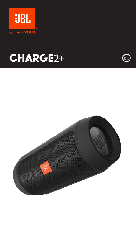
Charge 2 Plus (with SN starting with GG )
Portable Wireless Stereo Speaker with passive bass radiators, 6000 mAh battery for 12 hours of
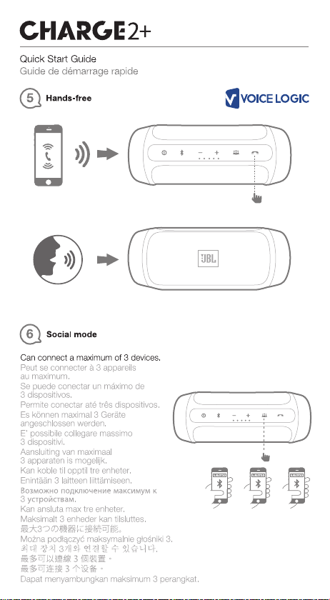
playing time and charging of other devices through USB. Social mode to share music,
microphone for telephone conference use, with echo and noise reduction systems.
CONTENTS
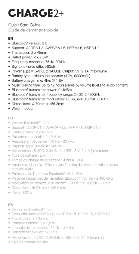
Technical Specifications
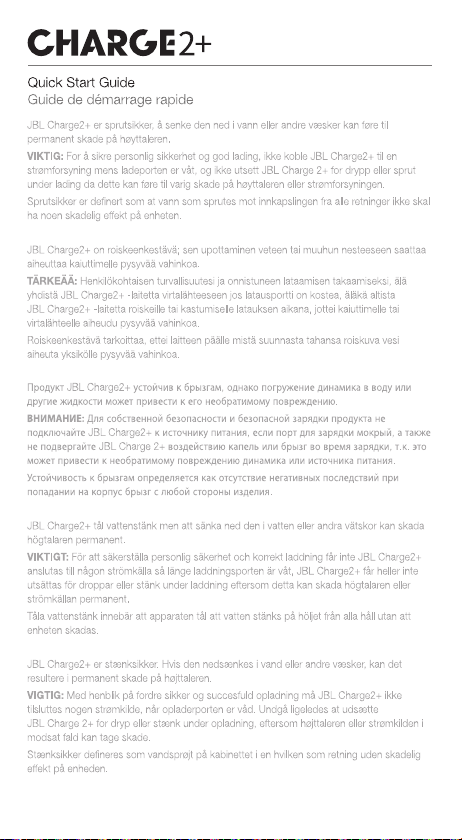
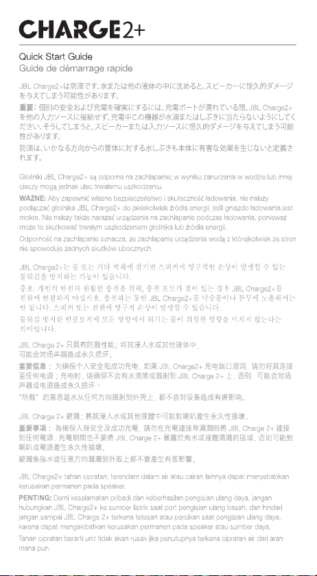
Safety Instruction, Warning & Notes
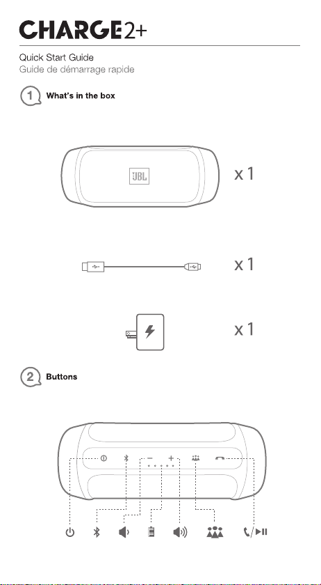
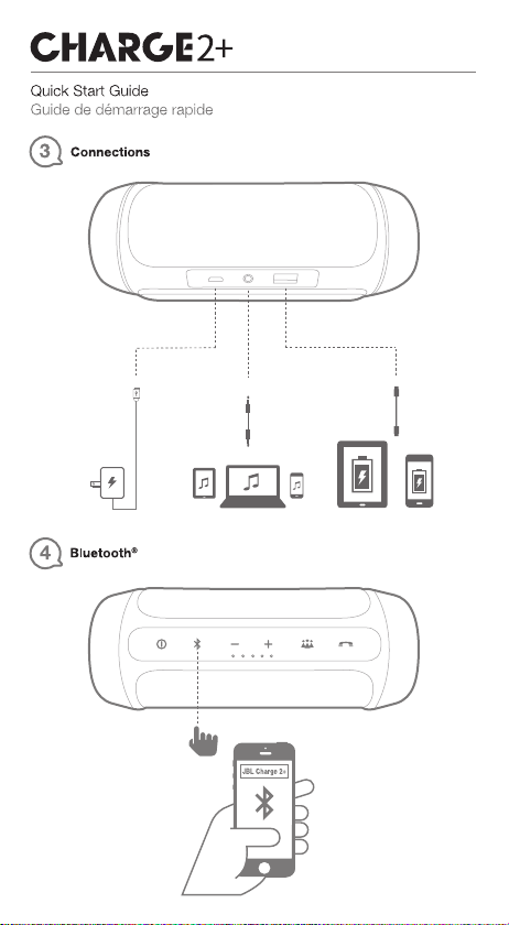
QSG
Set Disassembly Instruction
Set Block Diagram
Schematic Diagrams 31
Set Mechanical Exploded view & Part list 38
Spare Parts List
Packaging Assembly Instruction
Revision List
2
3
6
24
30
35smargaiDtuoyaLBCP
39
41
49
Released by Global Quality SL
harman/kardon, Inc.
Ver. 1.1 10/2015
Page 2
BDS 270 / BDS 570 harman/kardon
Important Safety Instructions
1. Read these instructions.
2. Keep these instructions.
3. Heed all warnings.
4. Follow all instructions.
5. Do not use this apparatus near water.
6. Clean only with a dry cloth.
7. Do not block any ventilation openings.Install in accordance with the manufacturer’s instructions.
8. Do not install near any heat sources such as radiators, heat registers, stoves or other apparatus (including
amplifiers) that produce heat.
9. Do not defeat the safety purpose of the polarized or grounding-type plug. A polarized plug has two blades with one
wider than the other. A grounding-type plug has two blades and a third grounding prong. The wide blade or the
third prong is provided for your safety. If the provided plug does not fit into your outlet, consult an electrician for
replacement of the obsolete outlet.
10. Protect the power cord from being walked on or pinched, particularly at plugs, convenience receptacles and the
point where they exit from the apparatus.
11. Only use attachments/accessories specified by the manufacturer.
12. Use only with the cart, stand, tripod, bracket or table specified by the manufacturer or sold with the
apparatus. When a cart is used, use caution when moving the cart/apparatus combination to avoid
injury from tip-over.
13. Unplug this apparatus during lightning storms or when unused for long periods of time.
14. Refer all servicing to qualified service personnel. Servicing is required when the apparatus has been damaged
in any way, such as power supply cord or plug is damaged, liquid has been spilled or objects have fallen into the
apparatus, or the apparatus has been exposed to rain or moisture, does not operate normally or has been dropped.
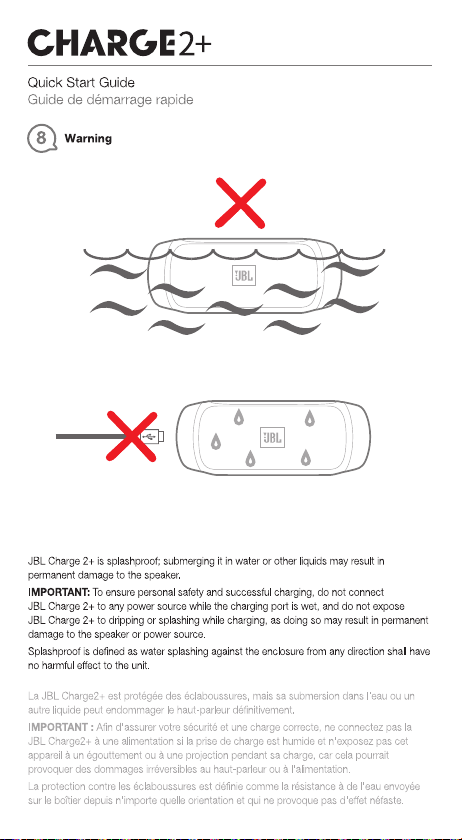
15. Do not expose this apparatus to dripping or splashing and ensure that no objects filled with liquids, such as vases,
are placed on the apparatus.
16. To completely disconnect this apparatus from the AC Mains, disconnect the power supply cord plug from the AC
receptacle.
17. The mains plug of the power supply cord shall remain readily operable.
18. Do not expose batteries to excessive heat such as sunshine, fire or the like.
For Products That Transmit and
Receive RF Energy:
FCC Regulations (USA Only)
FCC Information For Users
This device complies with Part 15 of the FCC Rules. Operation
is subject to the following two conditions: (1) This device
may not cause harmful interference; and (2) this device must
accept any interference received, including interference that
may cause undesired operation.
Radio and Television Interference
This equipment has been tested and found to comply with
the limits for a Class B digital device, pursuant to Part 15
of the FCC Rules. These limits are designed to provide
reasonable protection against harmful interference in a
residential installation. This equipment generates, uses and
can radiate radio frequency energy and, if not installed and
used in accordance with the instructions, may cause harmful
interference to radio communications. However, there is no
guarantee that interference will not occur in a particular
installation. If this equipment does cause interference to radio
or television reception, which can be determined by turning
the equipment off and then on, the user is encouraged to try
to correct the interference by one or more of the following
measures:
• Increase the separation between the equipment and
receiver.
• Connect the equipment to a different outlet so that the
equipment and receiver are on different branch circuits.
• Consult the dealer or an experienced radio/TV technician
for help.
NOTE: Changes or modifications not expressly approved
by Harman could void the user’s authority to operate the
equipment.
For Canadian Model
This Class B digital apparatus complies with Canadian
ICES-003.
Modèle pour les Canadien
Cet appareil numérique de la classe B est conforme à la
norme NMB-003 du Canada.
For Products with Radio Receivers
That Can Use an External Antenna:
CATV or Antenna Grounding
If an outside antenna or cable system is connected to this
product, be certain that it is grounded so as to provide some
protection against voltage surges and static charges. Section
810 of the National Electrical Code, ANSI/NFPA No. 70-1984,
provides information with respect to proper grounding of the
mast and supporting structure, grounding of the lead-in wire
to an antenna discharge unit, size of grounding conductors,
location of antenna discharge unit, connection to grounding
electrodes and requirements of the grounding electrode.
Note to CATV System Installer:
This reminder is provided to call the CATV (cable TV) system
installer’s attention to article 820-40 of the NEC, which
provides guidelines for proper grounding and, in particular,
specifies that the cable ground shall be connected to the
grounding system of the building, as close to the point of
cable entry as possible.
For CD/DVD/Blu-ray Disc™ Players:
IC Statement and Warning (Canada Only)
This Class B digital apparatus complies with Canadian ICES-
003. Cet appareil numérique de la classe B est conforme à la
norme NMB-003 du Canada.
2 of 86
CAUTION
RISK OF ELECTRIC SHOCK. DO NOT OPEN.
THE LIGHTNING FLASH WITH AN ARROWHEAD SYMBOL,
WITHIN AN EQUILATERAL TRIANGLE, IS INTENDED TO
ALERT THE USER TO THE PRESENCE OF UNINSULATED
“DANGEROUS VOLTAGE” WITHIN THE PRODUCT’S
ENCLOSURE THAT MAY BE OF SUFFICIENT MAGNITUDE TO
CONSTITUTE A RISK OF ELECTRIC SHOCK TO PERSONS.
THE EXCLAMATION POINT WITHIN AN EQUILATERAL
TRIANGLE IS INTENDED TO ALERT THE USER TO
THE PRESENCE OF IMPORTANT OPERATING AND
MAINTENANCE (SERVICING) INSTRUCTIONS IN THE
LITERATURE ACCOMPANYING THE PRODUCT.
WARNING: TO REDUCE THE RISK OF FIRE OR ELECTRIC
SHOCK, DO NOT EXPOSE THIS APPARATUS TO RAIN OR
MOISTURE.
Caution:
This product uses a laser system. To prevent direct exposure
to the laser beam, do not open the cabinet enclosure or defeat
any of the safety mechanisms provided for your protection.
DO NOT STARE INTO THE LASER BEAM. To ensure proper use
of this product, please read the owner’s manual carefully and
retain it for future use. Should the unit require maintenance
or repair, please contact your local Harman Kardon service
center. Refer servicing to qualified personnel only.
For Products That Include Batteries:
Instructions for Users on Removal and Disposal of
Used Batteries.
CAUTION
Risk of explosion if battery is incorrectly replaced.
Replace only with the same or equivalent type.
Alkaline batteries are considered nonhazardous.
Rechargeable batteries (i.e., nickel cadmium, nickel metalhydride, lithium and lithium-ion) are considered hazardous
household materials and may pose an unnecessary health
and safety risk.
In the European Union and other locations, it is illegal to
dispose of any battery with household trash. All batteries
must be disposed of in an environmentally sound manner.
Contact your local waste management officials for information
regarding the environmentally sound collection, recycling and
disposal of used batteries.
To remove the batteries from your equipment or remote
control, reverse the procedure described for inserting
batteries in the owner’s manual.
For products with a built-in battery that lasts for the lifetime of
the product, removal may not be possible for the user. In this
case, recycling or recovery centers handle the dismantling of
the product and the removal of the battery. If, for any reason, it
becomes necessary to replace such a battery, this procedure
must be performed by authorized service centers.
Page 3
Some semiconductor (solid state) devices can be damaged easily by static electricity. Such components commonly are called
Electrostatically Sensitive (ES) Devices. Examples of typical ES devices are integrated circuits and some field effect transistors and
semiconductor "chip" components.
The following techniques should be used to help reduce the incidence of component damage caused by static electricity.
1. Immediately before handling any semiconductor component or semiconductor-equipped assembly, drain off any electrostatic charge on
your body by touching a known earth ground. Alternatively, obtain and wear a commercially available discharging wrist strap device,
which should be removed for potential shock reasons prior to applying power to the unit under test.
2. After removing an electrical assembly equipped with ES devices, place the assembly on a conductive surface such as aluminum foil, to
prevent electrostatic charge build-up or exposure of the assembly .
3. Use only a grounded-tip soldering iron to solder or unsolder ES devices.
4. Use only an anti-static solder removal device. Some solder removal devices not classified as "anti-static" can generate electrical charges
sufficient to damage ES devices.
5. Do not use freon-propelled chemicals. These can generate electrical change sufficient to damage ES devices.
6. Do not remove a replacement ES device from its protective package until immediately before you are ready to install it. (Most replacement
ES devices are packaged with leads electrically shorted together by conductive foam, aluminum foil or comparable conductive material.)
7. Immediately before removing the protective material from the leads of a replacement ES device, touch the protective material to the
chassis or circuit assembly into which the device will be installed.
CAUTION :
8. Minimize bodily motions when handling unpackaged replacement ES devices. (Otherwise harmless motion such as the brushing together
or your clothes fabric or the lifting of your foot from a carpeted floor can generate static electricity sufficient to damage an ES devices.
Be sure no power is applied to the chassis or circuit, and observe all other safety precautions.
Each precaution in this manual should be followed during servicing.
Components identified with the IEC symbol in the parts list are special significance to safety . When replacing a component identified with
, use only the replacement parts designated, or parts with the same ratings or resistance, wattage, or voltage that are designated in the
parts list in this manual. Leakage-current or resistance measurements must be made to determine that exposed parts are acceptably
insulated from the supply circuit before retuming the product to the customer.
Page 4
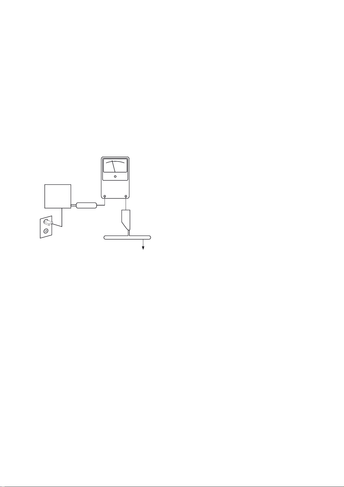
SAFETY PRECAUTIONS
The following check should be performed for the continued
protection of the customer and service technician.
LEAKAGE CURRENT CHECK
Measure leakage current to a known earth ground (water
pipe, conduit, etc.) by connecting a leakage current tester
between the earth ground and all exposed metal parts of the
appliance (input/output terminals, screwheads, metal
overlays, control shaft, etc.). Plug the AC line cord of the
appliance directly into a 120V AC 60Hz outlet and turn the
AC power switch on. Any current measured must not exceed
o.5mA.
Reading should
not be above
0.5mA
Device
under
test
Leakage
current
tester
Test all
exposed metal
surfaces
Also test with
plug reversed
(Using AC adapter
plug as required)
Earth
ground
AC Leakage Test
ANY MEASUREMENTS NOT WITHIN THE LIMITS
OUTLINED ABOVE ARE INDICATIVE OF A
POTENTIAL SHOCK HAZARD AND MUST BE
CORRECTED BEFORE RETURNING THE APPLIANCE
TO THE CUSTOMER.
Page 5
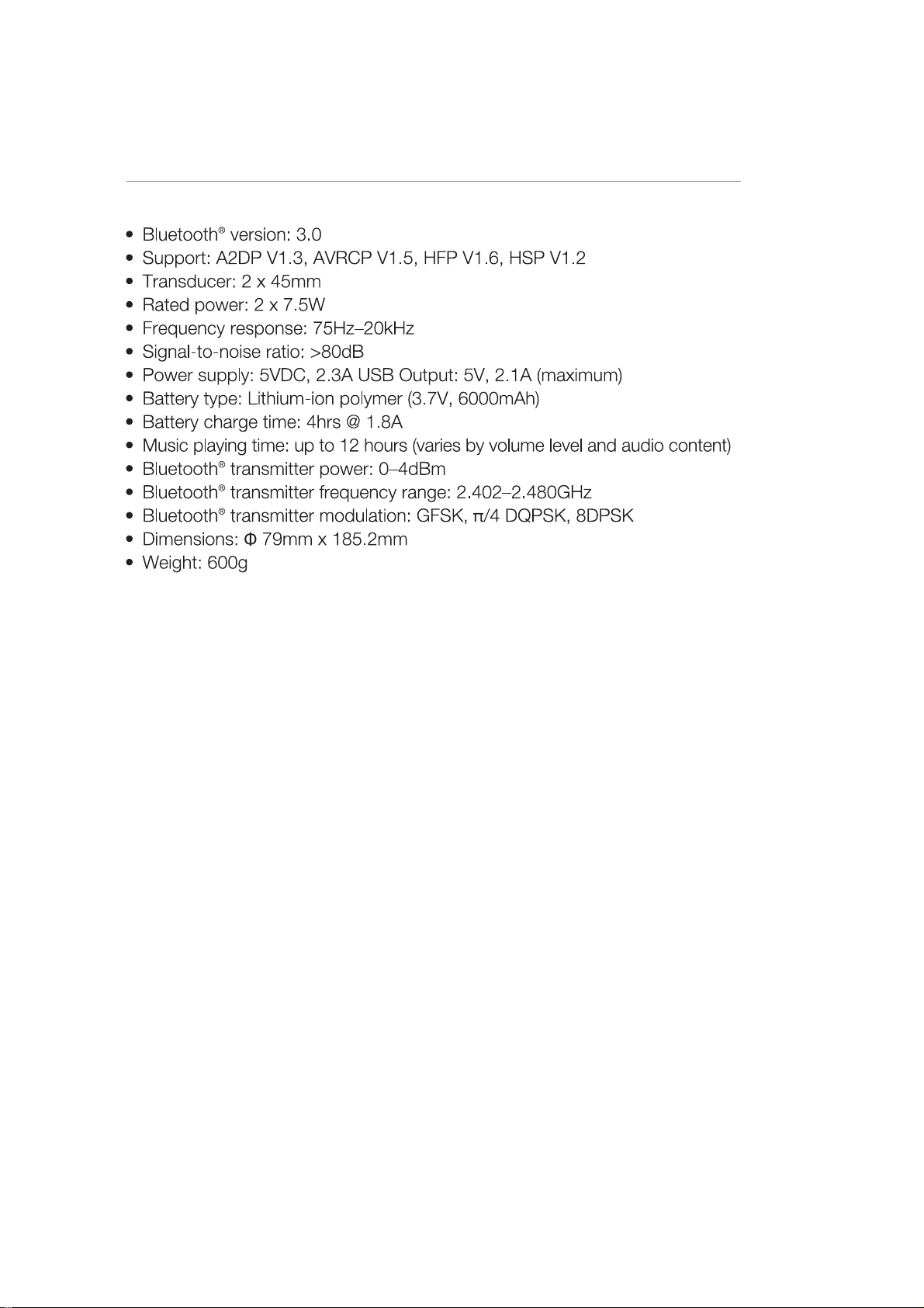
SPECFICATIONS
5
Page 6
Page 7
Page 8
Page 9
Page 10
Page 11
Page 12
Page 13
Page 14
Page 15
Page 16

Page 17

Page 18

Page 19

Page 20

Page 21

Page 22

Page 23

Page 24

Charge2+ Disassembly Instructions
1. Disassemble PE packing˗ķPull the tape which pasted on the PE gently˗ĸTake out the gift
boxDŽ
Gently pull the tape
pasted on PE
2. Tear away sticker˗ķ Tear away the three stickers which pasted on gift box
3. Take out soundbox˗ķOpen gift box, take out soundbox
Page 25

4. Disassemble grille
Disassemble front grille by fixture
Disassemble rear grille by fixture
5. Disassemble top cover & bottom˗ķ Remove 8 screws in top cover& bottom by electric
screwdriver˗
Page 26

6. Disassemble passive radiator
˗
ˈ
˗
screwdriver˗
ķ Remove 8 screws of passive radiator by electric
7. Pull out battery cable
a) Pull out battery cable, MIC cable and antenna˗
b) Disassemble antenna˗
remove antenna
Page 27

˗
8. Disassemble speakers
Remove 8 screws by electric screwdriver˗
Pull out speaker terminals by nipper pliers˗
9. Disassemble button PCBA˗
Tear open rubber˗˄Notice : the rubber cannot be reused˅
Remove 2 screws˗
Page 28

Pry up button-PCBA gently by tweezersˈpull out FFCˈthen take out button-PCBA˗
10. Remove cables˗ķPull out cables of USB PCBA, micro USB PCBA and AUX-in PCBA˗
11. Take out main PCBA
Page 29

12. Remove rubber-feet˄Notice˖the rubber cannot be reused˅
13. Disassemble back cover˗ķRemove 4 screws by electric screw driver˗
14. Disassemble I/O-PCBA, ķRemove 1 screws by I/O-PCBA.
Page 30

Block Diagram
dDŽĚƵůĞ;DϭϱϯͿ
WŽǁĞƌŬĞLJ
ƵdžͺŝŶ
d
ŶƚĞŶŶĂ
DŝĐϭ
h^ƵƉŐƌĂĚĞ
нͲ
/ŶƉƵƚ
sŽůƚĂŐĞ
ĞƚĞĐƚ
ϱs
ŚĂƌŐĞ
ƐƚĂƚƵƐ
ŚĂƌŐĞƌ
DWϮϲϯϳ
ƵĚŝŽ
ĚĞƚĞĐƚ
ĂƚƚĞƌLJ
<ϱϯϱϴ
ŽŶƚƌŽů
ĐŚĂƌŐŝŶŐŐ
ϯϳs
ϲϬϬϬŵ,
ĂƚƚĞƌLJ
ĚĞƚĞĐƚ
KW
ϰϱϭϬ
;dĂŶĚDhͿ
KŶŽĨĨ
ƐǁŝƚĐŚ
KŶKĨĨ
ƐǁŝƚĐŚ
>DϭϯϳϬϬ
ůŝŵŝƚĞƌ
ϰϱϲϬ
ŽŽƐƚ
DW^
DWϯϰϮϴ
>K
KW
/Ϯ
ϭϮs
ϯϯs
ZĞůĞĂƐĞ
ƚƚĂĐŬ
ƚŝŵĞ
WŽǁĞƌ
ĚĞƚĞĐƚ
>Dϯϵϯ
ůĂƐƐ
dWϯϭϯϬ
ϭϲďŝƚ/Ϯ
/K
džƉĂŶĚĞƌ
KŶŽĨĨ
ƐǁŝƚĐŚ
d/
ϳϱtdžϮ
KƚŚĞƌďƵƚƚŽŶƐ
ĂƚƚĞƌLJ
>Ɛ
ϭϮsĨŽƌŵƉůŵϭϯϳϬϬ
Audio Signal:
Power Signal:
Control Signal:
DŝĐƌŽh^
ϭϴϭϬ
ϱ
KŶŽĨĨ
ƐǁŝƚĐŚ
HARMAN INTERNATIONAL. CONFIDENTIAL. COPYRIGHT 2014.
DW^
DWϯϰϮϮ
ϱs
h^ŚĂƌŐĞŽƵƚ
dW^Ϯϱϰϲ
Ϯ
Page 31

SCHEMATICS DIAGRAM
Page 32

Page 33

Page 34

Page 35

LAYOUT DIAGRAM - MAIN BOARD
Page 36

LAYOUT DIAGRAM - KEY BOARD
Page 37

LAYOUT DIAGRAM - I/O BOARD
Page 38

MECHANICAL EXPLODED VIEW
Page 39

JBL Charge 2+ (GG) Spare Part List
90014021107
FRONT ASSY PINK CHARGE 2+ GG(GRILL FRONT+LOGO)
2+3
P/N Description
TT0142002010 Rubber foot pad 142*25*4.5 1
450045 00903 Full range speaker 5
MZ0077015010 LEFT CAP BLACK CHARGE 2+ GG 7
MZ0077015020 LEFT CAP BLUE CHARGE 2+ GG 7
MZ0077015070 LEFT CAP PINK CHARGE 2+ GG 7
MZ0077015030 LEFT CAP RED CHARGE 2+ GG 7
MZ0077015060 LEFT CAP YELLOW CHARGE 2+ GG 7
MZ0077015050 LEFT CAP ORANGE CHARGE 2+ GG 7
MZ0077015080 LEFT CAP TEAL CHARGE 2+ GG 7
MZ0077015040 LEFT CAP GRAY CHARGE 2+ GG 7
000066 06804 1 Passive radiator 8
X10147002010 MAIN HOUSING BLACK CHARGE 2+ GG 10
XT0147002020 MAIN HOUSING BLUE CHARGE 2+ GG 10
XT0147002070 MAIN HOUSING PINK CHARGE 2+ GG 10
XT0147002030 MAIN HOUSING RED CHARGE 2+ GG 10
XT0147002060 MAIN HOUSING YELLOW CHARGE 2+ GG 10
XT0147002050 MAIN HOUSING ORANGE CHARGE 2+ GG 10
XT0147002080 MAIN HOUSING TEAL CHARGE 2+ GG 10
XT0147002040 MAIN HOUSING GRAY CHARGE 2+ GG 10
APA2CHAR25204 KEY PCBA Charge2 11
JL0140002010 Rubber key 140*20*4.5 12
EXM0306030010 Microphone 40dB@2V/2.2K 14
EXA3560003730 Li-ion Battery 3.7V/6000mAH 16
GL0102001010 Battery cover ABS 17
WG0140008010 Grille (back) SECC 18
ASA3CHAR20510 Power Amplifier PCBA Charge2+ 19
ASA5CHAR20510 I/O PCBA 22
HZ0077019010 Bottom cover ABS 23
90014021101 FRONT ASSY BLACK CHARGE 2+ GG(GRILL FRONT+LOGO) 2+3
90014021102 FRONT ASSY BLUE CHARGE 2+ GG(GRILL FRONT+LOGO) 2+3
Position
90014021103 FRONT ASSY RED CHARGE 2+ GG(GRILL FRONT+LOGO) 2+3
90014021106 FRONT ASSY YELLOW CHARGE 2+ GG(GRILL FRONT+LOGO) 2+3
90014021105 FRONT ASSY ORANGE CHARGE 2+ GG(GRILL FRONT+LOGO) 2+3
90014021108 FRONT ASSY TEAL CHARGE 2+ GG(GRILL FRONT+LOGO) 2+3
90014021104 FRONT ASSY GRAY CHARGE 2+ GG(GRILL FRONT+LOGO) 2+3
90007721101 RING ASSY BLK CHARGE 2+ GG (RUBBER RING+RIGHT CAP) 20+21
90007721102 RING ASSY BLU CHARGE 2+ GG (RUBBER RING+RIGHT CAP) 20+21
90007721107 RING ASSY PINK CHARGE 2+ GG (RUBBER RING+RIGHT CAP) 20+21
90007721103 RING ASSY RED CHARGE 2+ GG (RUBBER RING+RIGHT CAP) 20+21
90007721106 RING ASSY YEL CHARGE 2+ GG (RUBBER RING+RIGHT CAP) 20+21
90007721105 RING ASSY ORG CHARGE 2+ GG (RUBBER RING+RIGHT CAP) 20+21
90007721108 RING ASSY TEAL CHARGE 2+ GG (RUBBER RING+RIGHT CAP) 20+21
90007721104 RING ASSY GRY CHARGE 2+ GG (RUBBER RING+RIGHT CAP) 20+21
805004503400S Beauty box 212*166*99 black
819004500900S Instructions
800004500500S Outside box 353*225*216
EWU2100030210 USB Cable L1000MM Type A Plug to Micro B Plug Orange
801004500300S Inner box
ETSC9026BUO0N Power Adapter 100-240V 5V/2.3A GIP CN
ETSU9026BUO0N Power Adapter 100-240V 5V/2.3A GIP US or Japan
ETSE9026BUO0N Power Adapter 100-240V 5V/2.3A GIP EMEA
ETSZ9026BUO0N Power Adapter 100-240V 5V/2.3A GIP Asia
ETSN9026BUO1N Power Adapter IN:100-240V OUT:5V/2.3A GIP
EJP05A3260010 Power Adapter Thailand Plug 2P JQH
EJP05D3260010 Power Adapter Korea Plug 2P JQH
EJP0543260010 Power Adapter SAA Plug 2P JQH
EJP0513260020 Power Adapter EU Pin 2P JQH
EJP0553360020 Power Adapter UK Plug Pin 3P JQH
Page 40

ECE6071000351S Electrolytic capacitor C206
EIL000LM39310S
IC LM393MX-NOPB DUAL COMPARATORS
U14
ECE6071010351S E-CAP SMD 100UF/16V 20% SIZE D (6.3*5.4) C228
ECE3191020350S Electrolytic capacitor C81
EDLS2TWNA021NS LED 0603 white IF=5mA 42-63mcd
EDLS2TRNA021NS LED 0603 red IF=3mA 620-630nm 12.5-24mcd D20
EDACBAV16WS00S Diode BAV16WS 75V 200MA D21,D27,D28,D4,D22
EDG77SVM4510NS Diode SVM1045V 45V MAX_10A D26
EJT1210512000 Terminal socket 5PIN J1
EJT3220201250 Terminal socket 2PIN J11
EJK4100300010 Mini coaxial socket J14
EJCN025R0400 Terminal socket 4PIN J2
EJF30232A0500 FFC socket 32PIN 0.5mm 0.5A-32PLB white J7
EJF0021820500 FFC socket 18PIN 0.5mm 0.5S-CX-18PWB grey J8
EJT1210412001S Terminal socket 5PIN J9
ENLFR100KZ02NS Common mode inductor 10UH 10% 4A L12,L13
EBM42N7002310S N-CH MOSFET SINGLE 240MA 2N7002 60V +/-20V SOT-23 Q10,Q18,Q1
EBMTAR030P02NS P-CH MOSFET 2.5V DRIVE 12V RTR030P02GZTL Q14,Q21
EBMP8TP7425QNS P-CH MOSFET MTP7425Q8 SOP8 14A Q16
EBBTAMEM2310WS N-CH MOSFET 30V 5.8A SOT23 MEM2310 Q17
EBM080AO4420NS N-MOS field effect tube SO-8 ALPH&OMEGA AO4420 9.7A Q20
EBM080AO4420NS N-MOS field effect tube SO-8 AO4420 9.7A Q24
EBMTAR030P02NS P-CH MOSFET 2.5V DRIVE 12V SOT-23 RTR030P02GZTL Q3,Q4,Q5,Q35,Q36
EBM42N7002310S N-CH MOSFET 240MA 2N7002 60V +/-20V SOT-23 Q6,Q12,Q13,Q15,Q22
ERV2N0250NT0FS RES-VARISTOR ESD Protection 3PF 0603 25V SG1,SG2,SG4,SG8
ERV2N0250NT0FS RES-VARISTOR ESD Protection 3PF 0603 25V SG3,SG5,SG6
ESW0611020070 Tact switch 2P
EIP896209A50NS IC ME6209A50P-5V SOT89-3 Low Power Consumption LDO U1
EIOSZBA4580RNS IC BA4580RF OPAMP LOW NIOSE SOP8 U10,U16,U18
EIMTVTCA1116NS IC TCA1116 16-BIT I2C I/O EXPANDER U11
EIOSZLM13700NS IC LM13700A SOP-16 OP AMP U13
D2,D3,D9,D10,D11,D12,D13
,D14,D15,D16,D17,D18,D19
SW1,SW2,SW3,SW4,SW5,
SW6
EIDBA4510FV10S IC OP AMP HP LV DUAL SSOPB8 BA4510FV U15
EIOSX0BU7251NS IC Single operation amplifier BU7251 SSOP5 U17
EIATV0024BITNS IC AK5358AET-E2 ADC 24BIT 96KHZ (HF) U2
EIUQFTPS2546NS IC TPS2546 16P USB CHARGING PORT CONTROLLER U20
EIP896209A33NS IC ME6209A33P-3.3V SOT89-3 LDO U21
EIJ074LVC0410S IC INVERTER SC70-5 SN74LVC1GU04DCKR U3
EIPHT3130D2DNS IC TPA3130D2DAPR POWER AMPLIFIER U7
EIVQFBQ24133NS IC BQ24133RGYR 1.6-MHz QFN-24 U8
EQA1128453220S Quartz crystal AT41CD2 16pF +/-30PPM 11.2896MHz Y1
EKM3CHAR20010 Bluetooth module BM153 Charge 2 Version3.0+EDR
EJF30232A0500 FFC socket 32PIN vertical white 0.5A-32PLB
EJF1021880501 FFC socket 18PIN vertical white 0.5A-18PLB
EJH1231403508 Headphone socket CK3.5-62T-1
EJU5100510060 Micro USB socket 5PIN
EJU5100410010 USB socket SUSB-01-C0-N1-P1
EWA6CHARG0010 Bluetooth Antenna Charge 2
EWF1007090180 FFC cable 18P L70mm
EWF1007090320 FFC cable 32P L70mm
EW34019404000 WIRE 4P UL1007 24AWG L100mm
Page 41

Charge2+
gg y
PackagingAssemblyInstruction
Page 42

Page 43

Page 44

US/Japan/China version
APAC
EMEA version
version
Page 45

Page 46

Page 47

Page 48

Page 49

Revision List
Version 1.0
* Initial release for JBL Charge 2 plus on April. 2015
Version 1.1
* Add some parts for assembled mechanical module & color versions & region versions and,
another power adapter with supplier JQH on Spare Parts List.
 Loading...