

Page 1
p
User’s Guide
harman/kardon
Champagne
950-0010
English
French
German
Italian
S
anish
Page 1
Page 2

Safety Instructions
Please read the following operation precautions before use:
• Read instruc t ions ---A ll th e safety and oper ating inst ruc ti ons shou ld be read thorou ghly bef or e attempt ing t o operate this audio
system.
• Retain instructions for future reference.
• Heed warnin gs --- All warni ngs on this audio syst em and in the operat ing inst ruc tion s should be adher ed to.
• Follow instruc t ions --- A ll operati ng and use instr uc ti ons should be fol low ed.
• TO PREVENT THE RISK OF ELECTRIC SHOCK, DO NOT REMOVE THE COVER (OR BACK). THERE ARE NO USER
SERVICEABLE PARTS INSIDE THIS UNIT, PLEASE RE FER SERVICING TO QUALIFIED HARMAN/ KAR DON
CORPORATION SERVICE PERSO NNEL.
• Do not expose the speakers to liquid or solvent.
• Never rem ove grille c overs in order t o service th e speaker s yst em. The speaker syst em does not contain an y user servic eabl e
parts. Refer all serv icin g to the Harm an/K ardon T echnical Support Group.
• D o not expose the speaker system to temperature or h umidity e xtrem es, direct sunli ght, excessive dust, or vibrations.
• Pl ace the speaker system on a st able, level sur face. Do not drop, apply exc essive force to the controls, or put heavy objects on
top of t h e s peak e r .
• If c lean i ng is required, use a soft dry cloth. If necessary, use a damp cloth without any solvents.
• In order to protect the speaker system, avoid microphone feedback, continu ous output from electronic m usical instruments, or
distorted output from any signal source.
• Do not pl ace the speakers close t o fluorescent light sourc es, or neon light fixtures.
• Althoug h the speakers are magnetical ly shiel ded, keep m agnetic st orage medi a (disks and tapes) at least four inch es from t he
speaker sy st em in order to avoid dat a loss.
• WARNI NG: To reduc e the risk of fire or electri c shoc k, do not expose thi s speaker syst em to rain or moistur e.
Introduction
The HK 695 is the latest innovation from harman/kardon, a long time leader in the manufacture of
high-end component and computer audio systems. harman/kardon’s audio heritage combined with
continual research has provided the unique technologies included in the HK 695.
These technologies include Vmax, a Harman International audio image-processing algorithm that
seamlessly supports both two and four channel sound cards. This audio hologram creates a four
speaker sound field from two speakers through the use of a head related transfer function when used
with a four channel sound card. In addition, the algorithm provides enhanced stereo when used with
a two channel sound card.
The Harman Multimedia Odyssey I transducer is another technology critical to the HK 695. This
unique full range transducer was designed specifically for extremely small speaker enclosures while
providing significant mid bass. In addition to the bass, the small, rigid and light inverted aluminum
cone provides performance that will rival any tweeter used in multimedia speakers today. The result
is a small and elegant satellite speaker that perfectly integrates with the subwoofer while providing
superior midrange and highs.
The Magnum series subwoofer transducer provides deep bass. This Magnum series of woofers are
designed specifically to match with the Harman Multimedia Odyssey I transducers. The same
approach of providing solid bass from a small enclosure guided the development of these Magnum
transducers.
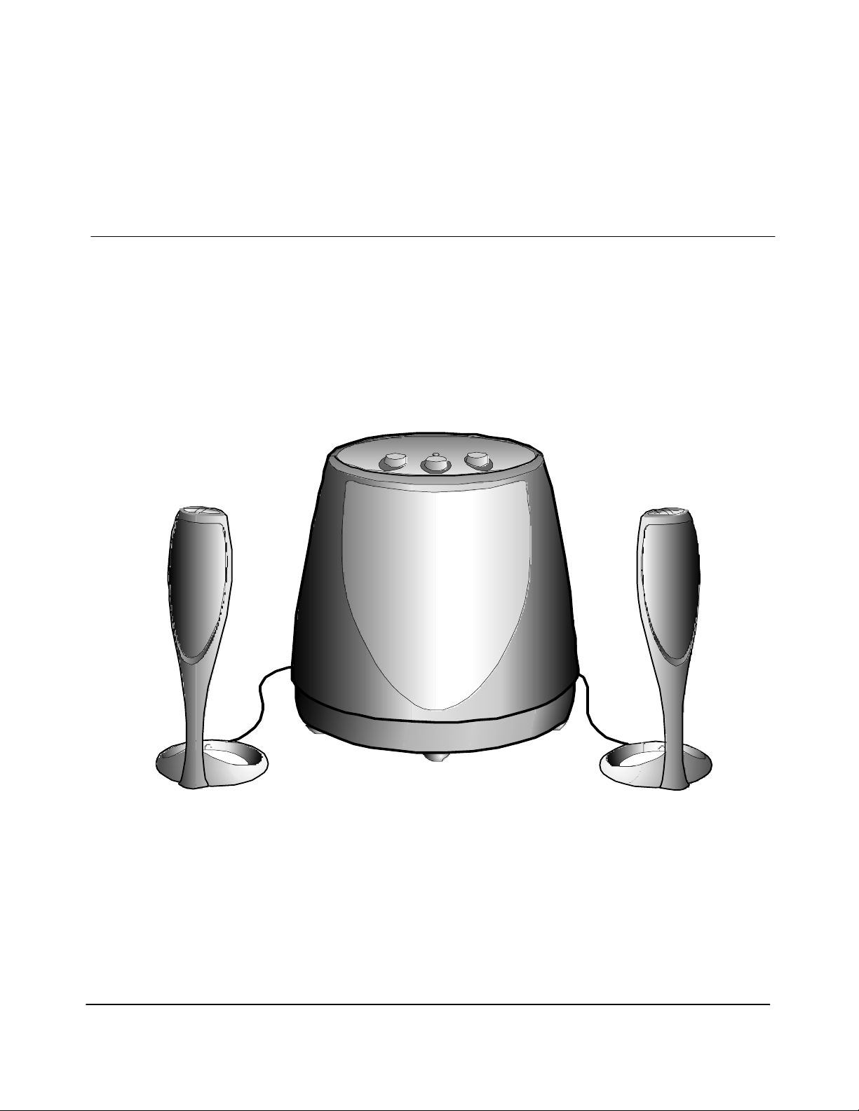
As described in the Using the speaker system section of the user’s guide, the top of the control/right
speaker features
increase or decrease in the system volume. Holding down the appropriate button for more than 0.5
seconds will cause the volume to decrease or decrease rapidly while that button is held down.
Treble, Bass and Surround level adjust knobs are located on top of the subwoofer unit. A system
on/off switch is also provided on the rear of the subwoofer unit. The system includes two desktop
speakers and a subwoofer that can be placed either on the floor or on your desk. Both satellite
speakers and the subwoofer are magnetically shielded to provide the greatest protection against
computer monitor image distortion.
- and + buttons. Briefly pressing the appropriate button will cause a small step
Page 2
Page 3
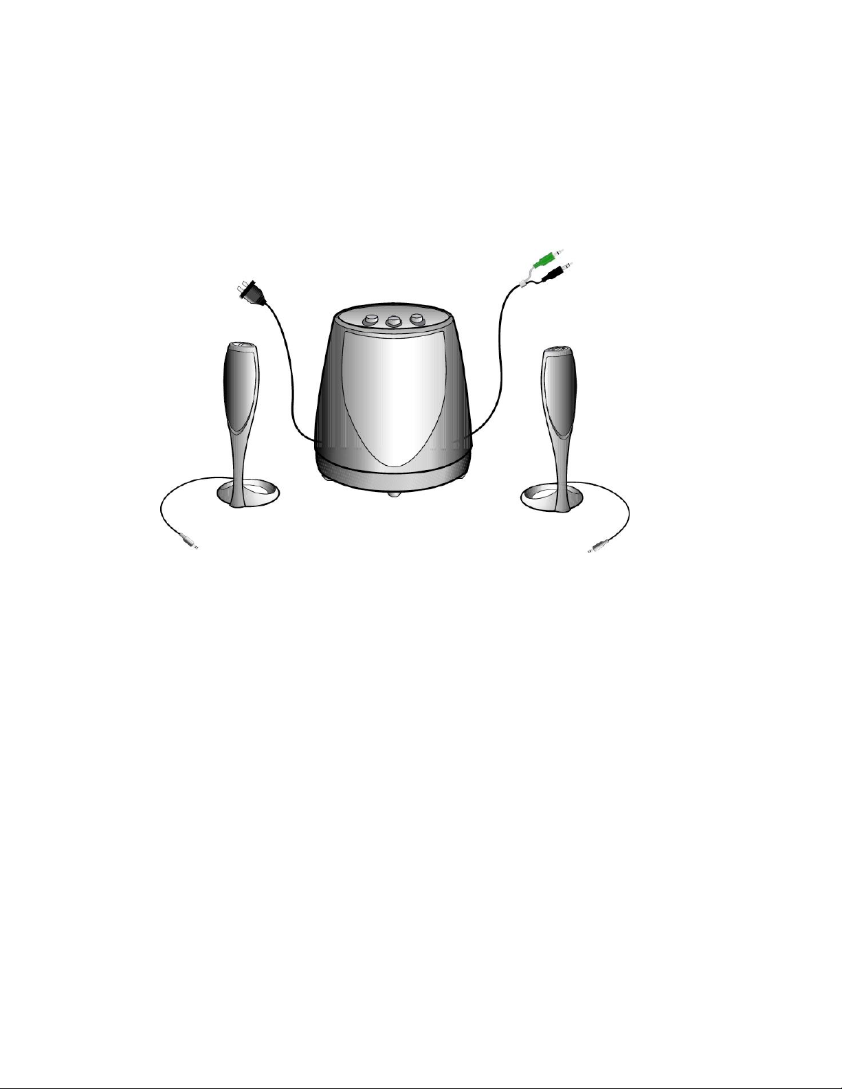
Setup
Carefully unpack your speaker system and identify all components:
• Control/Right Satellite speaker
• Auxiliary/Left Satellite speaker
• Subwoofer with attached power and audio input cables
Connect the speaker system as shown in the Connecting the speaker system to sound card
illustrations. Once the speaker system is prop erly connected, turn on the power switch located on the
rear of the subwoofer.
Step 1 Connecting the speaker system to the computer. If you have an integrated sound solution or
a stereo sound card (as shown on page 4 and 5); connect the green connector from the subwoofer
into the green jack on the computer, the black connector is not used, leave the rubber cap on the
black connector to prevent static from the pin grounding on the system. If you have a multi-channel
sound card (as shown on page 6); connect the green connector from the subwoofer into the green
jack on the computer and connect the black connector from the speaker into the black jack on the
computer. If you have a portable computer (as shown on page 7); connect the green connector from
the subwoofer into the headphone jack on the computer, the black connector is not used, leave the
rubber cap on the black connector to prevent static from the pin grounding on the system.
Step 2 Plug the orange connector from the right/control satellite into the orange jack on the
subwoofe r.
Step 3 Plug the brown connector from the left satellite into the brown jack on the subwoofer.
Step 4 Plug the AC plug into the wall outlet.
Step 5 Turn on the speaker set and adjust the volume accordingly.
Page 3
Page 4

Page 4
Page 5

Page 5
Page 6

Page 6
Page 7

Page 7
Page 8

Placement of speakers
The speakers are magnetically shielded and can be placed close to a computer monitor without
distorting the image. For optimal stereo imaging, separate the speakers from each other by a
distance equal to your distance from the speakers.
The subwoofer’s sound is non-directional; therefore, it does not have to be placed in any particular
relationship to the satellites. The subwoofer is magnetically shielded and can be placed on the
desktop, if desired. If the subwoofer is placed too close to a computer monitor it can cause vibration
on the monitor screen.
Page 8
Page 9

Using the speaker system
On/Off Switch
An on/off switch is located on the rear of the subwoofer.
There is a green LED located on top of each of the two satellite speakers. There is also a green
LED located on the top of the subwoofer. All three LEDs should illuminate when the system is
connected correctly and receiving power.
Turn the speaker off if it will not be used for a long period.
Volume Control
The volume control can be found on the top of the control/right satellite speaker.
Pushing the right + button on the top of this speaker will turn up the volume setting in increments
of 2.0 dB per step. If the button is continuously depressed, after 0.5 seconds the volume level will
constantly increase at a rate of 20 dB per second.
Pushing the left - button on the top of the right speaker will turn down the volume setting in
increments of 2.0 dB per step. If the button is continuously depressed, after 0.5 seconds the
volume level will constantly decrease at a rate of 20 dB per second until the system is muted.
The harman/kardon HK 695 will retain the volume setting when it is turned off so that when the
speaker system is turned back on, it will restore the last volume setting.
Muting
Pushing the left and right buttons simultaneously on the top of the right speaker will mute the
audio. Power will remain on (both speakers’ LED’s remain illuminated). When muted, pushing
either the left button or the right button, or both buttons simultaneously will restore volume to the
level prior to the activation of the mute function.
Page 9
Page 10

Controls on the Subwoofer
There are three tone and effects level knobs located on the top of the subwoofer. They control Bass,
Treble and Surround.
Bass - Turn the knob marked Bass clockwise to increase the subwoofer level or counterclockwise to
decrease the subwoofer level.
Treble – Turn the knob marked Treble clockwise to increase the treble level or counterclockwise to
decrease the treble level.
Surround - Turn the knob marked Surround clockwise to increase the surround level or
counterclockwise to decrease the surround level. Turning this knob all the way counterclockwise will
defeat the surround mode.
Diagnostics
In order to facilitate optimal system setup, a diagnostic system has been built in to the harman/kardon
HK 695. If you are having trouble getting sound out of your system, or are not confident that your
setup is optimal, use these system diagnostics to configure your harman/kardon HK 695.
Disconnect all speaker cables from the sound card. To test the front speaker channel, plug the green
connector into the diagnostic jack on the rear of the subwoofer. This will generate a test tone. This
tone will sweep from 40Hz to 400Hz. As the frequency of the tone increases, the sound will transition
from the Subwoofer to the satellites, then start over again.
Page 10
Page 11

The diagnostic test can also be used to test the rear speaker channel input by plugging in the black
connector into the diagnostic jack on the rear of the subwoofer. The surround level may need to be
adjusted. (Test tone may sound different due to the surround characteristics of speaker system).
When you have finished the test, unplug the connector from the ‘DIAG’ jack and plug the audio
connector back into the correct soundcard output jack. Review the user setup if necessary on pages
3 thru 7.
While the speaker system is in the diagnostic mode, the + and - controls will control the volume of the
diagnostics tone.
If the test tone was heard from all speakers, your HK 695 is working correctly. If not, see the
troubleshooting section for detailed troubleshooting techniques.
Troubleshooting
SYMPTOM
No sound from
Speakers
POSSIBLE
PROBLEM
No power to unit.
SOLUTION
Make sure wall power
out l e t or po w e r st r ip
has power. Make
sure all switches for
outlet/power strip are
on and that all
switches for speaker
system are on.
Toggle the power
switch.
Replace the fuse.
The fuse holder is on
the back of the
subwoofer between
the power cord
connector and the
power switch. Use a
screwdriver to turn a
quarter turn in the
direction indicated by
the arrow. A spare
fuse was supplied
with the product
attached to the AC
power cord. See the
back of the subwoofer
for a description of the
fuse.
NOTE
Check green power
LED on the sub. Are
the LED’s on? If the
sub’s led is not on,
power is not getting to
your speaker system.
Try the solutions
shown.
WARNING!
Unplug the speaker
system from the
electrical outlet before
replacing the fuse
Page 11
Page 12

Distort io n (stati c ,
crackling or hissing
sounds)
Is the control/right
satellite of your HK
695 plugged in
correctly?
Volume level may be
set low or muted.
Noise may be caused
by interf erence from
the monitor.
Ensure that the
control speaker
connector is pushed
in properly.
Remove the control
/right speaker
connector from the
subwoofer, then reconnect this cable
ensuring that the
connector is pushed
in properly.
Increase volume level
on control/right
speaker.
Check volume level
and mute setting in
Windows Volume
Control.
Turn monitor off to
see if noise is
eliminated. Move
speaker cables farther
away from monitor.
There is an LED
located in the top of
each of t h e two
satellite speakers.
These should both be
lit. If they are, your
speakers are both
plugged in correctly.
Assuming power has
been verified, engage
the self-test by
removing the audio
connector(s) from the
soundcard output(s)
and connecting it to
the ‘DIAG’ jack.
Speaker is being
overdriven by an
amplified audio
source.
Volume level on
sound ca rd may be
too high.
Sound c ar d or au dio
source mat erial may
be cause of problem.
Ensure that speaker is
connected to the
appropriate
receptacle. Check
color-coding on
connectors when
making connections.
Make sure that all
signal cables are
inser t ed snu gl y in t o
receptacles.
Check volume of
sound card via
Windows Volume
Control.
Check speakers with
another audio source.
Disconnect speaker
input cable (green
connector) from
sound card and plug
into CD ROM
headphone jack.
If static is eliminated,
troubleshoot the
soundcard.
Page 12
Page 13

Are the speaker
system mode settings
optimized?
Set each of the three
knobs (treble, Sub
level, surround) on top
of the subwoofer back
the their center/
nominal positions.
Too much bass or
treble.
Subwoofer emits a
loud hum or bu zzi n g
noise.
Speaker system emits
a loud hum or bu zz i n g
noise when used with
a stereo only (not
multichannel)
soundcard.
Speaker system
experiences radio
frequency interference
or picks up a radio
station
Bass/Treble level is
set too high
Input cables not
plugged in properly
The redundant rear
(black) audio
connector is not
protected by the
rubber cover and is
touching the computer
case.
Input cable may be
pic ki n g up
interference
Turn B as s/Treble
dow n or r et ur n t heir
settings to the center
position.
Chec k i n pu t cable
connection
Replace the rubber
cover or otherwise
insulate the rear audio
connector so it cannot
contact an y metallic
surfaces.
Wrap up excess input
cable in order to make
as short as possible
Purchase a ferrite
clamp and attach over
input cable. A clamp
can be purchased at
your local electronics
store
Page 13
Page 14

Specifications
Manufacturer Harman International
Model Number HK 695
Drivers (satellite) Two Odyssey
Drivers (subwoofer) One 5.25 inch woofer
Power (satellite) 6 watts per satellite at 1% THD
Power (subwoofer) 28 watts at 1% THD
Crossover Frequency (subwoofer) 180 Hz
Dimensions
Width:
Satellite 3.5 inches
Subwoofer 11.75 inches
Depth:
Satellite 5.75 inches
Subwoofer 11.75 inches
Height:
Satellite 11.5 inches
Subwoofer 13 inches
Inp ut Impeda nce 5-10 k O h m
Signal-to-Noise ratio >70dB
Frequency Response 35 – 20 kHz
Input Sensitivity 300-400 mV rms for rated
power output
Fuse type Rad io Shack 27 0-106 2 or E q i v .
NOTE: Before replacing fuse, remove AC power
plug from the wall outlet. To replace fuse, twist
fuse cap counterclockwise with a standard
flathead screwdriver. The fuse cap is spring
loaded and will pop out.
USA/Canada Power 120 volts, 60Hz AC
Maximum Power Consumption 120 watts
UL/CUL/CE Approved
Regulatory
FCC Statement and Warning
This equipment has been tested and found to comply with the limits for a Class B digital device,
pursuant to Part 15 of the FCC rules. These limits are designed to provide reasonable protection
against harmful interference in a residential installation. This equipment generates, uses and can
radiate radio frequency energy and, if not installed and used in accordance with the instructions, may
cause harmful interference to radio communications. However, there is no guarantee that
interference will not occur in a particular installation. If this equipment does cause harmful
interference to radio or television reception, which can be determined by turning the equipment off
and on, the user is encouraged to try to correct the interference by on or more of the following
measures:
a) Re-orient or relocate the receiving antenna.
b) Increase the separation between the equip ment and receiver.
c) Connect the equipment to an outlet on a circuit different from that to which the receiver is
connected.
d) Consult the dealer or an experienced radio/TV technician for help.
MODIFICATIONS NOT EXPRESSLY APPROVED BY THE MANUFACTURER COULD VOID THE
USER AUTHORITY TO OPERATE THE EQUIPMENT UNDER FCC RULES.
Page 14
 Loading...