

Page 1
CBT1000 and CBT1000E
Bracket Installation Guide
Rev C
CBT1000
CBT1000E
Page 2
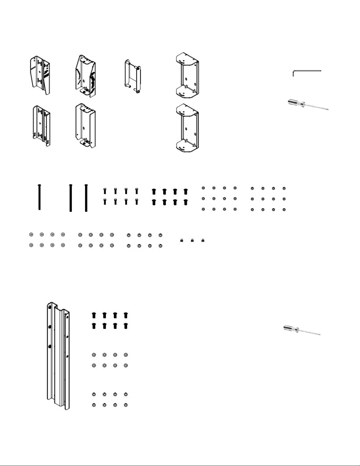
Hardware Included with CBT1000:
WALL
BRACKETS
M6 x 115 mm
PAN HEADS
SPEAKER
BRACKETS
M6 x 125 mm
PAN HEADS
ARM
LINK
M6 x 20 mm
SOCKET HEADS
SWIVEL
BRACKETS
M8 x 20 mm
PAN HEADS
Tools Required:
4 Bracket Parts for UPPER
←
Mounting Position on
Cabinet (when set for 0° or
for down-tilting)
3 Bracket Parts for LOWER
←
Mounting Position on
Cabinet (when set for 0° or
for down-tilting)
Note: When setting system for UP tilting, the UPPER and LOWER
parts get reversed on the cabinet -- see instructions.
M6
FLAT WASHERS
M6 SPLIT
LOCK WASHERS
M6 Hex Wrench
#2 Phillips Head Screwdriver
M6 RUBBER
WASHERS
M8
FLAT WASHERS
M8 SPLIT
LOCK WASHERS
Hardware Included with CBT1000E:
M8 x 20 mm PAN HEADS
M8 FLAT WASHERS
M8 SPLIT LOCK WASHERS
M6
CAP NUTS
Tools Required:
#2 Phillips Head Screwdriver
2
Page 3
Instructions for CBT 1000 Alone (without 1000E):
The BRACKET ASSEMBLY consists of 2 pieces of SPEAKER BRACKETS (the parts that mount on the
speaker), 2 pieces of WALL BRACKETS (the parts that mount on the wall), 2 pcs of SWIVEL BRACKETS
(which get added to the SPEAKER BRACKETS if utilized for horizontal swivel/pan aiming capability), and an
ARM LINK (which is utilized for the larger tilt angles).
1) RUN WIRING -- Run the wiring from the power amplier to the location desired for mounting the JBL
CBT Loudspeakers. Note: Connect wire to speaker terminals at a point in the installation process when
convenient for your installation circumstances.
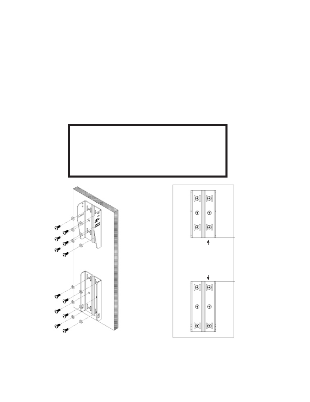
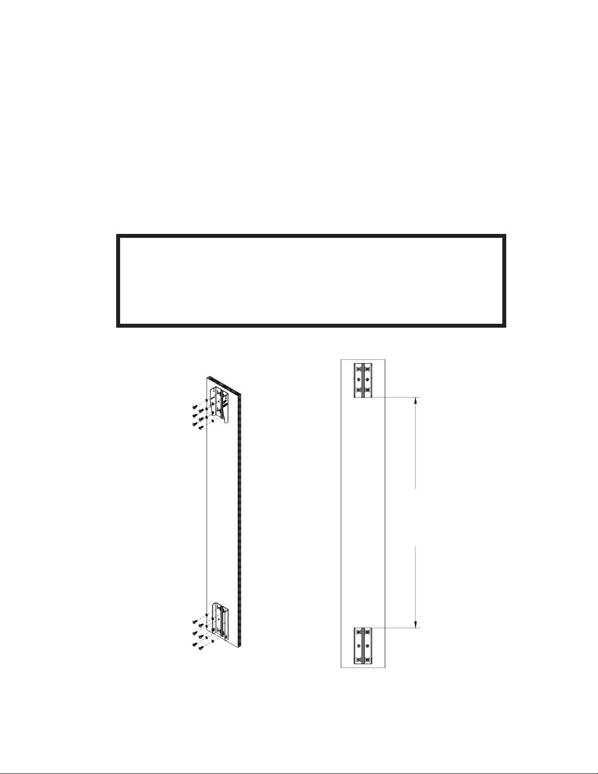
2) ATTACHING WALL BRACKET TO WALL -- Using a level to ensure that the WALL BRACKET is straight,
secure the WALL BRACKET to the wall. Be sure to use the appropriate wall anchors for attaching the
bracket. Use as many of the screw holes as possible for maximum integrity and safety.
CAUTION: Installation must be done by
qualied persons using safe rigging standards.
The installer is responsible for proper selection and use of
mounting hardware to properly and safely wall-mount the
speakers.
(Drawings show upper
and lower bracket
orientation as set for
down-tilt or 0°. Wall
brackets to be reversed
in location and ipped for
up-tilt applications (see
further instructions).
Hardware attaching WALL BRACKET to wall is not included.
Utilize proper hardware for particular wall structure.
Spacing:
181 mm (7-1/8”) for Down-Tilt
197 mm (7-3/4”) for Up-Tilt
Spacing needed between upper and lower
WALL BRACKET parts with CBT1000 depends on
whether speaker will be set with down-tilt or up-tilt.
3
Page 4
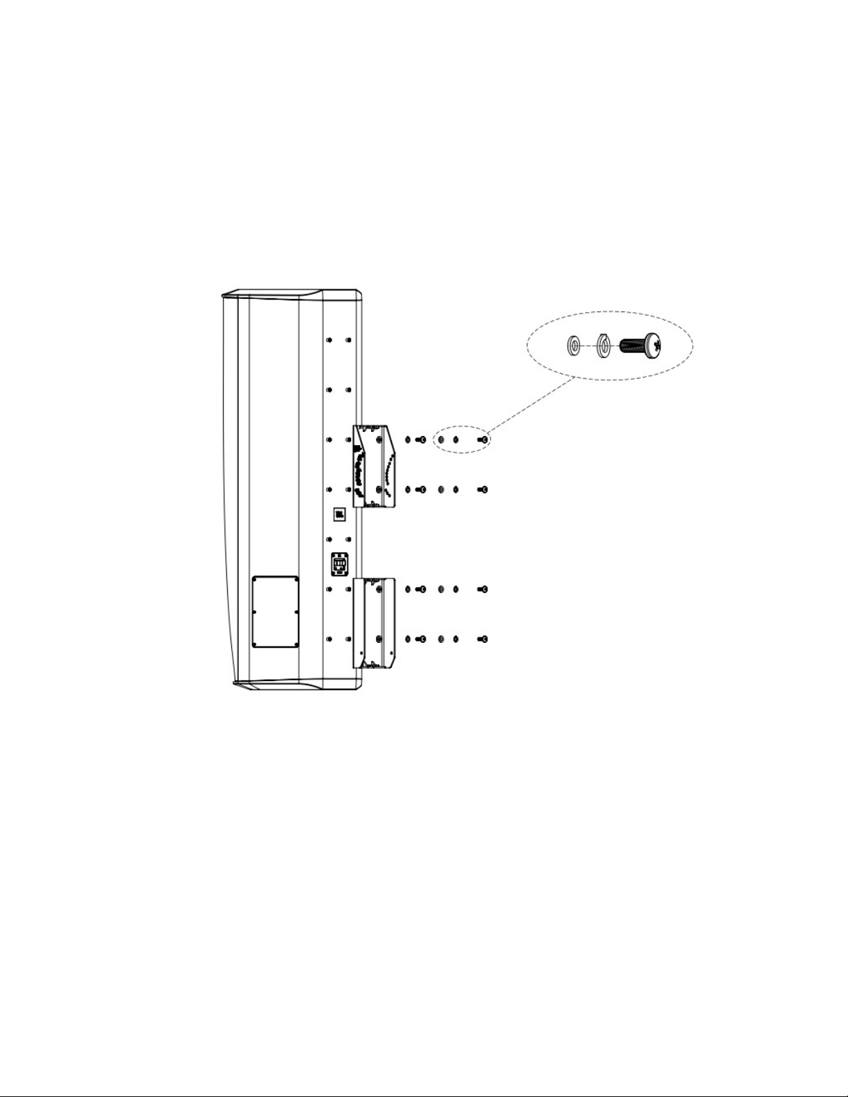
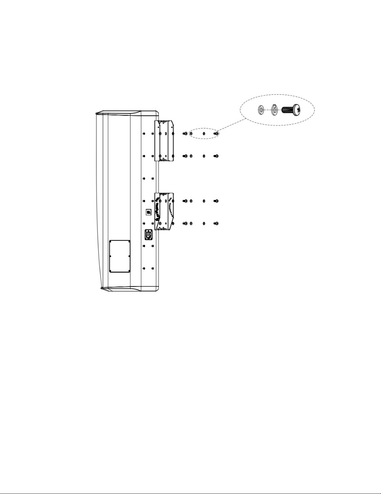
3) ATTACH SPEAKER SIDE OF BRACKET TO SPEAKER
Mount the SPEAKER BRACKET (2 pcs) to the speaker with the provided M8 x20 mm pan-head bolts, in
the locations shown and in the orientation shown in the diagram below.
Option 3a) CBT 1000 with No Swivel (for Down-Tilt Capability [or 0° tilt] and No Horizontal Swivel/Pan).
8 PLACES:
M8
FLAT WASHER
M8 SPLIT
LOCK WASHER
M8 x 20 mm
PAN HEAD
BOLT
Down-tilt range 0° to -15°
4
Page 5
Option 3b) CBT 1000 with Up-Tilt Capability -- No Horizontal Swivel/Pan
8 PLACES:
M8
FLAT WASHER
M8 x 20 mm
PAN HEAD
BOLT
M8 SPLIT
LOCK WASHER
Up-tilt range 0° to +15°
5
Page 6
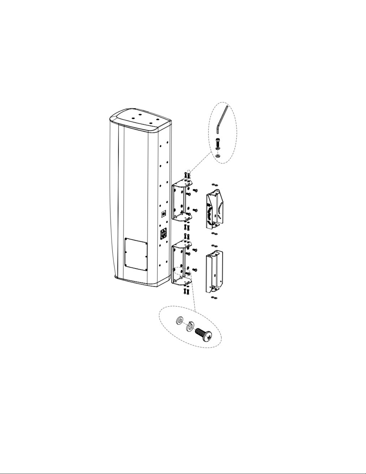
Option 3c) CBT1000 Mounting with Down-Tilt Capability and SWIVEL BRACKET
(for Horizontal Swivel/Pan aiming capability)
8 PLACES:
M6 Hex Wrench
M6 x 20 mm
SOCKET HEAD BOLT
M6 SPLIT
LOCK WASHERS
M6 FLAT WASHERS
M8
FLAT WASHER
M8 SPLIT
LOCK WASHER
Down-tilt range 0° to -15°
8 PLACES:
M8 x 20 mm
PAN HEAD
BOLT
6
Page 7
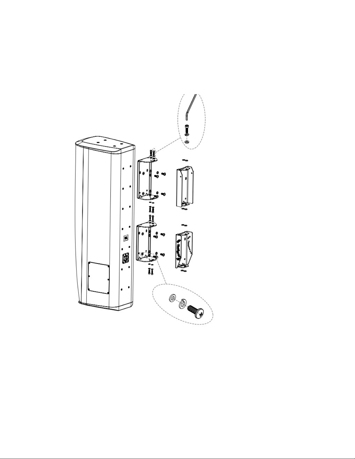
Option 3d) CBT1000 Mounting with Up-Tilt Capability and SWIVEL BRACKET
(for Horizontal Swivel/Pan aiming capability)
8 PLACES:
M6 Hex Wrench
M6 x 20 mm
SOCKET HEAD BOLT
M6 SPLIT
LOCK WASHERS
M6 FLAT WASHERS
Up-tilt range 0° to +15°
M8
FLAT WASHER
M8 SPLIT
LOCK WASHER
8 PLACES:
M8 x 20 mm
PAN HEAD
BOLT
7
Page 8
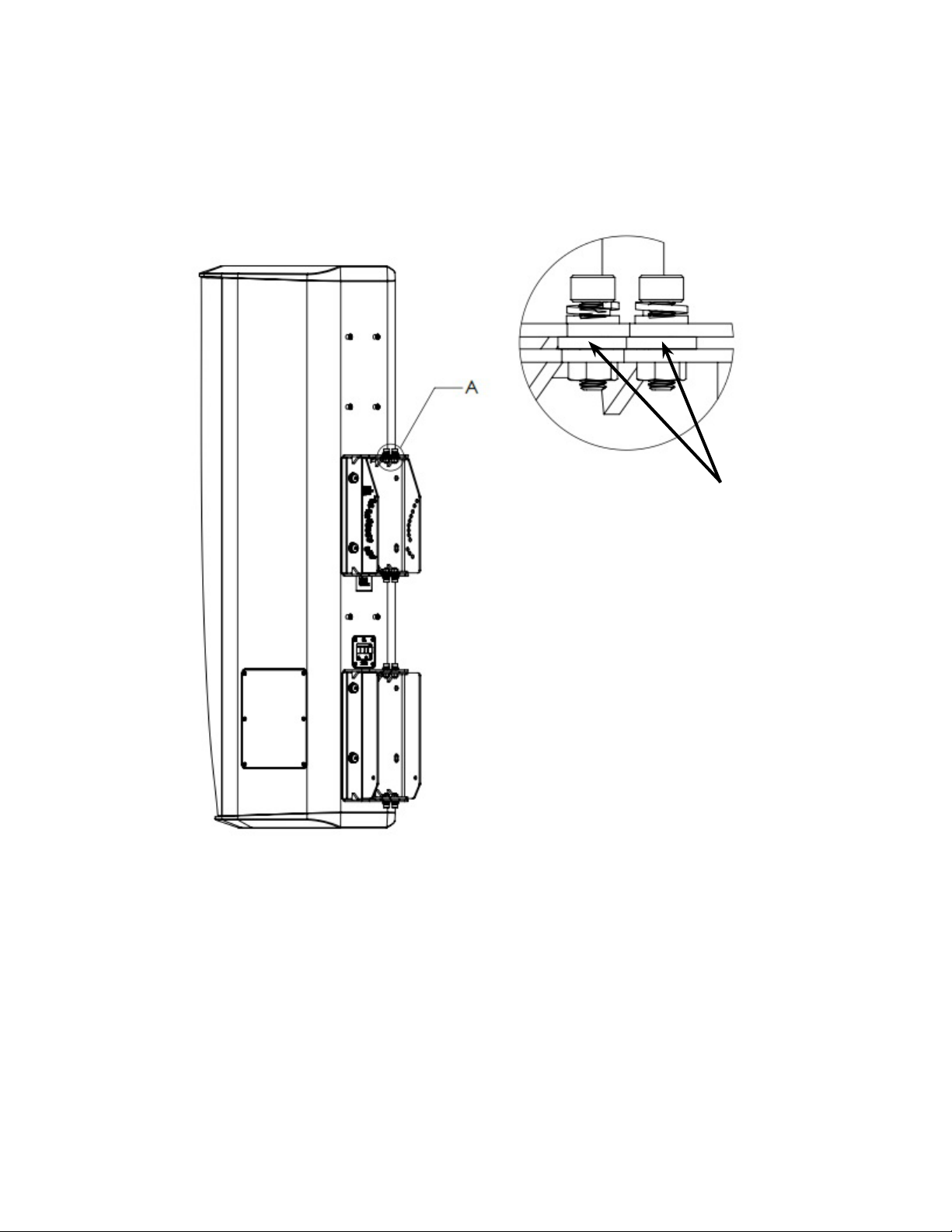
For Options 3c and 3d (congurations that include the SWIVEL BRACKET), place RUBBER
WASHERS as shown when using SWIVEL BRACKET:
RUBBER WASHERS to be placed
between SWIVEL BRACKET and
SPEAKER BRACKET
4) Jump to page 15 for CBT 1000 tilt angling instructions.
8
Page 9
Instructions for CBT 1000+1000E System:
The BRACKET ASSEMBLY consists of 2 pieces of SPEAKER BRACKETS (the parts that mount on the
speaker), 2 pieces of WALL BRACKETS (the parts that mount on the wall), 2 pcs of SWIVEL BRACKETS
(which get added to the SPEAKER BRACKETS if utilized for horizontal swivel/pan aiming capability), and an
ARM LINK (which is utilized for the larger tilt angles).
1) RUN WIRING -- Run the wiring from the power amplier to the location desired for mounting the JBL
CBT Loudspeakers. Note: Connect wire to speaker terminals at a point in the installation process when
convenient for your installation circumstances.
2) ATTACHING WALL BRACKET TO WALL -- Using a level to ensure that the WALL BRACKET is straight,
secure the WALL BRACKET to the wall. Be sure to use the appropriate wall anchors for attaching the
bracket. Use as many of the screw holes as possible for maximum integrity and safety.
CAUTION: Installation must be done by qualied persons
using safe rigging standards.
The installer is responsible for proper selection and use of mounting hardware
to properly and safely wall-mount the speakers.
(Drawings show upper
and lower bracket
orientation as set for
down-tilt or 0°. Wall
brackets to be reversed
in location and ipped for
up-tilt applications (see
further instructions).
Hardware attaching WALL BRACKET to wall is not
included. Utilize proper hardware for particular wall
structure.
Spacing:
1200 mm (47-1/4”) for Down-Tilt
1216 mm (47-7/8”) for Up-Tilt
Spacing needed between upper and lower
WALL BRACKET parts with CBT1000 and
CBT1000E depends on whether speaker will be set
with down-tilt or up-tilt
9
Page 10

3) ATTACHING COUPLER PLATE -- Connect the CBT 1000 and CBT 1000E together by attaching
COUPLER PLATE to bottom four (4) insert points of the CBT 1000 and to top four (4) insert points of
CBT 1000E using 8 pcs M8 x 20 PAN-HEAD PHILLIPS BOLTS with LOCK WASHERS and FLAT
WASHERS. Tighten.
IMPORTANT: WHEN THE CBT 1000E IS LOCATED ON THE TOP VERSUS ON THE BOTTOM
The diagram below shows the COUPLER PLATE attachment method for when the CBT 1000 is on
the top and the CBT 1000E on the bottom. For utilizing with the CBT 1000E on top and the CBT
1000 on the bottom, the depth of the cabinets are different at the junction between them, so it is
necessary to use the optional MTC-CBT-OS3 Offset Bracket (which is part of the CBT1K-ACC1
kit). See Appendix A for attaching together in this orientation utilizing the MTC-CBT-OS3 bracket.
8 PLACES:
M8
FLAT WASHER
LOCK WASHER
M8 x 20 mm
PAN HEAD
BOLT
M8 SPLIT
Hint: One strategy for orienting speakers for
attaching the COUPLER PLATE is to place
both speakers on a non-scratching oor
surface on their sides.
10
Page 11

4) ATTACH SPEAKER SIDE OF BRACKET TO SPEAKER
Option 4a) CBT 1000+1000E System with No Swivel
(for Down-Tilt Capability [or 0° tilt] and No Horizontal Swivel/Pan)
8 PLACES:
M8
FLAT WASHER
LOCK WASHER
M8 x 20 mm
PAN HEAD
BOLT
M8 SPLIT
Down-tilt range 0° to -5.25°
11
Page 12

Option 4b) CBT1000+1000E System with Up-Tilt Capability
(No Horizontal Swivel/Pan)
8 PLACES:
M8
FLAT WASHER
M8 x 20 mm
PAN HEAD
BOLT
M8 SPLIT
LOCK WASHER
Up-tilt range 0° to +5.25°
12
Page 13

Option 4c) CBT1000+1000E System with Down-Tilt Capability and Horizontal Swivel/Pan
8 PLACES:
M8 SPLIT
LOCK WASHER
M8
FLAT WASHER
M8 x 20 mm
PAN HEAD
BOLT
SWIVEL BRACKET attaches to speaker
via M8 x 20 mm PAN HEAD BOLTS (with
lock washers and atwashers).
SPEAKER BRACKET attaches to
SWIVEL BRACKET via M6 x 20 SOCKET
HEAD BOLTS inserted from the top and
bottom of the SWIVEL BRACKET, with
RUBBER WASHERS between the two
brackets.
See pages 6 and 7 for detailed drawings
of SPEAKER BRACKET / SWIVEL
BRACKET connection (as shown on CBT
1000 alone).
Down-tilt range 0° to -5.25°.
Horizontal ±45° Swivel (Pan)
13
Page 14

Option 4d) CBT1000+1000E System with Up-Tilt Capability and Horizontal Swivel/Pan
M8
FLAT WASHER
M8 SPLIT
LOCK WASHER
8 PLACES:
M8 x 20 mm
PAN HEAD
BOLT
SWIVEL BRACKET attaches to speaker
via M8 x 20 mm PAN HEAD BOLTS (with
lock washers and atwashers).
SPEAKER BRACKET attaches to
SWIVEL BRACKET via M6 x 20 SOCKET
HEAD BOLTS inserted from the top and
bottom of the SWIVEL BRACKET, with
RUBBER WASHERS between the two
brackets.
See pages 6 and 7 for detailed drawings
of SPEAKER BRACKET / SWIVEL
BRACKET connection (as shown on CBT
1000 alone).
Up-tilt range 0° to +5.25°.
Horizontal ±45° Swivel (Pan)
14
Page 15

The following instructions apply to both the CBT1000 by itself and
to the CBT 1000+1000E System.
(For simplicity, drawings are shown with CBT1000 only.)
5) SLIDE SPEAKER WITH SPEAKER BRACKET ONTO WALL BRACKET
Make sure the PIVOT BOLT is installed in-place in the SPEAKER BRACKET. The PIVOT BOLT
ASSEMBLY consists of the M6 x 125 mm bolt with lock washer and at washer on the head and secured
in place with at washer, lock washer and M6 cap nut. IMPORTANT: Leave the nut loose (do not tighten).
Slide the speaker forward so that the SPEAKER BRACKET engages into the WALL
BRACKET, dropping the PIVOT BOLT ASSEMBLY into the hook slot of the WALL BRACKET.
For Down-Tilt or 0°
For Up-Tilt
For Down-Tilt or 0° Tilt
Hook Slot
Install PIVOT BOLT before dropping
speaker into WALL BRACKET
Install PIVOT BOLT before dropping
speaker into WALL BRACKET
Hook Slot
Drop PIVOT BOLT into
hook slot of WALL BRACKET
Bolt Installed
Bolt Installed
Drop PIVOT BOLT into
hook slot of WALL BRACKET
15
Page 16

6) SET THE TILT ANGLE
6a) For Setting Shallow Tilt Angles (0° to -3° for CBT1000; 0° to -0.9° for CBT1000+1000E System),
do NOT use ARM LINK.
Slide the M6 x 125 mm BOLT into labeled hole for desired down-tilt angle. Use LOCK WASHER
and FLAT WASHER on head and FLATWASHER, LOCK WASHER, and CAP NUT on end of bolt.
For clarity, shown without loudspeaker (or
SWIVEL BRACKET, if utilized), and shown with
brackets in the down-tilt orientation.
M6 CAP NUT
M6 LOCK WASHER
M6 FLAT WASHER
ARM LINK is not to be used for tilt angles from 0° to 3°
(CBT1000) or 0° to 0.9° (CBT 1000 + 1000E System)
See full size Tilt Angle Settings Diagram for
detail of markings and settings
M6 FLAT WASHER
M6 LOCK WASHER
M6 x 125 mm BOLT
CBT 1000: 0°
CBT 1000 + 1000E: 0°
Use Points “C”
CBT 1000: 1°
CBT 1000 + 1000E: 0.3°
CBT 1000: 2°
CBT 1000 + 1000E: 0.6°
16
CBT 1000: 3°
CBT 1000 + 1000E: 0.9°
Page 17

6b) For Setting Larger Tilt Angles (-4° to -15° for CBT1000; -1.25° to -5.25° for CBT1000+E
System), Use ARM LINK.
Loosely attach the ARM LINK to the WALL BRACKET using the M6 x 115 mm bolt in hole A or B
(depending on desired tilt angle -- refer to TILT ANGLE SETTINGS DIAGRAM). Use LOCK WASHER
and FLAT WASHER on head and FLATWASHER, LOCK WASHER, and CAP NUT on end of bolt.
IMPORTANT: Do not tighten yet (leave loose).
Attach the other end of ARM LINK to SPEAKER BRACKET. Slide the M6 x 125 mm BOLT into
labeled hole for desired down-tilt angle through the holes in the lower end of the ARM LINK. Use
LOCK WASHER and FLAT WASHER on head and FLATWASHER, LOCK WASHER, and CAP NUT
on end of bolt.
For clarity, shown without SPEAKER BRACKET
Tighten all bolts.
M6 x 115 mm BOLT
(and SWIVEL BRACKET, if used), and shown
with brackets in the down-tilt orientation.
M6 x 125 mm BOLT
M6 LOCK WASHER
M6 LOCK WASHER
M6 FLAT WASHER
M6 FLAT WASHER
M6 LOCK WASHER
M6 CAP NUT
M6 FLAT WASHER
ARM LINK is to be used for tilt angles greater than 3° (CBT 1000)
or 0.9° (CBT 1000 + 1000E System). ARM LINK is to be installed
to WALL BRACKET rst before setting angle.
17
Page 18

Tilt Angle Settings Diagram
+
+
Shown set in the 13° tilt setting for CBT1000, or 4.5°
tilt setting for CBT 1000 + 1000E System
(Marked A-13° in black and A-4.5° in orange, so other
end of LINK ARM is at Point “A”)
18
Page 19

See full size Tilt Angle Settings Diagram on previous
page for detail of markings and settings
ARM LINK Not Utilized
“System” = CBT 1000 + 1000E
+
= Bolt Setting Location(s)
+
Use
Point “C”
CBT 1000: 0°
System: 0°
CBT 1000: 1°
System: 0.3°
ARM LINK Utilized
Use
Point “B”
CBT 1000: 4°
System: 1.25°
+
+
+
+
CBT 1000: 2°
System: 0.6°
“System” = CBT 1000 + 1000E
+
+
CBT 1000: 5°
System: 1.75°
+
+
CBT 1000: 6°
System: 2.0°
+
CBT 1000: 3°
System: 0.9°
+
= Bolt Setting Location(s)
Use
Point “A”
Use
Point “A”
+
+
CBT 1000: 7°
System: 2.5°
+
CBT 1000: 12°
System: 4.0°
+
+
CBT 1000: 8°
System: 2.75°
+
CBT 1000: 13°
System: 4.5°
+
CBT 1000: 9°
System: 3.0°
+
19
+
++
+
CBT 1000: 14°
System: 5.0°
+
CBT 1000: 10°
System: 3.5°
+
+
+
CBT 1000: 11°
System: 3.75°
+
CBT 1000: 15°
System: 5.25°
+
+
Page 20

7) SETTING HORIZONTAL SWIVEL (PAN) AIMING – With the 8 M6 x 20 mm SOCKET HEAD
swivel screws loose (4 on top bracket and 4 on bottom bracket), set the horizontal swivel (pan)
aiming angle. Tighten all 8 swivel screws.
Once all components have been
installed, use HEX WRENCH to
loosen SWIVEL BRACKET and
the speaker will be able to pan to
+45°.
2 M6 x 20 mm SOCKET BOLTS
2 M6 x 20 mm SOCKET BOLTS
2 M6 x 20 mm SOCKET BOLTS
2 M6 x 20 mm SOCKET BOLTS
20
Page 21

BRACKET PARTS DIMENSIONAL DIAGRAMS
WALL BRACKET TOP/BOTTOM SECTIONS
48
50
[2.0]
[1.9]
196
[7.7]
M6 Bolt
Clearance
Holes
Narrow
Pole-Strap
Slots
Wide
Pole-Strap
Slots
184
[7.3]
104
[4.1]
24
[1.0]
50
[2.0]
29
[1.1]
209
[8.2]
Center Recessed
Channel for
Improved
Pole-Mount
Stability
21
Dims in mm [in]
Page 22

SPEAKER BRACKET TOP/BOTTOM SECTIONS
208
[8.2]
70
[2.8]
111
[4.4]
M8 Bolt Clearance
Holes
172
[6.8]
45
[1.8]
4 x M6 Threaded Inserts
44
[1.7]
M6 Bolt Clearance Holes
228
[9.0]
70
[2.8]
111
[4.4]
44
[1.7]
200
[7.9]
73
[2.9]
4 x M6 Threaded Inserts
M6 Bolt Clearance Hole
Dims in mm [in]
22
Page 23

SWIVEL BRACKET TOP/BOTTOM SECTIONS
70
[2.8]
87
[3.4]
220
[8.7]
113
[4.4]
123
[4.8]
[2.1]
70
[2.8]
180
[7.1]
53
82
[3.2]
37
[2.2]
87
[3.4]
239
[9.4]
110
[4.3]
120
[4.7]
81
[3.2]
57
[2.2]
23
206
[8.2]
82
[3.2]
Dims in mm [in]
Page 24

LINK ARM
90
[3.6]
96
[3.8]
103
[4.1]
33
[1.3]
172
[6.8]
24
Page 25

APPENDIX A - MTC-CBT-OS2 Offset Bracket
MTC-CBT-OS3 Offset Bracket must be used when the CBT 1000E (extender) is located on the top
versus on the bottom of the CBT 1000 (full-range speaker).
The optional MTC-CBT-OS3 bracket is part of the CBT1K-ACC1 kit.
Hardware Included with MTC-CBT-OS3:
MTC-
CBT-OS3
BRACKET
Tool Required:
M8 x 20 mm
PAN HEAD
BOLTS
M6
FLAT WASHERS
M6 SPLIT
LOCK WASHERS
#2 Phillips Head
Screwdriver
25
Page 26

1) Attach MTC-CBT-OS3 to bottom 4
inserts of CBT 1000E using M8 PAN
HEAD BOLTS with LOCKWASHERS
AND FLATWASHERS
2) Attach top of COUPLER PLATE to
MTC-CBT-OS3 BRACKET by inserting
bolts through holes in MTC-CBT-OS3
BRACKET (3 on left side; 3 on right
side) and thread into captured nuts in
COUPLER PLATE
(6 places)
3) Attach bottom of COUPLER
PLATE to CBT 1000 via the normal
method, using M8 PAN HEAD BOLTS
with LOCK WASHERS and FLAT
WASHERS
(4 places)
4) Insert 2 bolts through middle holes
in the back panel of the COUPLER
PLATE and thread into captured
nuts at the bottom of MTC-CBT-OS3
bracket.
M8 x 20 mm
PAN HEAD BOLTS with
LOCK WASHERS and
FLAT WASHERS
6 PLACES:
3 on left side,
3 on right side
M8 x 20 mm
PAN HEAD BOLTS with
LOCK WASHERS and
FLAT WASHERS
4 PLACES
Make sure all bolts are tight.
M8 x 20 mm
PAN HEAD BOLTS with
LOCK WASHERS and
FLAT WASHERS
6 PLACES
26
Page 27

Completed Assembly
27
Page 28

JBL Professional
8500 Balboa Blvd.
Northridge, CA 91329
U.S.A.
CBT1000 Brkt RevC
10/17
 Loading...