

Page 1

TM
Professional-Grade Automotive Component Speaker System C508GTi C608GTi
Owner’s Manual · Einbauanleitung · Guide d’utilisation · Manual de uso · Manuale Utente · Brugsvejledning
PRO POWER
Page 2

TM
Professional-Grade Automotive Component Speaker System Owner’s Manual C508GTi C608GTi
PRO POWER
Page 3

Important: Installation of automotive
stereo components can require extensive
experience performing a variety of mechanical and electrical procedures. Although
these instructions explain how to install a
GTi component system in a general sense,
they do not show the exact installation
method for your particular car. If you don’t
feel you have the necessary tools or experience, ask your authorized JBL car audio
dealer about professional installation
options.
Warning: Playing loud music in your automobile can permanently damage your hearing as well as hinder your ability to hear traffic. We recommend listening at low volume
while driving. JBL accepts no liability for
hearing loss, bodily injury or property damage resulting from use or misuse of this
product.
A Note About System Performance
For the best performance possible, the GTi
components should be used with a twochannel amplifier with output power of at
least 50W RMS per channel. The passive
crossover contains impedance compensation circuitry and has been computer-optimized for the flattest possible frequency
response with the tweeter flush-mounted,
on-axis with the listener. The combined
response of the speakers and passive
crossover constitutes a 4th-order LinquitzRiley acoustic alignment and cannot be
duplicated with any electronic crossover
currently available for car audio use. Consequently, bi-amping a GTi component system
with an electronic crossover is not recommended.
Speaker Placement
Figures 1–4 show possible speaker
placements in the order of most desirable to
least desirable. Kick-panel mounting will
provide the best staging and imaging in
most vehicles.
TWEETER
on dash
WOOFER
in factorydoor location
TWEETER
on kick panel
WOOFER
in factorydoor location
TWEETER
and
WOOFER
on kick panel
WOOFER
in factorydoor location
TWEETER
in high/forward
location on door
Fig 1
Fig 3
Fig 2
Fig 4
Figure 1.
Mounting the woofer and tweeter in the kick
panels
Figure 2.
Mounting the woofer in the door and the tweeter
in the kick panel
Figure 3.
Mounting the woofer and tweeter in the doors
Tweeter Installation
Figure 4.
Mounting the woofer in the door and the tweeter
in the dash
–
+
Figure 5.
Surface-mounting the tweeter:
first push in (1), then turn (2)
Figure 6.
Flush-mounting the tweeter:
first push in (1), then turn (2)
02
The Official Brand of Live Music
–
+
Page 4
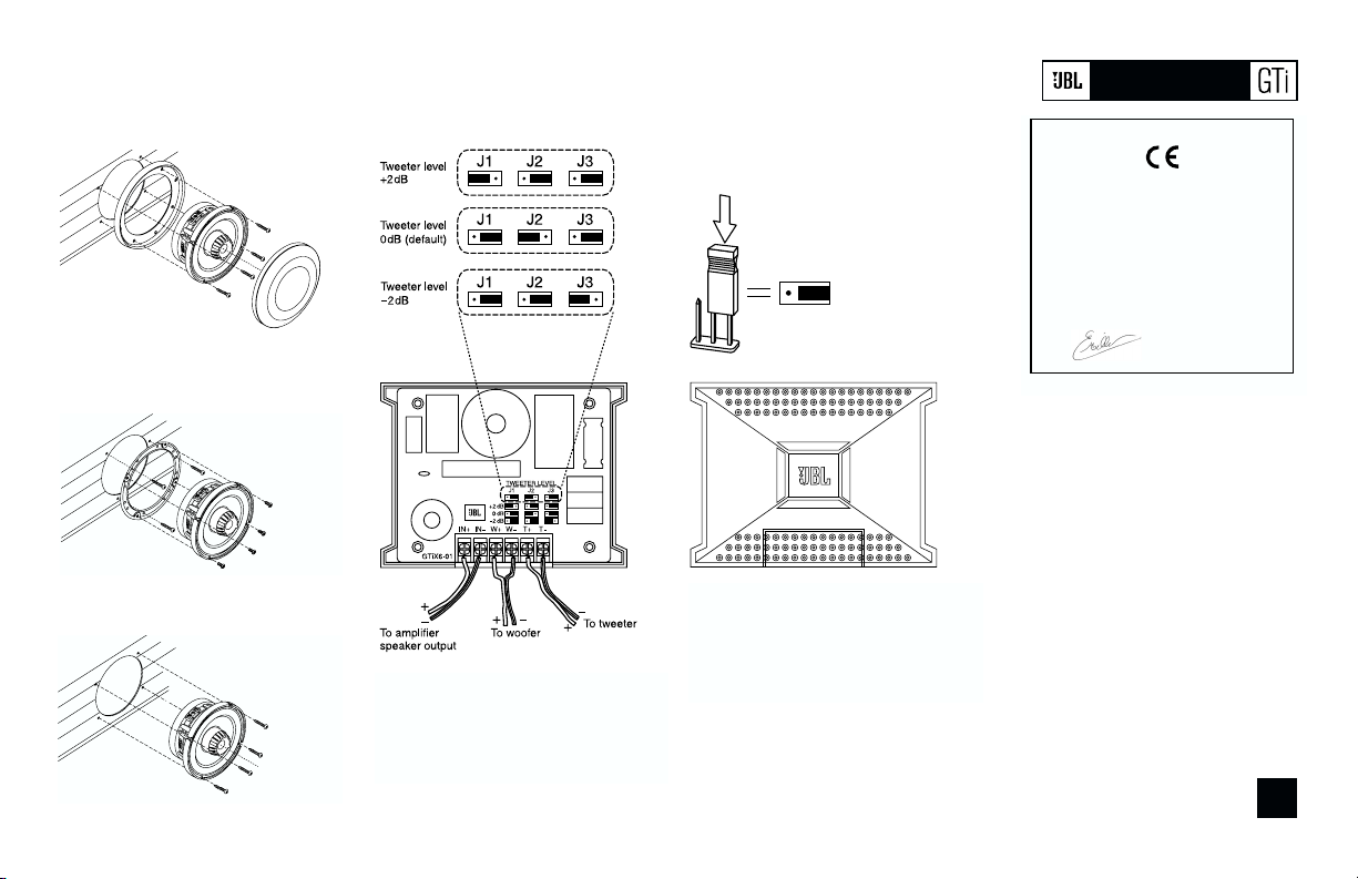
Woofer Installation
Figure 7.
Mounting the C508GTi or C608GTi woofer
where there is no factory speaker location.
To mount the C508GTi in factory locations, omit
the grille and grille tray.
Figure 8.
Mounting the C608GTi woofer in standard 5-1/4"
holes (in many Japanese and American automobiles)
Figure 9.
Mounting the C608GTi woofer in 165mm holes
(in many European and American automobiles)
Electrical Connections and Crossover Adjustments
Figure 10.
Connecting the speakers and the amplifier to
the crossover
Figure 11.
Adjust the crossover using the jumpers
provided
03
PRO POWER
TM
DECLARATION OF CONFORMITY
We, Harman Consumer International
2, route de Tours
72500 Chateau-du-Loir
France
declare in own responsibility, that the products
described in this owner’s manual are in compliance
with technical standards:
EN 50081-1:1992
EN 50082-1:1997
Emmanuel Millot
Harman Consumer International
Chateau-du-Loir, France 7/01
Page 5

JBL Consumer Products • 250 Crossways Park Drive, Woodbury, NY 11797
1-800-336-4JBL (4525) www.jbl.com
©2001 JBL, Incorporated • JBL is a registered trademark of JBL, Incorporated
Part No. C508/C608GTiOM7/01
Specifications
C508GTi C608GTi Tweeter
5-1/4" Professional-grade 6-1/4" Professional-grade
automotive component automotive component
speaker system speaker system
Power handling (peak) 500W 600W n/a
Power handling (RMS) 125W 150W n/a
Frequency response 58Hz – 21kHz 50Hz – 21kHz n/a
Nominal impedance 4 ohms 4 ohms n/a
Sensitivity (2.83V/1m) 88dB 89dB n/a
Crossover 4th-Order Linkwitz-Riley Acoustic, 3500Hz, 24dB/octave n/a
Cut-out diameter 4-5/8" (118mm) 5-1/8" (131mm) 1-3/4” (45mm)
Mounting depth 2-3/8" (61mm) 2-11/16" (69mm) 1” (25.4mm)
Thiele and Small Parameters
Revc 3.00 3.50 3.14
Levc 0.16 0.25 0.01
Sd 0.0086 0.0117 0.0006
BL 6.00 6.69 2.22
Vas 3.34 7.90 0.0016
Cms 322.0 405.0 31
Mms 12.07 18.21 0.46
Mmd 11.61 17.48 0.452
Fs 80.7 58.61 1320
Qms 6.51 9.01 1.8
Qes 0.51 0.52 2.463
Qts 0.47 0.50 1.04
Top-plate thickness 0.2” (5.08mm) 0.25” (6.35mm) n/a
Voice-coil length 0.5” (12.7mm) 0.65” (16.51mm) n/a
Voice-coil diameter 2” (50.8mm) 2” (50.8mm) 1” (25.4mm)
Xmax 1/8” (3.44mm) 1/8” (3.44mm) n/a
Page 6

PRO POWER
TM
Composants audio type professionnel pour véhicule. Guide d’utilisation C508GTi C608GTi
Page 7

Important : L’installation de composants
audio dans un véhicule demande une certaine expérience des procédés mécaniques et
circuits électriques, et la présente notice ne
traite que des modalités générales d’installation de ces composants GTi. Elle n’entre
pas dans le détail d’éventuelles procédures
spécifiques à votre véhicule. Si vous pensez
manquer d’expérience et d’outils, demandez
assistance à votre revendeur JBL agréé.
Avertissement : Reproduire de la musique
à volume élevé dans un véhicule peut
générer des troubles irréversibles de l’ouïe
et couvrir les bruits de circulation. Il est donc
recommandé de régler le volume sur un
niveau modéré pendant la conduite. JBL
décline toute responsabilité en cas de troubles auditifs, blessures corporelles ou
dégâts matériels susceptibles d’être
imputés à une utilisation, à bon ou mauvais
escient, de ce produit.
Note sur les performances du système
Pour l’obtention des meilleures performances, ces haut-parleurs GTi doivent être
utilisés avec un amplificateur bicanal d’une
puissance de sortie d’au moins 50W RMS
par canal. Le filtre passif intègre un circuit
de compensation de l’impédance et a été
optimisé pour fournir la réponse en fréquence la plus plate possible lorsque le tweeter
est encastré et dans l’axe de la position
d’écoute. Le résultat combiné est un alignement acoustique Linquitz-Riley ordre 4. La
bi-amplification au moyen d’un filtre électronique pour applications embarquées supplémentaire n’est donc pas conseillée.
Emplacement des haut-parleurs
Les illustrations 1–4 montrent les installations possibles, par ordre de décroissance
en terme de qualité de diffusion sonore. Un
montage dans les panneaux latéraux situés
sous la planche de bord donne généralement le meilleur résultat dans la plupart des
véhicules.
TWEETER
on dash
WOOFER
in factory-
door location
TWEETER
on kick panel
WOOFER
in factory-
door location
TWEETER
and
WOOFER
on kick panel
WOOFER
in factory-
door location
TWEETER
in high/forward
location on door
Fig 1
Fig 3
Fig 2
Fig 4
Figure 1.
Montage du woofer et du tweeter dans le
panneau bas de caisse avant
Figure 2.
Montage du woofer dans la portière et du
tweeter dans le panneau avant
Figure 3.
Montage du woofer et du tweeter dans les
garnitures de portières
Installation des tweeters
Figure 4.
Montage du woofer dans la portière et du
tweeter dans la planche de bord
–
+
Figure 5.
Pose en surface du tweeter :
Enfoncer (1), puis tourner (2)
Figure 6.
Montage en encastrement du tweeter :
Enfoncer (1), puis tourner (2)
02
The Official Brand of Live Music
TWEETER et
WOOFER sur
panneau
latéral
TWEETER
WOOFER dans
garniture de
portière
WOOFER dans
garniture de
portière
TWEETER à
l’avant et en haut
de la portière
WOOFER dans
garniture de
portière
TWEETER sur
planche de bord
1) Enfoncer
1) Enfoncer
2) Tourner
2) Tourner
Rouge
Noir
–
+
Page 8

Installation des woofers
Figure 7.
Montage du woofer C508GTi ou C608GTi en
l’absence d’emplacement haut-parleur prévu par
le constructeur.
Pour un montage dans un emplacement prévu,
omettre la grille et l’anneau de montage.
Figure 8.
Montage du woofer C608GTi dans les orifices
standard (véhicules sur marchés japonais et
américain)
Figure 9.
Montage du woofer C608GTi dans les orifices
de 165mm (nombreux véhicules européens et
américains)
Connexions électriques et raccordement
Figure 10.
Connexions des haut-parleurs et de l’ampli au
bornier de raccordement
Figure 11.
Modification au moyen des cavaliers fournis
03
PRO POWER
TM
Vers sorties H-P
de l’amplificateur
Vers woofer
Vers tweeter
Niveau tweeter
Vers woofer
Niveau tweeter
Niveau tweeter
(Par déf.)
DECLARATION OF CONFORMITY
We, Harman Consumer International
2, route de Tours
72500 Chateau-du-Loir
France
declare in own responsibility, that the products
described in this owner’s manual are in compliance
with technical standards:
EN 50081-1:1992
EN 50082-1:1997
Emmanuel Millot
Harman Consumer International
Chateau-du-Loir, France 7/01
Page 9

JBL Consumer Products • 250 Crossways Park Drive, Woodbury, NY 11797
1-800-336-4JBL (4525) www.jbl.com
©2001 JBL, Incorporated • JBL is a registered trademark of JBL, Incorporated
Part No. C508/C608GTiOM7/01
Spécifications
C508GTi C608GTi Tweeter
Haut-parleur pour système Haut-parleur pour système
audio embarqué, type audio embarqué, type
professionnel 5-1/4" professionnel 6-1/4"
Puissance adm. (crête) 500W 600W
Puissance adm. (RMS) 125W 150W
Réponse en fréquence 58Hz – 21kHz 50Hz – 21kHz
Impédance nominale 4 ohms 4 ohms
Sensibilité (2,83V/1m) 88dB 89dB
Filtre de coupure 4e Ordre Linquitz-Riley Acoustic, 3500Hz, 24dB/octave
Diam. d’encastrement 118 mm 131 mm 45 mm
Profondeur de pose 61mm 69 mm 25,4 mm
Paramètres Thiele & Small
Revc 3,00 3,50 3,14
Levc 0,16 0,25 0,01
Sd 0,0086 0,0117 0,0006
BL 6,00 6,69 2,22
Vas 3,34 7,90 0,0016
Cms 322,0 405,0 31
Mms 12,07 18,21 0,46
Mmd 11,61 17,48 0,452
Fs 80,7 58,61 1320
Qms 6,51 9,01 1,8
Qes 0,51 0,52 2,463
Qts 0,47 0,50 1,04
Epaisseur panneau 5,08mm 6,35mm
Long. bobine mobile 12,7mm 16,51mm
Diam. bobine mobile 50.8mm 50,8mm 25,4mm
Xmax 3,44mm 3,44mm
Page 10

TM
Professional-Grade Automotive Component Speaker System Einbauanleitung C508GTi C608GTi
PRO POWER
Page 11

Wichtig: Der Einbau von Audiokomponenten
in Kraftfahrzeuge setzt einige Erfahrung und
Grundfertigkeiten in verschiedenen
Bereichen der Feinmechanik und AutoElektrik voraus. In dieser Anleitung liefern wir
einige allgemeine Montagehinweise zum
Einbau eines Komponentensystems der GTi.
Sollten Sie sich nach dem Durchlesen dieser
Montageanleitung unsicher fühlen, wenden
Sie sich bitte an Ihren örtlichen Fachhändler
für Auto-Hifi-Anlagen.
Warnung: Überlautes Musikhören im Auto
kann das Gehör dauerhaft schädigen und von
außen kommende Verkehrgeräusche übertönen. Grundsätzlich empfehlen wir beim
Fahren mäßige Abhörlautstärke. JBL übernimmt keinerlei Haftung für Gehörschäden,
Verletzungen oder Sachschäden, die aufgrund unsachgemäßer Benutzung seiner
Produkte entstehen.
Hinweise zum Thema System-Leistung
Um eine optimale Klangwiedergabe zu
erzielen, sollten Sie die Lautsprecher der GTi
an eine Zwei-Kanal-Endstufe mit mindestens
50 Watt Sinus-Ausgangsleistung pro Kanal
anschließen. Die passive Frequenzweiche
enthält Schaltkreise zum Impedanzausgleich
und wurde mit Hilfe aufwendiger ComputerSoftware optimiert, um einen weitestgehend
linearen Frequenzgang zu erreichen.
Die Frequenzgänge von Tieftöner, Hochtöner
und Frequenzweiche ergeben zusammengenommen eine akustische Anpassung
gemäß einem Linkwitz-Riley-Filter vierter
Ordnung. Sie lassen sich mit keiner der
gegenwärtig für Autostereoanlagen erhältlichen elektronischen Frequenzweichen
nachbilden. Eine Ansteuerung der GTi durch
zwei Endstufen anhand einer elektronischen
Frequenzweiche können wir daher nicht
empfehlen.
Plazierung der Lautsprecher
Die Abbildung 1-4 zeigen
Plazierungsmöglichkeiten für bestmögliche
Audio-Wiedergabe im Kfz auf.
HOCHTÖNER
auf der Ablage
TIEFTÖNER
im standardmäßigen
Türausschnitt montiert
HOCHTÖNER
im Fußraum
TIEFTÖNER
im standardmäßigen
Türausschnitt montiert
HOCHund
TIEFTÖNER
im Fußraum
TIEFTÖNER
im standardmäßigen
Türausschnitt montiert
HOCHTÖNER
oben in die
Tür montiert
Abb. 1
Abb. 2
Abb. 3
Abb. 4
Abbildung 1:
Montage des Tieftöners und Hochtöners im
fußraum
Abbildung 2:
Montage des Tief- und Hochtöners in der Tür
Figure 3.
Mounting the woofer and tweeter in the doors
Installation des Hochtöners
Abbildung 4:
Montage des Tieftöners in der Tür und des
Hochtöners in der Ablage
–
+
Abbildung 5:
Hochtönermontage auf der Oberfläche:
Hinein drücken ... (1), ... und drehen (2).
Abbildung 6:
Hochtönermontage bündig zur Oberfläche:
Hinein drücken ... (1), ... und drehen (2).
02
The Official Brand of Live Music
1) Hinein
drücken ...
2) ... und
drehen
1) Hinein
drücken ...
2) ... und
drehen
Red
Black
–
+
Page 12

Installation des Tieftöners
Abbildung 7:
Montage des C508GTi in eine
Tür ohne werksseitigen Ausschnitt
Abbildung 8:
Montage des C608GTi
in einen Standard 51⁄4-Zoll-Ausschnitt
Abbildung 9:
Montage des C608GTi
in einen Ausschnitt mit 165 mm Durchmesser
Frequenzweiche verkabeln und einstellen
Abbildung 10:
Die Frequenzweiche mit den Lautsprechern und
der Endstufe verbinden
Abbildung 11:
Frequenzweiche anhand der mitgelieferten
Steckbrücken einstellen
03
PRO POWER
TM
Hochtonpegel
– 2dB
Hochtonpegel
+ 2dB
Hochtonpegel
0dB
(Grundeinstellung)
Zu den Ausgängen
der Endstufe
Zum Hochtöner
Zum Tieftöner
Konformitätserklärung
Wir, Harman Consumer International
2, route de Tours
72500 Chateau-du-Lour
France
erklären hiermit, daß die in diesem
Eigentümerhandbuch beschriebenen
Produkte folgenden technischen
Normen entsprechen:
EN 50 081-1:1992
EN 50 082-1:1997
Emmanuel Milot
Harman Consumer International
Chateau-du-Loir, France 8/01
Page 13

JBL Consumer Products • 250 Crossways Park Drive, Woodbury, NY 11797
1-800-336-4JBL (4525) www.jbl.com
©2001 JBL, Incorporated • JBL is a registered trademark of JBL, Incorporated
Part No. C508/C608GTiOM7/01
Specifications
C508GTi C608GTi Tweeter
5-1/4" Professional-grade 6-1/4" Professional-grade
automotive component automotive component
speaker system speaker system
Power handling (peak) 500W 600W n/a
Power handling (RMS) 125W 150W n/a
Frequency response 58Hz – 21kHz 50Hz – 21kHz n/a
Nominal impedance 4 ohms 4 ohms n/a
Sensitivity (2.83V/1m) 88dB 89dB n/a
Crossover 4th-Order Linquitz-Riley Acoustic, 3500Hz, 24dB/octave n/a
Cut-out diameter 4-5/8" (118mm) 5-1/8" (131mm) 1-3/4” (45mm)
Mounting depth 2-3/8" (61mm) 2-11/16" (69mm) 1” (25.4mm)
Thiele and Small Parameters
Revc 3.00 3.50 3.14
Levc 0.16 0.25 0.01
Sd 0.0086 0.0117 0.0006
BL 6.00 6.69 2.22
Vas 3.34 7.90 0.0016
Cms 322.0 405.0 31
Mms 12.07 18.21 0.46
Mmd 11.61 17.48 0.452
Fs 80.7 58.61 1320
Qms 6.51 9.01 1.8
Qes 0.51 0.52 2.463
Qts 0.47 0.50 1.04
Top-plate thickness 0.2” (5.08mm) 0.25” (6.35mm) n/a
Voice-coil length 0.5” (12.7mm) 0.65” (16.51mm) n/a
Voice-coil diameter 2” (50.8mm) 2” (50.8mm) 1” (25.4mm)
Xmax 1/8” (3.44mm) 1/8” (3.44mm) n/a
Page 14

PRO POWER
TM
Sistemi di Altoparlanti per Auto a Componenti Professional Grade Manuale Utente C508GTi C608GTi
Page 15

Importante L’installazione di componenti per
hi-fi car potrebbe richiedere una buona conoscenza di un’ampia varietà di procedure meccaniche ed elettriche. Benché questo manuale
spieghi con buona dovizia di particolari come
installare, in senso generale, i sistemi di altoparlanti GTi in generale, potrebbe non contenere le
esatte modalità di montaggio per il vostro particolare abitacolo. Se pensate di non aver a disposizione tutti gli attrezzi o l’esperienza necessaria
per l’installazione, rivolgetevi al vostro rivenditore
JBL car audio per un’installazione professionale.
Attenzione Riprodurre musica a volume
eccessivo in un abitacolo d’auto può causare
danni permanenti al vostro sistema uditivo, così
come ridurre la vostra abilità e la vostra capacità
di risposta durante la guida. Raccomandiamo di
ascoltare a livelli moderati in auto. JBL non
risponde di eventuali danni acustici o fisici o di
danneggiamenti ad altrui proprietà derivanti dalla
non osservanza di queste raccomandazioni.
Per Ottenere le Migliori Prestazioni
Per l’ottenimento delle migliori prestazioni possibili,
i componenti GTi dovrebbero essere pilotati da un
amplificatore stereo da almeno 50 W RMS per
canale. Il crossover passivo contiene una circuitazione di compensazione dell’impedenza ed è stato
ottimizzato al computer per offrire la risposta più
lineare possibile con il tweeter montato ad incasso in asse con l’ascoltatore. La risposta combinata
degli altoparlanti e del crossover passivo, costituisce un allineamento acustico Linquitz-Riley del 4°
ordine e non può essere replicata con alcun crossover elettronico per car-audio attualmente in
commercio. Di conseguenza non è consigliabile la
biamplificazione con crossover elettronico dei
sistemi a componenti della serie GTi.
Posizionamento degli altoparlanti
Le Figure 1-4 mostrano alcuni possibili posizionamenti degli altoparlanti, nell’ordine dal più
desiderabile al meno desiderabile. Il montaggio
degli altoparlanti sul passaruota consentirà, nella
maggior parte dei casi, il raggiungimento delle
migliori scena e immagine acustica.
TWEETER
on dash
WOOFER
in factorydoor location
TWEETER
on kick panel
WOOFER
in factorydoor location
TWEETER
and
WOOFER
on kick panel
WOOFER
in factorydoor location
TWEETER
in high/forward
location on door
Fig 1
Fig 3
Fig 2
Fig 4
Figura 1.
Montaggio del woofer e del tweeter sul
passaruota.
(TWEETE R e WOOFER sul passaruota)
Figura 2.
Montaggio del woofer nel panello portiera
e del tweeter sul passaruota.
(TWEETE R sul passaruota e WOOFER in
predisposizione)
Figura 3.
Montaggio a portiera di woofer e tweeter.
(TWEETE R nella predisposizione nella zona
superiore del pannello-portiera WOOFER nella
predisposizione del pannello-portiera)
Installazione del Tweeter
Figura 4.
Montaggio del woofer a portiera e del tweeer
su plancia.
(TWEETE R sulla plancia WOOFER nella
predisposizione )
–
+
Figura 5.
Montaggio in superficie del Tweeter,
prima spingere (1) quindi ruotare (2)
Figura 6.
Montaggio ad incasso del Tweeter,
prima spingere (1) quindi ruotare (2)
02
JBL Il Marchio Ufficiale della Musica dal Vivo
1) Spingere
verso l’interno
2) Ruotare
1) Spingere
verso l’interno
2) Ruotare
Rosso
Nero
–
+
Page 16

Installazione del Woofer
Figura 7.
Montaggio del woofer C508GTi o C608GTi ove
non vi sia una predisposizione. Per il montaggio
del C508GTi in predisposizione, eliminare griglia
e portagriglia.
Figura 8.
Installazione del woofer C608GTi in
predisposizione standard da 5-1/4
(in molte auto giapponesi ed americane).
Figura 9.
Instllazione del woofer C608GTi in
predisposizione standard da 165 mm
(in molte auto americane ed europee).
Collegamenti Elettrici e Regolazioni del Crossover
Figura 10.
Collegamento degli altoparlanti e
dell’amplificatore al crossover.
Figura 11
Regolazione del crossover impiegando
i ponticelli forniti a corredo.
03
PRO POWER
TM
Livello Tweeter
+2dB
Livello Tweeter
O dB (Default)
Livello Tweeter
–2dB
All’uscita altoparlanti dell’ampli
Al Woofer
Al Tweeter
DECLARATION OF CONFORMITY
We, Harman Consumer International
2, route de Tours
72500 Chateau-du-Loir
France
declare in own responsibility, that the products
described in this owner’s manual are in compliance
with technical standards:
EN 50081-1:1992
EN 50082-1:1997
Emmanuel Millot
Harman Consumer International
Chateau-du-Loir, France 7/01
Page 17

JBL Consumer Products • 250 Crossways Park Drive, Woodbury, NY 11797
1-800-336-4JBL (4525) www.jbl.com
©2001 JBL, Incorporated • JBL is a registered trademark of JBL, Incorporated
Part No. C508/C608GTiOM7/01
Specifiche
C508GTi C608GTi Tweeter
5-1/4" Professional-grade 6-1/4" Professional-grade
automotive component automotive component
speaker system speaker system
Potenza Accettata (Picco)
500W 600W n/d
Potenza Accettata (RMS)
125W 150W n/d
Risposta in Frequenza
58Hz – 21kHz 50Hz – 21kHz n/d
Impedenza Nominale
4 ohms 4 ohms n/d
Sensibilità (2.83V/1m)
88dB 89dB n/d
Crossover
Linquitz-Riley del 4° ordine 3500Hz,24dB/oct. n/d
Cut-out diameter
118 mm 131 mm 45 mm
Diametro di Foratura
61 mm 69 mm 25,4 mm
Parametri di Thiele e Small
Revc
3,00 3,50 3,14
Levc
0,16 0,25 0,01
Sd
0,0086 0,0117 0,0006
BL
6,00 6,69 2,22
Vas
3,34 7,90 0,0016
Cms
322,0 405,0 31
Mms
12,07 18,21 0,46
Mmd
11,61 17.48 0.452
Fs
80,7 58.61 1320
Qms
6,51 9.01 1.8
Qes
0,51 0.52 2.463
Qts
0,47 0.50 1.04
Spessore Piastra Superiore
5,08 mm 6,35 mm n/d
Lunghezza Bobina
12,7 mm 16,51 mm n/d
Diametro Bobina
50,8 mm 50,8 mm 25,4 mm
Xmax
13,44 mm 13,44 mm n/d
Page 18

Sistema profesional de altavoces por componentes para el automóvil - Manual de uso C508GTi C608GTi
PRO POWER
TM
Page 19

IMPORTANTE: La instalación de los componentes estereofónicos de un vehículo
puede exigir una amplia experiencia en la
realización de diversas operaciones mecánicas y eléctricas. Aunque en estas instrucciones se detalla cómo instalar un sistema de
componentes GTi de una forma general, no
muestran el método exacto de instalación
para un automóvil concreto. Si cree que no
tiene ni la experiencia ni las herramientas
necesarias para hacerlo, consulte las opciones de instalación a su distribuidor de autorradios JBL.
ADVERTENCIA: Reproducir música con un
volumen elevado dentro del vehículo puede
dañar permanentemente su audición, así
como reducir su capacidad para oír el tráfico
circundante. Le recomendamos que mantenga un volumen bajo mientras conduce. JBL
no se hará responsable en ningún caso de la
pérdida de audición, lesiones corporales ni
daños materiales que sean consecuencia del
uso, ya correcto o incorrecto, de este producto.
NOTA SOBRE LAS PRESTACIONES
DEL SISTEMA: Para lograr el mejor rendi-
miento posible, GTi debe usarse con un
amplificador de dos canales que tenga una
potencia de salida mínima de 50W RMS por
canal. El cruce de conductores pasivo contiene una circuitería compensadora de la
impedancia y se ha optimizado por ordenador para obtener la respuesta más homogénea posible con el altavoz de agudos alineado en el mismo eje que el oyente. Las respuestas combinadas de los altavoces y el
cruce de conductores pasivo forman una
alineación acústica Linquitz-Riley de 4º
orden y no puede duplicarse con ningún
cruce de conductores disponible en la actualidad para el uso con autorradios. Por tanto,
no es recomendable sobreamplificar GTi con
ningún cruce de conductores electrónico.
COLOCACIÓN DE LOS ALTAVOCES
Las figuras 1-4 muestran posibles colocaciones de los altavoces por orden de mejor a
peor situación deseable. El montaje en panel
Kick constituye la mejor distribución en la
mayoría de los vehículos.
TWEETER
on dash
WOOFER
in factory-
door location
TWEETER
on kick panel
WOOFER
in factory-
door location
TWEETER
and
WOOFER
on kick panel
WOOFER
in factory-
door location
TWEETER
in high/forward
location on door
Fig 1
Fig 3
Fig 2
Fig 4
Figura 1.
Montaje del altavoz para graves y el altavoz para
agudos en el panel lateral del reposapiés
Figura 2.
Montaje del altavoz para graves en la puerta y
el altavoz para agudos en el panel lateral del
reposapiés
Figura 3.
Montaje de altavoces para graves y agudos en
las puertas
INSTALACIÓN DEL ALTAVOZ PARA
AGUDOS
Figura 4.
Montaje del altavoz para graves en la puerta y
del altavoz para agudos en el salpicadero
–
+
Figura 5.
Montaje adosado del altavoz para agudos:
Primero presione (1) y después gire (2).
Figura 6.
Montaje empotrado del altavozde agudos:
Primero presione (1) y despuès gire (2).
02
La marca oficial de la música en directo
ALTAVOCES
PARA AGUDOS
Y PARA GRAVES
en el panel lateral del
reposapiés
ALTAVOZ PARA
GRAVES en la
posición de la puerta preparada de fábrica
ALTAVOZ
PARA AGUDOS en el
panel lateral
del reposapiés
ALTAVOZ PARA
GRAVES en
la posición de la
puerta preparada de
fábrica
ALTAVOZ PARA
GRAVES en
la posición de la
puerta preparada de
fábrica
ALTAVOZ PARA
AGUDOS en
posición elevada
de la puerta
(2) giro
(2) giro
rojo
negro
(1) inserción
(1) inserción
ALTAVOZ PARA
AGUDOS en el
salpicadero
–
+
Page 20

INSTALAÇÃO DA COLUNA DE GRAVES
Figura 7.
Montaje del C508GTi o C608GTi para graves
cuando no hay una posición preparada de fábrica para los altavoces. Para montar el C508GTi
en las posiciones originales de fábrica, prescinda de la rejilla y de su bandeja
Figura 8.
Montaje del C608GTi para graves en orificios
normalizados de 5-1/4" (133,35 mm) (en
muchos vehículos japoneses y americanos)
Figura 9. Montaje del C608GTi para graves en
orificios de 165 mm (en muchos vehículos europeos y americanos)
CONEXIONES ELÉCTRICAS Y AJUSTES DEL CRUCE DE CONDUCTORES
Figura 10.
Conexión de los altavoces y el amplificador al
cruce de conductores
Figura 11.
Ajuste el divisor utilizando los puentes
facilitados
03
PRO POWER
TM
Nivel de altavoz
para agudos
+ 2dB
Nivel de altavoz
para agudos 0dB
(predeterminado)
Nivel de altavoz
para agudos
– 2dB
A la salida de altavoz
del amplificador
Al altavoz
para agudos
Al altavoz para
graves
Declaración de conformidad
Nosotros, Harman Consumer International
2, route de Tours
72500 Château-du-Loir
Francia
declaramos bajo nuestra propia responsabilidad que los productos descritos en este
manual de uso cumplen las siguientes normas técnicas:
DECLARATION OF CONFORMITY
We, Harman Consumer International
2, route de Tours
72500 Chateau-du-Loir
France
declare in own responsibility, that the products
described in this owner’s manual are in compliance
with technical standards:
EN 50081-1:1992
EN 50082-1:1997
Emmanuel Millot
Harman Consumer International
Chateau-du-Loir, France 7/01
Page 21

JBL Consumer Products • 250 Crossways Park Drive, Woodbury, NY 11797
1-800-336-4JBL (4525) www.jbl.com
©2001 JBL, Incorporated • JBL es una marca registrada de JBL, Incorporated
Part No. C508/C608GTiOM7/01
Especificaciones
C508GTi C608GTi Altavoz de
5-1/4" sistema de altavoces 6-1/4" sistema de altavoces aagudos
por componentes para el auto- por componentes para el automóvil de calidad profesional móvil de calidad profesional
Manejo de potencia (picos) 500 W 600 W n.d.
Manejo de potencia (RMS) 125 W 150 W n.d.
Respuesta en frecuencia 58 Hz – 21 kHz 50 Hz – 21 kHz n.d.
Impedancia nominal 4 ohmios 4 ohmios n.d.
Sensibilidad (2,83V/1m) 88 dB 89 dB n.d.
Divisor Acústica Linquitz-Riley de 4°orden, 3500 Hz, 24dB/octava n.d.
Diámetro del hueco 118 mm 131 mm 45 mm
Profundidad de montaje 61 mm 69 mm 25,4 mm
Parámetros Thiele and Small
Revc 3,00 3,50 3,14
Levc 0,16 0,25 0,01
Sd 0,0086 0,0117 0,0006
BL 6,00 6,69 2,22
Vas 3,34 7,90 0,0016
Cms 322,0 405,0 31
Mms 12,07 18,21 0,46
Mmd 11,61 17,48 0,452
Fs 80,7 58,61 1320
Qms 6,51 9,01 1,8
Qes 0,51 0,52 2,463
Qts 0,47 0,50 1,04
Grosor placa superior 5,08 mm 6,35 mm n.d.
Longitud bobina de voz 12,7 mm 16,51 mm n.d.
Diámetro bobina de voz 50,8 mm 50,8 mm 25,4 mm
Xmáx 3,44 mm 3,44 mm n.d.
Page 22

JBL Consumer Products • 250 Crossways Park Drive, Woodbury, NY 11797
1-800-336-4JBL (4525) www.jbl.com
©2001 JBL, Incorporated • JBL is a registered trademark of JBL, Incorporated
Part No. C508/C608GTiOM7/01
 Loading...