

Page 1
thank you for choosing JBL. For over 50 years, JBL has
been involved in every aspect of musical and film recording and
reproduction, from live performances to monitoring the recordings
you play in your home, car, or office.
We’re confident that the
JBL loudspeakers you have
chosen will provide every note of enjoyment that you expected –
and that when you think about purchasing additional audio equip-
ment for your home, car, or office you will once again choose JBL.
Please take a moment to complete the enclosed profile card. It
enables us to keep you posted on our latest advancements, and
helps us to better understand our customers and build products
that meet your needs and expectations.
JBL Consumer Products
AS5, AS6,
AS8, AS65C
& AS SUB
simple
set-up guide
AS Series Owner’s Manual 9/11/98 12:51 PM Page 1
Page 2
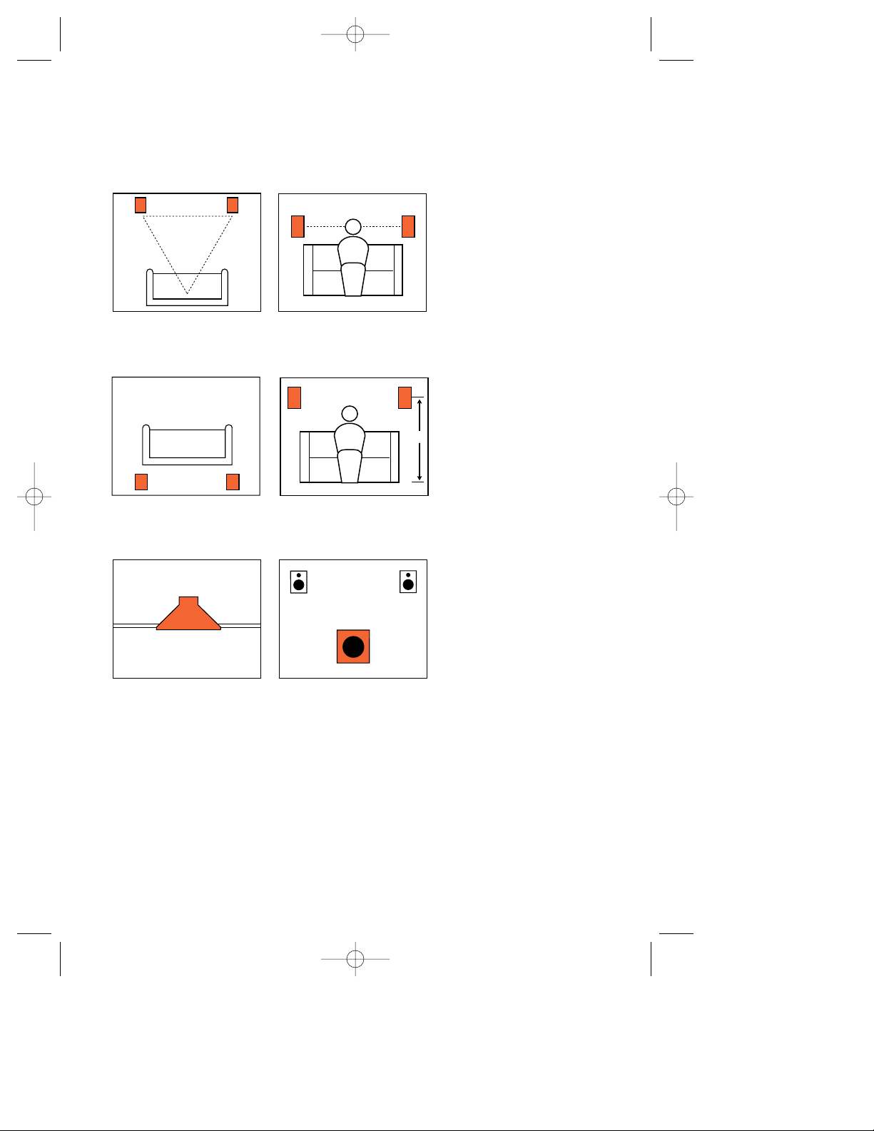
one. Speaker Placement
AS5, AS6, AS8 as front speakers
AS5, AS6, AS8 as rear speakers
AS65C in ceiling
AS SUB
5 – 6 ft.
AS Series Owner’s Manual 9/11/98 12:51 PM Page 2
Page 3
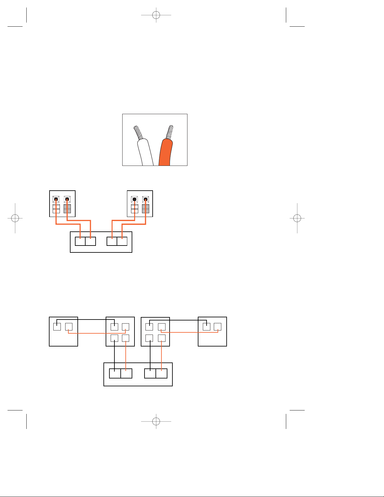
two. Speaker Connections
Speakers and electronics terminals have corresponding (+)
and (–) terminals. It is important to connect both speakers
identically: (+) on the speaker
to (+) on the amplifier and (–)
on the speaker to (–) on the
amplifier. Wiring “out of phase”
results in thin sound, weak bass
and a poor stereo image.
Connection Tips
AS5, AS6, AS8, AS65C
AS SUB
Wire Length Recommended Size
Up to 20 ft. 16 gauge
Up to 30 ft. 12 gauge
Greater than 30 ft. 10 gauge
– +– +
Front or Rear Speaker Outputs
LEFT RIGHT
LEFT
RIGHT
–
+
–
+
– +– +
– +– + – + – +
Receiver/Amplifier
LEFT RIGHT
Left
Right
– + – +
Right SatelliteLeft Satellite
Subwoofer
Output
Input
Output
Input
The wires for both speakers
should be the same length. If
one speaker is placed closer to
the amplifier than the other,
hide the excess wire behind
the wall.
The AS SUB has two pairs of
speaker connections. Connect
one set of terminals (input)
to the left channel of your
amplifier. Connect the other set
of terminals (input) to the right
channel of your amplifier. Then
connect the left satellite to the
left output and the right satellite to the right output.
Note: Diagram is for illustrative
purposes. For each channel it
does not matter which pair of
connectors is used for the input
or which pair is used for the
output.
AS Series Owner’s Manual 9/11/98 12:51 PM Page 3
Page 4
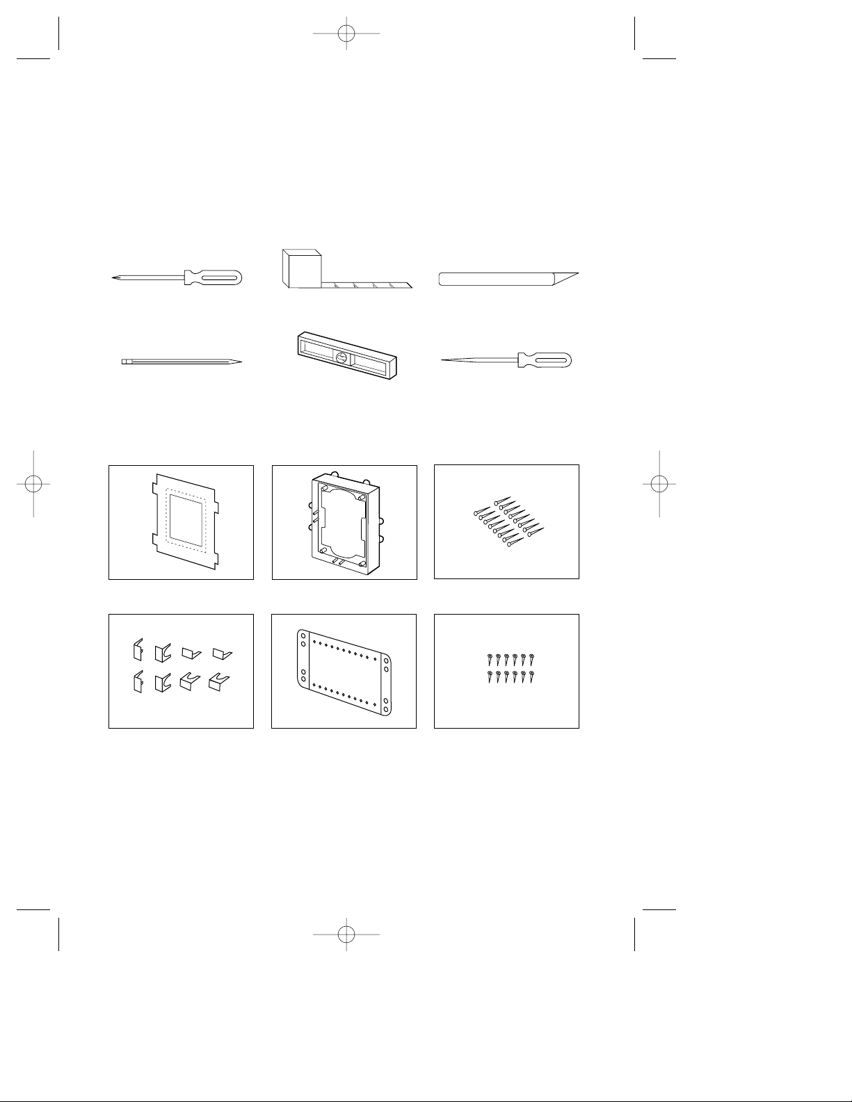
three. Installation
AS5, AS6, AS8
Phillips #2 screwdriver
Measuring tape
Utility knife
Pencil
Carpenter’s level
Awl
Installation Kit
Template
Speaker frame
Thread-forming screws
Retainer clips
Four mounting brackets
Tools Needed
The AS Series in-wall speakers
were
designed to be easily
installed. However, if you
are unsure of your ability to
properly install these loudspeakers, please contact your dealer
or a qualified installer.
Short phillips head screws
AS Series Owner’s Manual 9/11/98 12:51 PM Page 4
Page 5

Step One:
Remove the grille from the
speaker frame.
Step Two:
Determine the correct speaker
location.
Template
Tape
Level
Step Three:
Determine the speaker-frame
location.
≥1-1/2"
≥1-1/2"
≥1-1/2"
Step Four:
Cut the dry wall.
Step Five:
Place the mounting bracket on
the speaker frame using the
mounting guides (marked 3/8",
1/2", 5/8", and 3/4") corresponding to the thickness of
the dry wall.
Kerf Line
Step Six:
Place the frame assembly in
the wall.
Step Seven:
Connect the speaker wires to
the baffle assembly and install
baffle assembly in frame.
Do not overtighten the baffle
screws.
Step Eight:
Replace the metal grille.
Existing Construction
AS Series Owner’s Manual 9/11/98 12:51 PM Page 5
Page 6

New Construction
Step One:
Remove the grille from the
speaker frame.
Step Three:
Attach the proper mounting
brackets, marked and preset at
3/8", 1/2", 5/8", and 3/4", corresponding to the thickness of
the dry wall, to the speaker
frame.
Step Two:
Determine the correct speaker
location.
≥1-1/2"
≥1-1/2"
≥1-1/2"
Step Four:
Nail or screw the speaker-frame
assembly to the wall studs and
route the wires through the
frame opening.
Step Five:
Cut the drywall.
Step Six:
Connect the speaker wires to
the baffle assembly and install
baffle assembly in frame. Do
not overtighten the baffle
screws.
Step Seven:
Replace the metal grille.
After the Drywall is Installed
AS Series Owner’s Manual 9/11/98 12:51 PM Page 6
Page 7

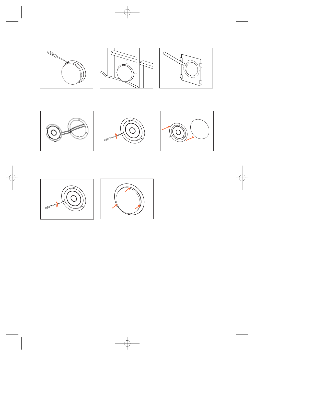
AS SUB
Step One:
Remove the grille from the
subwoofer frame.
Step Two:
Determine the correct
subwoofer location.
≥1-1/2"
≥1-1/2"
≥1-1/2"
Step Three:
Cut the drywall.
Step Four:
Loosen the eight phillips head
screws until the locking tabs
turn inward.
Step Five:
Connect the speaker wires to
the baffle assembly.
Step Six:
Place the subwoofer in the wall.
Step Seven:
Screw down each of the eight
phillips head screws. The tabs
will swivel into place and
secure the unit to the rear
surface of the drywall.
Step Eight:
Replace the metal grille.
AS Series Owner’s Manual 9/11/98 12:51 PM Page 7
Page 8
AS65C
Step One:
Remove the grille from the
speaker frame.
Step Two:
Determine the correct speaker
location.
≥1-1/2"
≥1-1/2"
≥1-1/2"
Step Three:
Cut the drywall.
Step Five:
Loosen the three phillips head
screws on the frame until the
locking tabs turn inward.
Step Four:
Connect the speaker wires to
the speaker.
Step Six:
Place the frame assembly in
the wall.
Step Seven:
Screw down each of the three
phillips head screws. The tabs
will swivel into place and
secure the unit to the rear
surface of the drywall.
Step Eight:
Replace the metal grille.
AS Series Owner’s Manual 9/11/98 12:51 PM Page 8
Page 9

Painting the Speaker Frame and Grille
AS Series loudspeakers can be
painted to match any style of
decor. If you wish to change
their color, the satin finish on
the grille and frame will function as a primer coat. Before
painting, install the paint guard
(in the assembly kit) securely
into the recess in the baffle.
This will protect the speaker
components and baffle from
paint residue.
Use a high-quality spray paint,
and apply a thin coat of color.
Be certain the grille perforations remain free of paint.
Filling them with paint will
diminish the sound quality.
Note: Gently remove the
acoustical foam blanket from
the grille before painting.
Reattach the blanket after the
paint has dried.
AS Series Owner’s Manual 9/11/98 12:51 PM Page 9
Page 10

If there is no sound from
either of the speakers, check
the following:
• Receiver/amplifier is on and a
source is playing.
• Check all wires and connections between receiver/amplifier
and speakers. Make sure all wires
are connected. Make sure none
of the speaker wires are frayed,
cut, or punctured.
• Review proper operation of
your receiver/amplifier.
If there is no sound coming
from one speaker, check the
following:
• Check the “Balance” control on
your receiver/amplifier.
• Check all wires and connections between receiver/amplifier
and speakers. Make sure all wires
are connected. Make sure none
of the speaker wires are frayed,
cut, or punctured.
If there is low bass output,
check the following:
• Make sure the connections to
the left and right “Speaker
Inputs” have the correct polarity
(+ and –).
If the system plays at low volumes but shuts off as volume is
increased, check the following:
• Check all wires and connections between receiver/amplifier
and speakers. Make sure all wires
are connected. Make sure none
of the speaker wires are frayed,
cut, or punctured.
• If more than one pair of main
speakers is being used, check the
minimum impedance requirements of your receiver/amplifier.
Troubleshooting
AS Series Owner’s Manual 9/11/98 12:51 PM Page 10
Page 11

Specifications
SYSTEM AS5 AS6 AS65C
Frequency Response (–6dB): 50Hz – 20kHz 40Hz – 20kHz 45Hz – 20kHz
Recommended Maximum
Amplifier Power*: 40 watts 50 watts 50 watts
Sensitivity: 88dB 90dB 90dB
Impedance: 8 ohms nominal 8 ohms nominal 8 ohms nominal
Crossover Frequency: 6kHz 5kHz 7kHz
Woofer: 5-1/4" 6-1/2" 6-1/2"
Tweeter: 1" titanium 1" titanium 1" titanium
Outside Dimensions (HxWxD**): 11 x 7-1/2 x 2-5/8" 13 x 7-1/2 x 2-3/4" 8-1/8 (dia.) x 2-3/4"
280 x 190 x 67mm 330 x 190 x 70mm 206 (dia.) x 70mm
SYSTEM AS8 AS SUB
Frequency Response (–6dB): 35Hz – 20kHz 32Hz – 300Hz
Recommended Maximum
Amplifier Power*: 60 watts 120 watts
Sensitivity: 88dB 88dB
Impedance: 8 ohms nominal 8 ohms nominal
Crossover Frequency: 5kHz 300Hz
Woofer: 8" 8"
Tweeter: 1" titanium N/A
Outside Dimensions (HxWxD**): 15-1/8 x 11 x 3-1/4" 11-13/16 x 11-13/16 x 3-1/4"
385 x 280 x 83mm 300 x 300 x 83mm
Occasional refinements may be
made to existing products without notice, but will always meet
or exceed original specifications
unless otherwise stated.
*The maximum recommended
amplifier power rating will
ensure proper system headroom
to allow for occasional peaks.
We do not recommend sustained
operation at these maximum
power levels.
** Mounting depth.
AS Series Owner’s Manual 9/11/98 12:51 PM Page 11
Page 12

JBL Consumer Products
80 Crossways Park West, Woodbury, NY 11797
8500 Balboa Boulevard, Northridge, CA 91329
1-800-336-4JBL (4525) (USA only)
www.jbl.com
©
1996 JBL, Incorporated. JBL is a registered trademark
of JBL, Incorporated.
Printed in USA 2/97 Part No. ASOM
A Harman International Company
AS Series Owner’s Manual 9/11/98 12:51 PM Page 12
Declaration of Conformity
We, JBL Europe A/S
Kongevejen 194B
DK-3460 Birkerød
DENMARK
declare in own responsibility, that the loudspeakers
described in this owner’s manual are in compliance
with technical standards:
EN 50 081-1/1992
EN 50 082-1/3.1995
Steen Michaelsen
JBL Europe A/S
Birkerød. DENMARK. 7/96
 Loading...