

Page 1
Instruction Manual
A. Introduction:
Although the company's roots extend back
to the early days of motion picture sound, it
has only been in the last few years that JBL
has made a significant impact on the commercial
theater market. Some of the reasons for this are
the company's preeminence in high-quality sound
reinforcement in general and the development of
the notion of flat power response in particular.
In just the last year, JBL theater systems have
been incorporated into some of the most presti-
geous dubbing theaters and screening rooms in
the film industry. We now feel that the time is
right to prepare a comprehensive applications
manual for our theater dealers to aid them in
system design and specification and to give them
an edge over their competitors.
B. Systems for Smaller Houses:
1.
A summary of house types:
By far, most of the theaters being built
today are long rectangular rooms. They are
usually built in groups called multiplex
theaters for reasons of economy. Most of
these theaters are mono, with a single
loudspeaker behind the screen, and the
seating capacity usually ranges from 200
to 500. In general, the larger houses, those
seating 1000 or more, were built some years
ago,
and these are usually equipped with
three or five loudspeakers behind the screen
and will have a multi-speaker surround
channel located on the rear and side walls.
A very few houses, usually found only in
larger cities, will have special effects
low-frequency channels, such as Sensurround,
for special screenings of important films.
Motion Picture
Loudspeaker Systems
2.
General Acoustical Characteristics:
Historically, motion picture theaters,
whatever their size, have been acoustically
"dead"
rooms; that is, they have consider-
able absorption on the boundaries, and rever-
beration times, even in the larger houses,
rarely exceed 1.25 seconds. More likely, we
will find the reverberation times in smaller
houses to be in the 0.5 second range. The
reason for this of course has to do with
arti-
culation and clarity of dialog.
The most common method of treating the
interior of theaters is with velour draping.
This is an interior treatment only; structurally,
the architect relies on solid block walls to
minimize sound leakage from adjacent theaters.
One of the most common problems encoun-
tered in theaters is a slap or reflection off
the back
wall,
which often goes untreated.
Should the back wall be curved, then the
effect may be even worse, due to focussing of
the reflection back to the front.
3. Sound Level Requirements:
Average peak levels of 85 dB-SPL are common
in the theater. A minimum headroom figure
above this would be 10 dB, but JBL recommends
15 dB for a greater measure of safety. The
following factors are taken into consideration
in determining the kind of system to specify
and the amount of amplifier power which will
be required:
a.
Room volume
b. Room boundary area
c. Reverberation time
d.
System sensitivity and power
rating
e. System directivity index
Page 2
Table I presents JBL's system recommenda-
tions based on general assumptions regarding
room ratios and reverberation times. All the
theater dealer or contractor has to do is
calculate the room volume and go to that entry
in the table. The mid-house levels are those
calculated by assuming that the reverberant
sound in the theater and the direct sound from
the loudspeakers are equal. Beyond that point,
the sound level will drop off somewhat, while
in front of that point the sound will be louder.
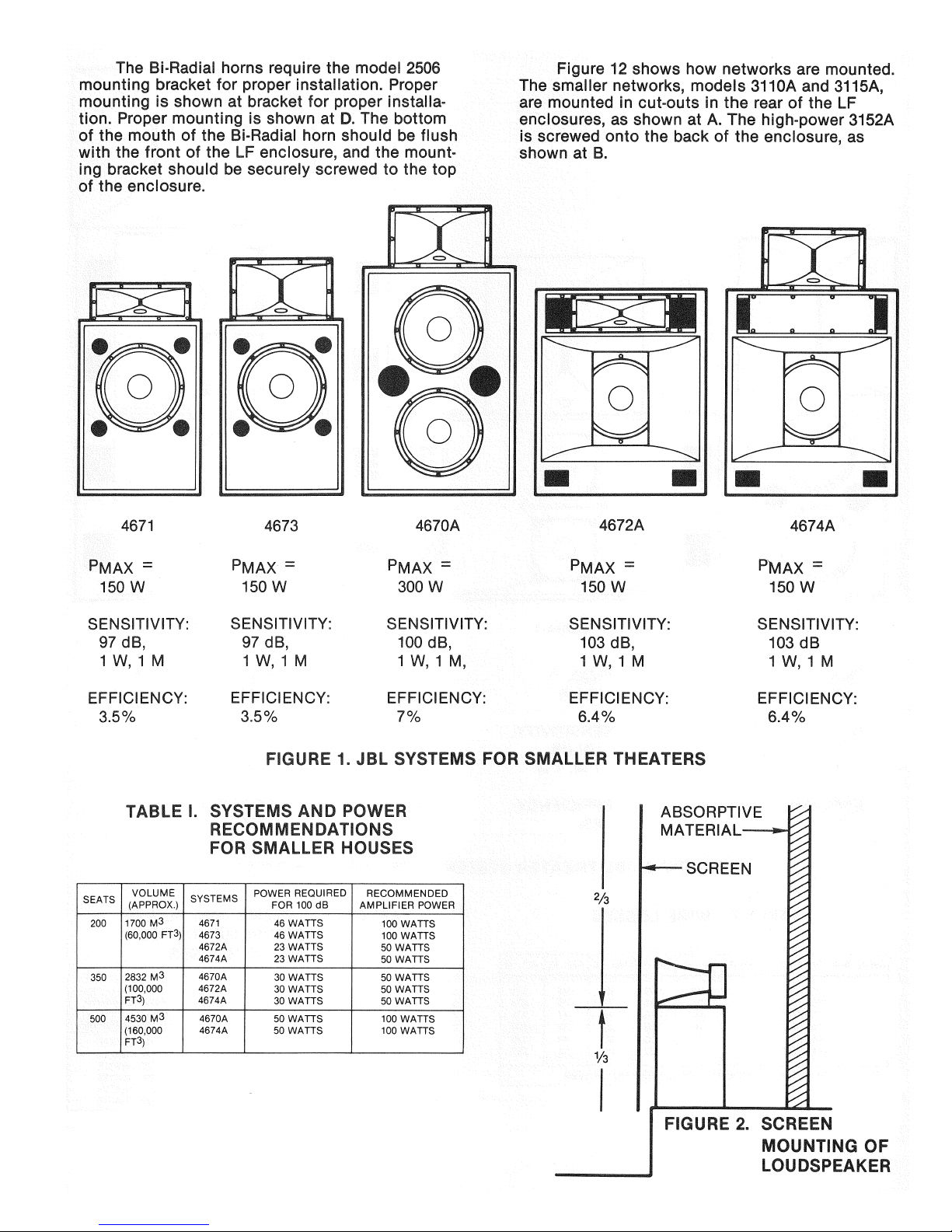
Details of the various JBL systems recom-
mended for single channel use in multiplex
theaters are given in Figure 1. The choice
between several systems, all of which might
meet the specification, must be based on a num-
ber of considerations. In general, the models
4672A and 4674A will result in less amplifier
power requirement; however, these systems begin
to roll off below 120 Hz, while the models 4671
and 4673 extend smoothly down to 45 Hz. Another
consideration is enclosure depth. The space be-
hind some screens can be as small as 0.6 meter
(2 feet), and this often dictates system choice.
4.
System Installation:
Whenever possible, the screen loudspeaker
should be located one-third the way up the screen.
Should the screen itself be higher than usual,
requiring patrons seated toward the front of the
house to look upward, then the loudspeaker may
be placed somewhat lower. As a rule, the
loud-
speaker high-frequency element should be aimed
toward the farthest seats. This is certainly the
way to go if the back wall is draped. If it
cannot be draped, then tilting the system down
a bit may help. The system should be placed as
close as 0.3 meter
(1
foot) to the screen to
minimize the effect of high-frequency sound
reflecting between the screen and the wall be-
hind the loudspeaker. If possible, the wall area
behind the screen should be treated with sound
absorptive material. See Figure 2 for details of
this.
Most of the wire runs in a theater will be
short enough so that a wire gauge no greater
than AWG #12 will be required. All JBL theater
systems should be considered as 8-ohm systems
in making line loss calculations, and the general
rule is that line losses should be held to no
greater than 0.5 dB. Table II shows line losses
for various runs and gauges.
The theater dealer should always try to speci-
fy a stereo amplifier which can be bridged for
mono operation. Care must be taken that the
amplifier's bridged mono rating into 8 ohms will
not be exceeded.
C. Systems for Larger Houses:
1.
Choosing the system:
Figure 3 shows the JBL systems normally
specified for multi-channel use in theaters.
Note that these systems all make use of Bi-Radial
high-frequency horns. The models 4675 and
4676A-1 make use of the 2360 90-by-40 degree
horn for normal coverage, while the 4676A-2
uses a pair of 2365 60-by-40 horns splayed for
90-degree coverage.
Of these three systems, the 4675 will be the
most useful because it exhibits the smoothest
power response of any system that JBL makes.
This is, in fact, the one that has become well
known in film production circles as "JBL's new
theater system."
Table III will enable the theater dealer to
specify and choose power for these systems in
larger theaters. The powers given for each
loud-
speaker enable each channel to reach a level of
100 dB in the house. Depending on the exact na-
ture of the multi-channel installation, the
behind-the-screen resources may be five
full-
range channels, or three full-range channels and
two low-frequency augmentation channels.
2.
Powering the system:
With these larger systems, we have the option
of biamplification. While this is more expensive
than the normal single amplifier approach, it does
result in far cleaner sound on peaks by making it
impossible for low-frequency signals to modulate
high-frequency signals. Figure 4 shows the two
ways that these larger systems can be imple-
mented electrically.
Biamplification allows considerably more
power to be delivered to the LF portions of theater
systems, since the passive dividing network is
being bypassed. Biamplification should certainly
be considered essential if the theater installation
is intended for playback at levels in excess of
100 dB.
3. Installation of the system:
As we stated earlier, it is customary for
screen loudspeakers to be located about
one-third the way up the screen and as close
as 0.3 meter
(1
foot). The center loudspeaker
should be normal to the screen, but the flank-
ing loudspeakers may be toed in slightly, as
shown in Figure 5, in order to ensure even
coverage, and consequently better stereo, for
those patrons seated off to one side.
Page 3
D. Surround Channels:
1= Genera! requirements:
While there is little consistent practice in
specifying and implementing surround channels,
we can lay down the following requirements:
a.
The total acoustical power delivered
by the ensemble of surround
loud-
speakers should be equal to one of
the screen channels. There are pro-
bably not many surround channels
which meet this requirement, but
it is essential if the full impact
of surround information is to be
appreciated. While a 15-dB headroom
factor is a part of the power calcu-
lations for the screen channels, it
may be unreasonable to demand that
of the surround channel. Thus, a
requirement that the surround channel
be able to produce a level in the
house of 95 dB-SPL will suffice. In
the case of the distributed 200 mm
(8") speaker system, a level of
92 dB is deemed sufficient.
b. The quantity of surround loudspeakers
should be sufficient so that listeners
are not aware of only one of them.
This usually means a minimum of
eight: three each on the side walls
and two on the back
wall.
c. The surround loudspeakers should
exhibit wide dispersion so that the
entire audience area can appreciate
even coverage across the frequency
range.
d.
Surround loudspeakers should be
unobtrusive and not interfere with
theater decor. This requirement may
run counter to some of the acoustical
requirements in that size is related
to system efficiency.
The JBL 4401 monitor loudspeaker works
extremely well since a small number of them,
usually less tham 12, will provide the desired
level in many houses. The MC 4401 mounting
cradle provides a convenient method of
wall-
mounting and angling the 4401 system. Table IV
presents details of surround loudspeaker
selection.
The use of multiple 200 mm (8") loudspeakers
has been favored by Dolby Laboratories. While the
hardware costs may be reasonable, the labor costs
for this approach are accordingly higher. For this
type of system, the JBL 8140 co-motional trans-
ducer will be a logical choice. The baffles used
in such an installation should ideally be
con-
structed according to the transducer manufac-
turer's plans or recommendations so that low-
frequency response will be adequate. A lower cost
approach calls for using one of the many standard
tilted front enclosures. As a rule, these are too
small in volume for proper low-frequency response,
and the client should understand this at the outset.
The 4671 theater system is recommended for
high-power surround use. With an efficiency of
3.5%, relatively few of these units are required.
They would normally be specified when the entire
theater reproduction system was called upon to
produce levels in the 105-to-110-dB range.
2.
Powering the surround channel:
Figure 6 presents details of the implementa-
tion of the surround channel. At C through E, we
show details of the electrical distribution. Depen-
ding on the number of surround loudspeakers, the
hook-up will be series-parallel, and the resulting
impedance can usually be held to no less than 4
ohms.
An amplifier should be chosen whose 4-ohm
power rating will not be exceeded. In some cases,
the JBL model 9375 line matching autotransformer
will be useful in maintaining the desired im-
pedance. For the 200 mm (8") loudspeakers, a
70-volt distribution system should be used. See
JBL Technical Note, Volume 1, Number 2, for
details of this method.
E. Subwoofer Systems:
1.
Background:
Universal's introduction of "Sensurround"
during the seventies brought special effects very-
low-frequency channels into the motion picture
theater. Typically, these channels cover the range
from 20-25 Hz up to 40-50 Hz. Quite high acoustical
power output is required, since the ear is relatively
insensitive to extremely low frequencies.
2.
Implementation:
Most installations of subwoofers are dictated
by the requirements of particular screenings, and
instructions will generally come from the studios
or through the film distributors. The Dolby model
CP200 processor provides a low-frequency output
that may be used to drive a subwoofer channel
directly.
Table V presents data on selecting the
number of subwoofer modules needed for parti-
cular sound levels in theaters of different
volumes. The enclosure recommended here is the
4518.
Its specifications with the 2245H LF driver
are detailed in column 4 of JBL Technical Note,
Volume 1, Number 1. It is important to provide
adequate and stable power for proper subwoofer
operation.
Whenever possible, the amplifiers
should be located at the loudspeakers themselves.
Note that as the number of modules is
doubled,
the sound pressure increases 6 dB.
Three dB are due to the doubling of power
Page 4
handling,
and the remaining three come from
mutual coupling, the tendency of two loudspeakers
to behave as a single, more efficient loudspeaker.
F. Acoustical Response:
1.
Concept of flat power response:
to ship the components complete so that the
systems can be readily assembled. It is a wise
dealer, however, who will keep a good stock of
replacement components and mounting hardware.
The systems do not travel well in their assem-
bled form, so they should always be assembled at
their final site. All transducers should be checked
prior to being sent out, however.
While most loudspeaker systems are fairly
flat on axis, they tend to narrow considerably in
their coverage angles at high frequencies. Their
power response is said to roll off. If a
loud-
speaker maintains fairly constant horizontal and
vertical coverage angles over most of its fre-
quency range, then flat on-axis response will also
imply flat power response. Since about half of the
sound heard in the theater has been reflected at
least once, it is important that loudspeakers
exhibit fairly flat power response if the reproduced
sound is to be natural.
Another consequence of using loudspeakers
with flat power response is that little system equal-
ization is required. Figure 7 illustrates this. At
A, we see the boundary absorption in a typical
well-designed theater. Note that it is quite flat
over the frequency range. High-frequency losses
due to air absorption are shown at B, and typical
high-frequency screen losses are shown at C.
When we add up all of these, we get the response
shown at D, and this is exactly the acoustical
response we would observe in the room if we
were using a loudspeaker that had flat power
response.
Figure 8 shows the standard "house curve"
to which most theater systems are equalized.
Note that it closely resembles the summed
curve shown in Figure 7,D, indicating that flat
power response systems will require little, if any
added equalization in most houses.
JBL's theater systems using Bi-Radial horns
exhibit essentially flat power response as well
as flat on-axis response. The smaller systems
exhibit flat on-axis response, but their power
response rolls off slightly at high frequencies.
JBL's passive dividing networks provide for a
high-frequency boost which effectively makes any
of the systems power-flat at high frequencies.
In the smaller systems, this may be accompanied
by a slight on-axis rise at high frequencies.
Nevertheless, we recommend that the high-
frequency boost be used in all theater applica-
tions.
H. System Assembly:
2.
Details of assembly:
We present in Figure 9 detailed wiring
dia-
grams of each of the theater systems, along with
a complete listing of components in each system.
Figure 10 shows details of mounting LF trans-
ducers in the various 4500-series LF enclosures.
The models 4507, 4508 and 4518 all require front-
mounting of transducers. There are T-nuts
mounted on the back side of the baffle, and the
four mounting screws for each transducer engage
these as shown at A.
Both the 4550BKA and 4560BKA have
demountable back panels. These are removed and
the LF transducers mounted in place with screws
engaging T-nuts, as shown at B.
High-frequency horns are mounted as shown
in Figure 11. The 2370 horn-2425 HF driver com-
bination is placed directly on top of the 4507 LF
enclosure, and its mouth is parallel with the front
of the LF enclosure. It should be mounted flush
with the front of the LF enclosure. Two angle irons
may be used to secure the front of the horn to the
enclosure, as shown at A. An alternate way to
mount the smaller Bi-Radial horns (2370 and 2380)
is to screw the bottom front flange into the upper
front edge of the LF enclosure, as shown in Figure
11C.
The user should note in general that Bi-Radial
horns,
because of their extended vertical coverage
at high frequencies, do not normally have to be
tilted with respect to the LF enclosure in order to
provide proper coverage of the audience area.
When the 4560BKA enclosure is used, the
2370 horn is mounted in a space provided at the
top of the LF enclosure. The upper panel is
removed,
and the horn is screwed into place, as
shown at B.
The 2380 horn is mounted on top of the LF
enclosure in the 4670A, 4673, and 4674A systems.
With the 2445 HF driver in place, the horn-driver
combination sits on top of the enclosure with its
mouth parallel to the front of the enclosure. As
in the case shown at A, the front of the horn
should be secured to the enclosure top with angle
irons,
or by screwing into the front edge of the LF
enclosure.
1.
General comments:
JBL's theater systems are shipped to the
dealer in component form. Every attempt is made
Page 5
The Bi-Radial horns require the model 2506
mounting bracket for proper installation. Proper
mounting is shown at bracket for proper installa-
tion.
Proper mounting is shown at D. The bottom
of the mouth of the Bi-Radial horn should be flush
with the front of the LF enclosure, and the mount-
ing bracket should be securely screwed to the top
of the enclosure.
Figure 12 shows how networks are mounted.
The smaller networks, models
311 OA
and 3115A,
are mounted in cut-outs in the rear of the LF
enclosures, as shown at A. The high-power 3152A
is screwed onto the back of the enclosure, as
shown at B.
4671 4673
4670A
4672A
4674A
PMAX =
150 W
PMAX =
150 W
PMAX =
300 W
PMAX =
150 W
PMAX =
150 W
SENSITIVITY:
97 dB,
1 W, 1 M
SENSITIVITY:
97 dB,
1 W, 1 M
SENSITIVITY:
100 dB,
1 W, 1 M,
SENSITIVITY:
103 dB,
1 W, 1 M
SENSITIVITY:
103 dB
1 W, 1 M
EFFICIENCY:
3.5%
EFFICIENCY:
3.5%
EFFICIENCY:
7%
EFFICIENCY:
6.4%
EFFICIENCY:
6.4%
FIGURE 1. JBL SYSTEMS FOR SMALLER THEATERS
TABLE I. SYSTEMS AND POWER
RECOMMENDATIONS
FOR SMALLER HOUSES
SEATS
VOLUME
(APPROX.)
SYSTEMS
POWER REQUIRED
FOR 100 dB
RECOMMENDED
AMPLIFIER POWER
200
1700 M3
(60,000 FT3)
4671
4673
4672A
4674A
46 WATTS
46 WATTS
23 WATTS
23 WATTS
100 WATTS
100 WATTS
50 WATTS
50 WATTS
350
2832 M3
(100,000
FT3)
4670A
4672A
4674A
30 WATTS
30 WATTS
30 WATTS
50 WATTS
50 WATTS
50 WATTS
500
4530 M3
(160,000
FT3)
4670A
4674A
50 WATTS
50 WATTS
100 WATTS
100 WATTS
ABSORPTIVE
MATERIAL
2/3
V3
SCREEN
FIGURE 2. SCREEN
MOUNTING OF
LOUDSPEAKER
Page 6

4675
4G76A-, 4676A-2
PMAX =
300 W
PMAX =
300 W
PMAX =
300 W
SENSITIVITY:
100 dB,
1 W, 1 M
SENSITIVITY:
106 dB,
1 W, 1 M
SENSITIVITY:
109 dB,
1 W, 1 M
EFFICIENCY:
7%
EFFICIENCY:
8%
EFFICIENCY:
16%
FIGURE 3. JBL THEATER SYSTEMS FOR LARGER HOUSES
TABLE II. WIRE LOSSES
WIRE RUN (DOUBLE; COPPER)
NO.
10
NO .12
NO .14
NO .16
NO.
18
10M (33')
.02
.032
.05
.08 .125
20 M (66')
.04 .064
.10
.16 .250
30M (100')
.06 .096
.15
.24
.375
40M (132')
.08 .128
.20
.32 .500
50M (165')
.1 .160
.25
.40
.625
60M (200')
.12 .192
.30
.48
.750
FOR 8H LOAD, LINE RESISTANCE SHOULD BE
0.552
OR LESS.
TABLE III. SYSTEMS AND POWER
REQUIREMENTS FOR
LARGER HOUSES
SEATS
VOLUME
(APPROX.)
SYSTEMS
POWER REQUIRED
FOR 100 dB
RECOMMENDED
AMPLIFIER POWER
PER LOUDSPEAKER
500-
8500 M
3
4675
72 WATTS
150 WATTS
1000
(300,000 FT3)
4676A-1
63 WATTS
125 WATTS
14,160 M
3
M676A-2
42 WATTS
100 WATTS
1000-
14,160 M
3
4675 90 WATTS
200 WATTS
2000
(500,000 FT3)
4676A-1
79 WATTS
200 WATTS
M676A-2 53 WATTS
125 WATTS
BECAUSE OF THEIR EXTREMELY HIGH POWER RATINGS,
THESE SYSTEMS WOULD BE SPECIFIED WITH MUCH LARGER
POWER AMPLIFIERS THAN SUGGESTED HERE FOR USE IN
SPECIAL, HIGH SOUND LEVEL APPLICATIONS.
Page 7

AMPLIFIER
HF
NETWORK
HF AMPLIFIER
LF OUT
LF
k
FULL-RANGE AMPLIFICATION
BIAMPLIFICATION
*500 Hz, POWER RESPONSE
CORRECTED CARD TO BE USED
FIGURE 4. FULL-RANGE AMPLIFICATION AND BIAMPLIFICATION
TABLE IV. SURROUND SYSTEM DATA
SEATS
4401 MONITOR
8140 DISTRIBUTED
SYSTEM
4671
500-
8 UNITS
30 UNITS @
6 UNITS @
1000
@ 50 WATTS
5 WATTS 100 WATTS
EACH
EACH* EACH**
1000-
12 UNITS @
38 UNITS @
10 UNITS®
2000
50 WATTS
5 WATTS 100 WATTS
EACH
EACH*
EACH**
*FOR A MAXIMUM LEVEL OF 92 dB
'*FOR A MAXIMUM LEVEL OF 107 dB
BOTH 4401 AND 8140 SURROUND SYSTEMS SHOULD
BE HIGH-PASSED AT 40 Hz OR HIGHER.
TABLE V. SUBWOOFER SELECTION DATA
NUMBER OF MODULES
EFFICIENCY
ELECTRICAL
POWER INPUT
ACOUSTIC
POWER
SOUND LEVELS
500-
1000-
1000 SEATS 2000 SEATS
1
2%
300 WATTS
6 WATTS 101 dB
100 dB
2
4%
600 WATTS
24 WATTS
107 dB
106 dB
4
8%
1200 WATTS
96 WATTS 113 dB
112 dB
8
16%
2400 WATTS
384 WATTS
119 dB
118 dB
Page 8

/
/ \ / \ \
FIGURE 5. POSITIONING LOUDSPEAKERS BEHIND THE SCREEN
2/3
•
• • •
T
1/3
i
r
1
— .
A. SIDE VIEW
~•
L_J CT™
]
]
mi—II—i
B. TOP VIEW
FIGURE 6. SURROUND SYSTEM IMPLEMENTATION
Page 9

FIGURE 6, CONT'D. ELECTRICAL CONSIDERATIONS
70-VOLT OUTPUT
OF AMPLIFIER
(MAKE SURE AMPLIFIER
HAS ADEQUATE
POWER OUTPUT)
200 MM (8") LOUDSPEAKERS USED IN MULTIPLE,
70-VOLT CONFIGURATION
JBL 9315HT
*EACH LOUDSPEAKER
TAPPED AT 5 WATTS
FIGURE 6, CONT'D. ELECTRICAL CONSIDERATIONS
8 UNITS =
12 UNITS =
4X2
LEFT
SIDE
RIGHT
SIDE
5.30
LEFT
SIDE
RIGHT
SIDE
Page 10

ROOM BOUNDARY LOSSES
EXPRESSED IN dB
(TYPICAL)
AIR LOSSES AT 15 METERS,
50%
RELATIVE HUMIDITY
SCREEN LOSSES
(15 MIL THICK VINYL, 8% OPENING)
FIGURE 7, RESPONSE IN THE HOUSE
FIGURE 8. ISO STANDARD PLAYBACK RESPONSE
dB,
RELATIVE
LEVEL
dB,
RELATIVE
LEVEL
dB,
RELATIVE
LEVEL
SUM OF CURVES
A, B, AND C
dB,
RELATIVE
LEVEL
DATA FROM
FIGURE 7
Page 11

A. 4671: Components:
B. 4673: Components:
C.
4670A: Components:
D. 4672A: Components:
E. 4674A: Components:
F. 4675: Components:
G.
4676A-1:
Components:
H. 4676A-2: Components:
1-4507
Low Frequency Enclosure
1-2225H
Low Frequency Transducer
1-2370
High Frequency Horn
1-2425J
High Frequency Driver
1-311
OA Network
1-4507
Low Frequency Enclosure
1-2225H
Low Frequency Transducer
1-2380
High Frequency Horn
1-2445J
High Frequency Driver
1-3115A
Network
1-4508
Low Frequency Enclosure
2-2225J Low Frequency Transducers
1-2380
High Frequency Horn
1-2445J
High Frequency Driver
1-3152A
Network
1-4560BKA Low Frequency Enclosure
1-2225H
Low Frequency Transducer
1-2370
High Frequency Horn
1-2425J
High Frequency Driver
1-311
OA Network
1-4560BKA Low Frequency Enclosure
1-2225H
Low Frequency Transducer
1-2380
High Frequency Horn
1-2445J
High Frequency Driver
1-3115A
Network
1-4508
Low Frequency Enclosure
2-2225J Low Frequency Transducers
1-2360
High Frequency Horn
1-2445J
High Frequency Transducer
1-2506
Mounting Bracket
1-3152A
Network
1-4550BKA Low Frequency Enclosure
2-2225J Low Frequency Transducers
1-2360
High Frequency Horn
1-2445J
High Frequency Transducer
1-2506
Mounting Bracket
1-3152A
Network
2-4550BKA Low Frequency Enclosures
4-2225H Low Frequency Transducers
2-2365 High Frequency Horns
2-2445J High Frequency Drivers
2-2506 Mounting Brackets
1-3152A
Network
FIGURE 9. JBL THEATER SYSTEMS COMPONENTS AND WIRING DIAGRAMS
Page 12

J.
Wiring Diagram for:
4671
4672A
4673
4674
K. Wiring Diagram for:
4670A
4675A
4676A-1
FIGURE 9, CONT'D.
•
2225H
Page 13

L. Wiring Diagram for:
4676A-2
Note:
Splay each HF Horn 22 1/2° off center
(Total Splay angle of 45°)
FIGURE 9, CONT'D.
FIGURE 10. LF ENCLOSURE ASSEMBLY INSTRUCTIONS
3152A
A. MOUNTING LF TRANSCLUCERS IN 4507, 4508,
AND 4518
B. MOUNTING LF TRANSDUCERS IN 4550BKA
AND 4560BKA
Page 14

HORN/DRIVER
SCREWED IN PLACE
BI-RADIAL HORN
4 WOOD SCREWS
INTO FRONT EDGE
OF LF ENCLOSURE
LFENCLOSURE
FIGURE 11. MOUNTING HORNS IN THEATER SYSTEMS
ANGLE IRON'
PANEL REMOVED
2506 ADAPTER
HF DRIVER
Page 15

FIGURE 12. MOUNTING NETWORKS
INCLUDED
WITH
NETWORK
INSERT
T-NUTS
#6
SCREWS
TERMINAL BOARD
PLATE REMOVED
FROM INSIDE
Page 16

JBL Incorporated
RO.
Box
2200
8500 Balboa Boulevard
Northridge, California 91329
U.S.A.
 Loading...