


Instruction Manual
Motion Picture Loudspeaker Systems:
A Guide To Proper Selection And installation
A. Introduction:
B. Systems for Smaller Houses:
In recent years, JBL has emerged as the predomi-
nant manufacturer of loudspeaker systems for the mo-
tion picture theater. Our products are to be found in the
most prestigious screening rooms and dubbing theaters
in Hollywood, including Warner Hollywood Studios, Glen
Glenn Sound, The Burbank Studios, Universal Studios,
and Todd-AO. The recent installation of a JBL system in
the Goldwyn Theater of the Academy of Motion Picture
Arts and Sciences represents a benchmark for our com-
pany. Our components have also been selected by
Lucasfilm, Ltd., for their THX theater system.
There are several reasons for JBL's success in mo-
tion picture sound. Foremost here is our concept of flat
power response, which results in an order of improve-
ment in sound coverage in the theater. Second, our
components are of proven reliability and have extended,
inherently smooth response. In addition, we manufac-
ture components for all aspects of theater sound. JBL's
systems are very cost effective when compared to the
vented horn/multicell designs of earlier years.
This manual is intended for both theater dealers and
prospective purchasers of theater systems. It will be use-
ful as a guide to the selection and installation of systems,
and it will provide considerable theoretical background
for the specifying engineer.
1.
A Summary of House Types:
By far, most of the theaters constructed today are
relatively small rectangular rooms. They are usually built
in groups known as multiplex theaters for economic rea-
sons.
Most of these theaters are monophonic, with a
sin-
gle loudspeaker behind the screen, and seating capacity
ranges from 200 up to 500.
2.
General Acoustical Characteristics:
Motion picture theaters are generally acoustically
"dead"
rooms, with reverberation time, even in the
larg-
est houses, not exceeding 1.25 seconds. In most multi-
plex theaters, reverberation times are on the order of 0.5
seconds. The short reverberation time ensures clear dia-
log throughout the house.
The most common interior treatment of theaters is
double-fold velour, which may be placed on the side and
rear walls. This will provide freedom from unwanted re-
flections, but it does nothing to isolate one multiplex
space from the adjacent one. Here, the architect must
rely on solid block walls for good isolation.
Any unusual acoustical problems should be referred
to a qualified acoustical consultant.
3. Sound Level Requirements:
Normal peak levels of 85 dB SPL are common in the
theater. A minimum headroom level above this figure
would be 10 dB; that is, the system should be capable of
handling peaks up to 95 dB-SPL Wherever possible,
JBL recommends that a headroom figure of 15 dB be
designed into the system.
The following factors have been taken into account
in determining system and amplifier choice for various
house sizes:
a. Room volume
b. Room boundary
c. Reverberation time
d.
System sensitivity and power rating
e. System directivity index
4.
Recommendations for Various Size Theaters:
A. For theaters seating up to 200 patrons; volume
approximately 1700 cubic meters (60,000 cubic feet):
*Preferred system: Model 4673 (direct radiator LF)
Power needed for 100 dB: 46 watts
Recommended power amplifier: JBL 6230 in
bridged mode (300 watts into 8 ohms)
Characteristics: Broad-band sensitivity 97 dB, one
watt at one meter; 500-Hz crossover into Bi-Radial horn;
integral power response correction; smooth response
down to 45 Hz; ideal quality for both dialog and music;
shallow profile.
* Alternate system: Model 4671 (direct radiator LF)
B. For theaters seating up to 350 patrons: volume
approximately 2800 cubic meters (100,000 cubic feet):
*Preferred system: Model 4670B
Power needed for 100 dB: 30 watts
Recommended power amplifier: Single section of
JBL 6230 (75 watts into 4 ohms, the impedance of the
low-frequency section of the 4670B system.)
Characteristics: Sensitivity, 100 dB, one watt at one
meter; 500-Hz crossover for most natural dialog and
music quality; integral power response correction; LF
response smooth down to 45 Hz; shallow profile
'Alternate vented horn systems: Models 4672A and
4674A
Power needed for 100 dB: 30 watts
Characteristics: Mid-band sensitivity, 103 dB, one
watt at one meter; LF response limited due to horn
load-
ing;
to be specified where available amplifier power is
limited (typically, 50 watts or less)
C. For theaters seating up to 500 patrons: volume
approximately 4500 cubic meters (160,000 cubic feet):
'Preferred system: Model 4670B
Power needed for 100 dB: 50 watts
Recommended power amplifier: single section of
JBL 6260 (300 watts can be delivered into 4 ohms, the
impedance of the low-frequency section of the 4670B
system)
Characteristics: Sensitivity, 100 dB, one watt at one
meter; 500-Hz crossover for most natural dialog and
music quality; integral power response correction;
smooth response down to 45 Hz; shallow profile
Power needed for 100 dB: 46 watts
Recommended power amplifier: JBL 6230 in
bridged mode (300 watts into 8 ohms)
Characteristics: Broad-band sensitivity, 97 dB, one
watt at one meter; 800-Hz crossover with integral power
response correction; smooth response down to 45 Hz;
slightly less realistic on dialog than recommended sys-
tem;
shallow profile
'Alternate vented horn system: Model 4674A
Power needed for 100 dB: 50 watts
Characteristics: Mid-band sensitivity, 103 dB, one
watt at one meter; LF response limited due to horn
load-
ing;
should be specified only where available amplifier
power is limited (100 watts or less)
* Alternate vented horn systems:
Models 4672A and 4674A
Power needed for 100 dB: 23 watts
Characteristics: Mid-band sensitivity, 103 dB, one
watt at one meter; LF response limited due to horn
load-
ing;
to be specified where available amplifier power is
limited (typically, 50 watts or less)
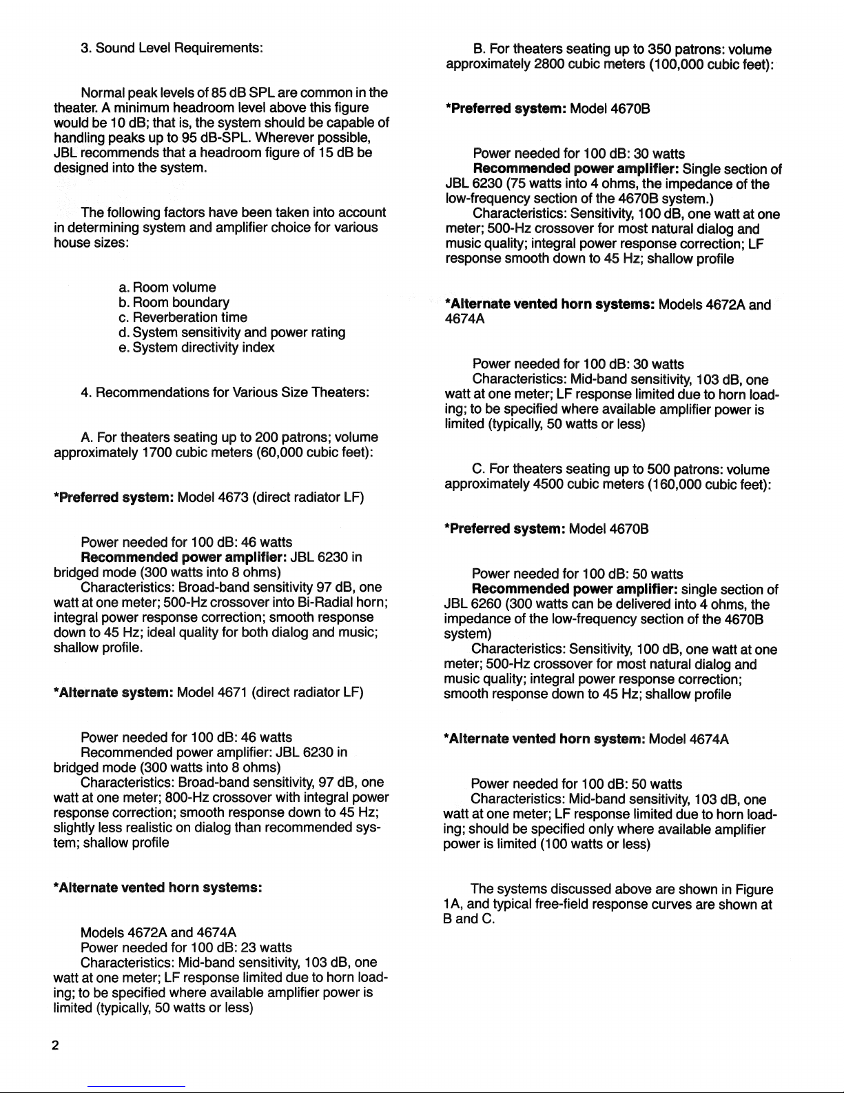
The systems discussed above are shown in Figure
1
A, and typical free-field response curves are shown at
B and C.
2

FIGURE 1. SYSTEMS FOR SMALLER HOUSES
FIGURE 1A. LINE DRAWINGS
4671
PMAX =
150 W
SENSITIVITY:
97 dB,
1 W, 1 M
4673
PMAX =
150 W
SENSITIVITY:
97 dB,
1 W, 1 M
4670B
PMAX =
300 W
SENSITIVITY:
100 dB,
1 W, 1 M,
4672A
PMAX =
150 W
SENSITIVITY:
103 dB,
1 W, 1 M
4674A
PlVlAX =
150 W
SENSITIVITY:
103 dB
1 W, 1 M
FIGURE 1B. ON-AXIS RESPONSE OF 4670B
(2TT
LOADING);
HIGH-FREQUENCY POWER RESPONSE
CORRECTED.
3
dB
Relative
Response
Frequency in Hz
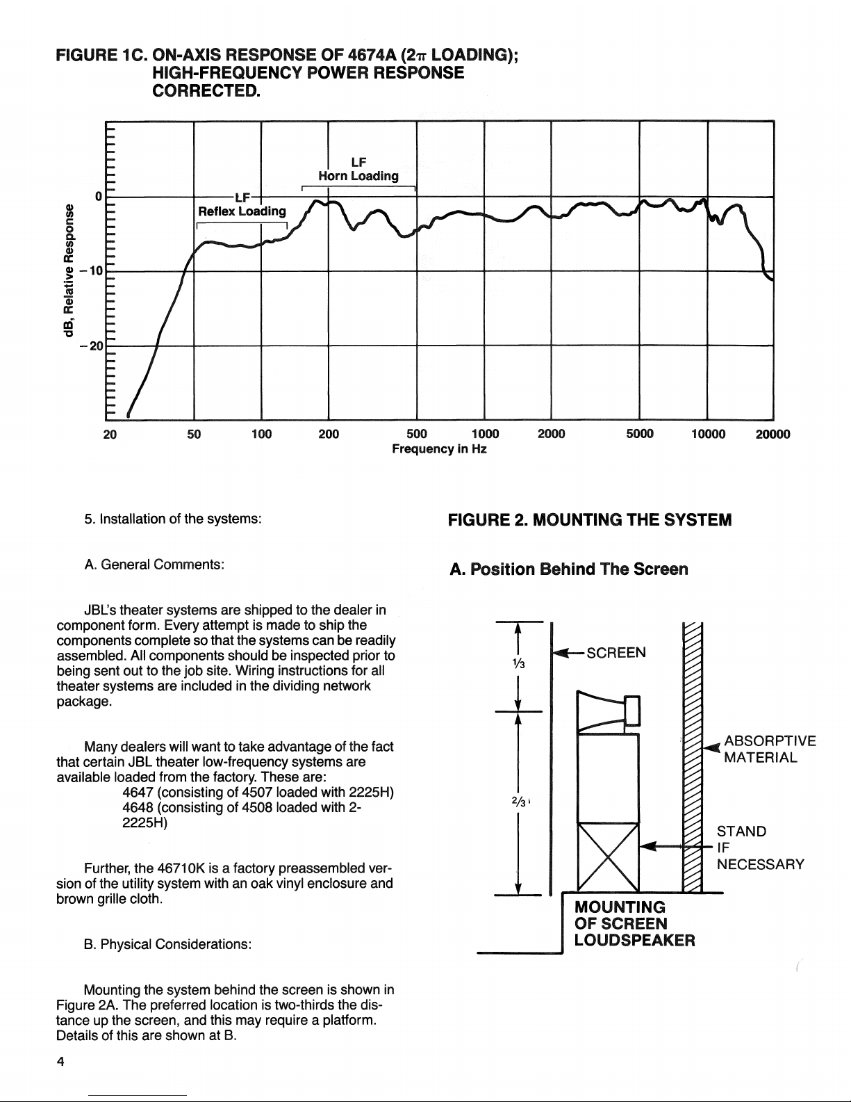
FIGURE 1C. ON-AXIS RESPONSE OF 4674A
(2TT
LOADING);
HIGH-FREQUENCY POWER RESPONSE
CORRECTED.
5. Installation
of
the systems:
FIGURE 2. MOUNTING THE SYSTEM
A. General Comments:
A. Position Behind The Screen
JBL's theater systems
are
shipped
to the
dealer
in
component form. Every attempt
is
made
to
ship
the
components complete so that the systems can
be
readily
assembled.
All
components should
be
inspected prior
to
being sent
out to
the job site. Wiring instructions
for all
theater systems
are
included
in the
dividing network
package.
Many dealers will want
to
take advantage
of
the fact
that certain JBL theater low-frequency systems
are
available loaded from
the
factory. These
are:
4647 (consisting
of
4507 loaded with 2225H)
4648 (consisting
of
4508 loaded with
2-
2225H)
Further,
the
4671
OK
is a
factory preassembled ver-
sion
of
the utility system with
an
oak vinyl enclosure
and
brown grille cloth.
V3
•SCREEN
B. Physical Considerations:
, ABSORPTIVE
' MATERIAL
STAND
IF
NECESSARY
MOUNTING
OF SCREEN
LOUDSPEAKER
Mounting
the
system behind
the
screen
is
shown
in
Figure 2A.
The
preferred location
is
two-thirds the dis-
tance
up the
screen, and this
may
require a platform.
Details
of
this
are
shown
at B.
4
LF
Horn Loading
LF
Reflex Loading
dB,
Relative Response
Frequency in
Hz
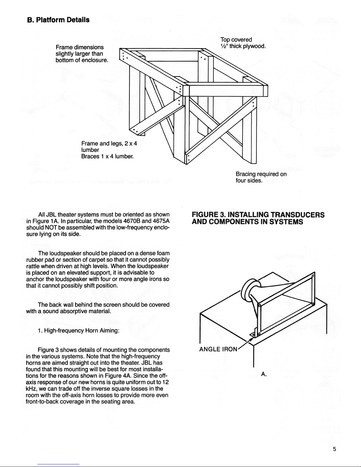
EL Platform Details
Frame dimensions
slightly larger than
bottom of enclosure.
Top covered
V2"
thick plywood.
Frame and legs, 2x4
lumber
Braces 1 x 4 lumber.
Bracing required on
four sides.
All JBL theater systems must be oriented as shown
in Figure 1 A. In particular, the models 4670B and 4675A
should NOT be assembled with the low-frequency enclo-
sure lying on its side.
FIGURE 3- INSTALLING TRANSDUCERS
AND COMPONENTS IN SYSTEMS
The loudspeaker should be placed on a dense foam
rubber pad or section of carpet so that it cannot possibly
rattle when driven at high levels. When the loudspeaker
is placed on an elevated support, it is advisable to
anchor the loudspeaker with four or more angle irons so
that it cannot possibly shift position.
The back wall behind the screen should be covered
with a sound absorptive material.
1.
High-frequency Horn Aiming:
Figure 3 shows details of mounting the components
in the various systems. Note that the high-frequency
horns are aimed straight out into the theater. JBL has
found that this mounting will be best for most installa-
tions for the reasons shown in Figure 4A. Since the off-
axis response of our new horns is quite uniform out to 12
kHz, we can trade off the inverse square losses in the
room with the off-axis horn losses to provide more even
front-to-back coverage in the seating area.
ANGLE IRON
5
A.
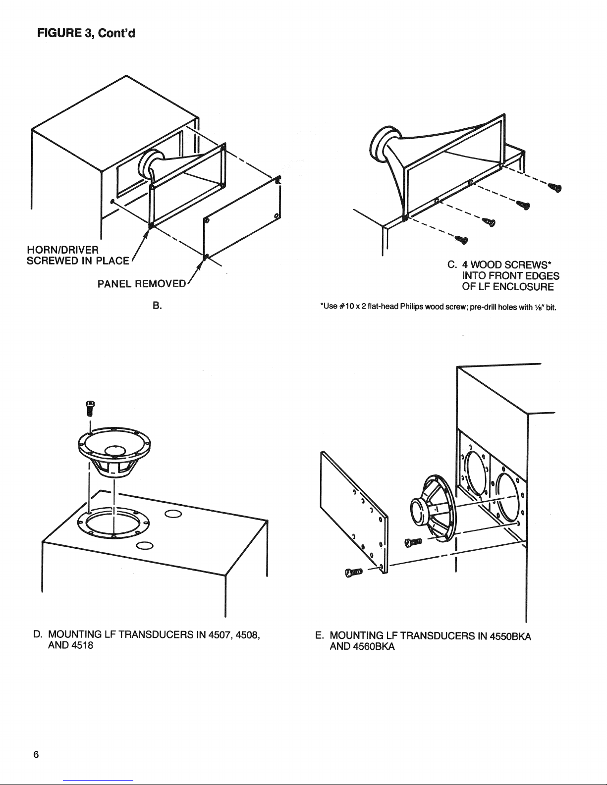
FIGURE 3, Cont'd
6
HORN/DRIVER
SCREWED IN PLACE
PANEL REMOVED
B.
C. 4 WOOD SCREWS*
INTO FRONT EDGES
OF LF ENCLOSURE
"Use #10x2 flat-head Philips wood screw; pre-drill holes with Va" bit.
D. MOUNTING LF TRANSDUCERS IN 4507, 4508,
AND 4518
E. MOUNTING LF TRANSDUCERS IN 4550BKA
AND 4560BKA
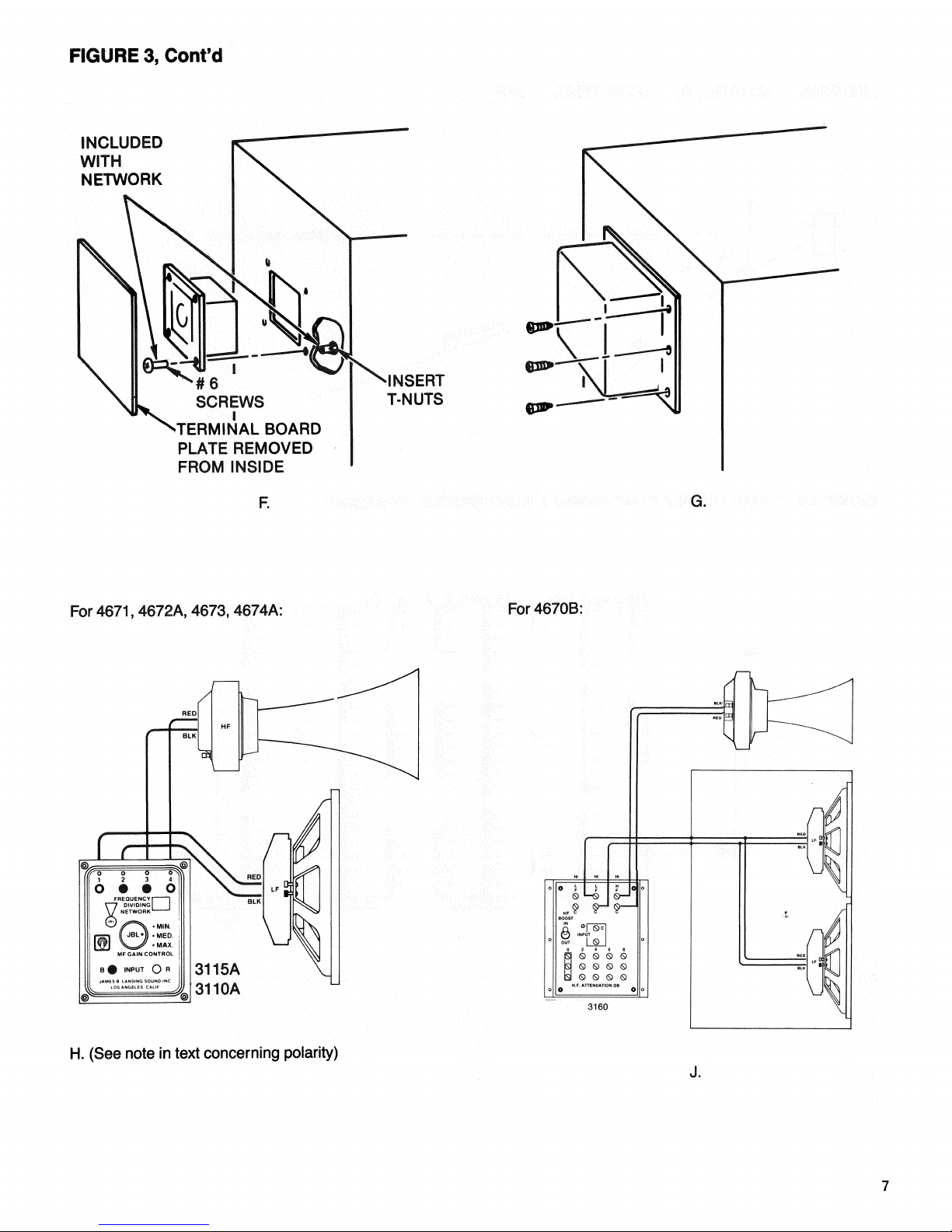
FIGURE 3, Cont'd
H. (See note in text concerning polarity)
INCLUDED
WITH
NETWORK
INSERT
T-NUTS
#6
SCREWS
TERMINAL BOARD
PLATE REMOVED
FROM INSIDE
F.
G.
For 4671,4672A, 4673, 4674A:
For4670B:
3115A
311 OA
J.
7
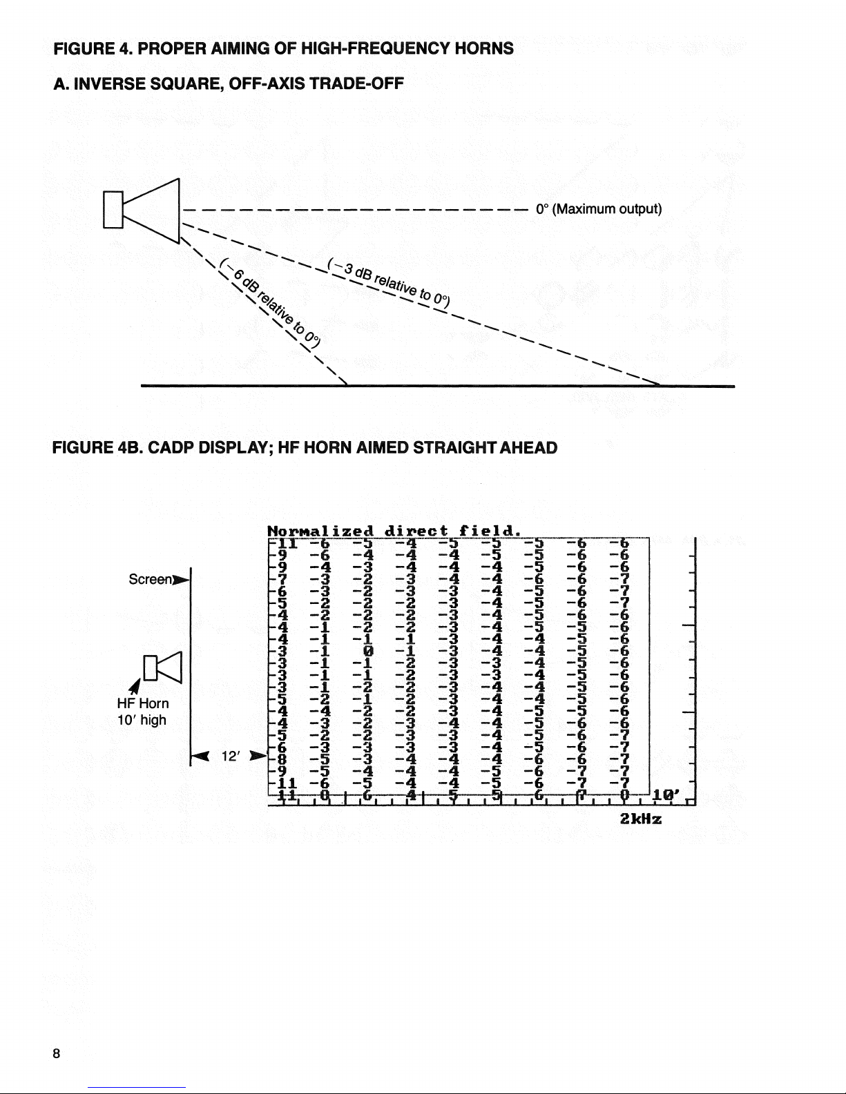
FIGURE 4. PROPER AIMING OF HIGH-FREQUENCY HORNS
A. INVERSE SQUARE, OFF-AXIS TRADE-OFF
0° (Maximum output)
FIGURE 4B. CADP DISPLAY; HF HORN AIMED STRAIGHT AHEAD
Screen!
HF Horn
10'
high
12'
2kHz
8

FIGURE 4C. CADP DISPLAY; HF HORN AIMED 10° DOWN
Screen]
HF Horn
10'high
12'
2kHz
Further evidence of this benefit is shown in the
CADP (see reference) coverage plot shown at B. Here,
the front-to-back variation in coverage is only 5 dB, and
this means that the majority of patrons will receive excel-
lent coverage. Compare this with the coverage shown at
C. Here, we have tilted the high-frequency horn down by
only 10 degrees! The resulting coverage variation has
increased to 8 dB.
Only where there is a pronounced rake (8 degrees
or more) to the floor should the system be angled slightly
upward toward the back
wall.
This can be accomplished
by placing a strip of wood beneath the front edge of the
loudspeaker.
C. Wiring Considerations:
All JBL network and transducer terminals are color
coded so that consistent polarity (phase) of all systems
is assured.
In the following systems, all connections between
transducers and networks should be between like coded
terminals. In other words, red to red, and black to black:
high-frequency section should be wired in reverse
polarity:
4670B
4673
The reason for this has to do with the precise
posi-
tioning of the high-frequency driver with respect to the
low-frequency acoustic center. There is one-half wave-
length shift at the crossover frequency in these systems
which requires the polarity change to maintain proper
summation with the low-frequency section.
Wiring from the projection booth to the screen
loud-
speakers should conform to local codes. The wire gauge
selected should be such that electrical loss at the
loud-
speaker does not exceed 0.5 dB. For most applications
in smaller houses, AWG #12 (2.053 mm) copper wire
will be sufficient. The table shown in Figure 5 shows the
wire resistance for various double runs of copper at var-
ious gauges. For 8-ohm loudspeakers, the total wire
resistance should not exceed 0.552 ohms.
FIGURE 5. TABLE OF WIRE LOSSES
4671
4672A
4674A
In the following systems, the low-frequency section
should be wired red to red and black to black, but the
WIRE RUN (DOUBLE; COPPER)
NO.
10
NO
.12 NO .14
NO
.16
NO.
18
10M
(33')
.02
.032
.05
.08
.125
20M
(66')
.04
.064
.10
.16
.250
30M
(100')
.06
.096
.15
.24
.375
40M
(132')
.08
.128
.20
.32
.500
50M
(165') .1
.160
.25
.40
.625
60M
(200')
.12
.192
.30
.48
.750
FOR
8H LOAD,
LINE
RESISTANCE SHOULD BE 0.552 OR LESS.
9
Nornalized direct field.

The models 4670B and 4675A have 4-ohm low-
frequency sections, and the total wire resistance should
not exceed 0.276 ohms.
C. Systems for Larger Houses:
1.
General Comments:
The class of houses considered here will all have
multichannel systems. Seating capacity may be as little
as 500 and as large as some of the old movie palaces of
yesterday. There are few of the latter left, except in large
metropolitan areas. For the most part, the larger theaters
have been converted into multiplex theaters.
The number of loudspeakers behind the screen will
be either three or five, and there will always be a sur-
round channel consisting of six or more smaller
loud-
speakers arrayed on the side and rear walls.
These systems will be capable of playing Dolby
films,
and third-octave equalization will be employed, as
part of the Dolby equipment, to adjust the system to the
room according to a standard response curve.
In general, the class of audio equipment used in
these installations will be the equal of the finest equip-
ment specified for high-quality sound reinforcement sys-
tems in auditoriums and concert halls.
DO NOT mix different systems in the multichannel
screen loudspeaker array. Not only will there be
dif-
ferences in power handling, there may be polarity
dif-
ferences, and these will adversely affect stereophonic
performance.
We will now cover in detail the requirements for
these systems.
2.
System Recommendations for Large Houses;
500 to 2000 seats; volume 14,000 cubic meters
(500,000 cubic feet):
*Preferred system: Model 4675A (direct radiator
LF)
Power needed for 100 dB: 90 watts
Recommended power amplifier: JBL 6260, one
loudspeaker system per channel (300 watts into 4 ohms)
Characteristics: Broad-band sensitivity 100 dB-
SPL,
one watt at one meter; JBL's most power-flat and
accurate system; uses large Bi-Radial horn for precise
90-by-40 degree pattern control down to 500 Hz; integral
power response correction; extended response down to
45 Hz
For very large houses and for the highest degree of
performance in professional dubbing theaters and
screening rooms, the 4675A-2 may be specified. We rec-
ommend that biamplification be seriously considered
with this system for optimum performance. The broad-
band sensitivity of the 4675A-2 is 103 dB, one watt at
one meter.
* Alternate vented horn systems:
Models 4676B-1 and.4676B-2
Power needed for 100 dB: 80 and 53 watts,
respectively
Recommended amplifier: JBL model 6260, one
channel per loudspeaker system (300 watts)
Characteristics: Mid-band sensitivity, 106 and 109
dB-SPL, respectively; recommended for retrofit in large,
older houses where a complete conversion to all-new
hardware is not feasible. LF response rolls off below 80
Hz
The systems discussed in this section are shown in
Figure 6A. Response curves are shown at B and C.
3. System implementation:
A. Electrical considerations:
The systems intended for larger houses may be
implemented with JBL's 3160 high-level network, with
wiring as shown in Figure 7A through B.
However, for optimum performance, we recommend
biamplification using the JBL model 5234A electronic
dividing network. The 5234A is available with a 500-Hz
card which contains high-frequency power response
correction.
Implementation of biamplification is shown in
Figure 7C.
The chief value of biamplification is the reduction of
intermodulation distortion on peak program signals. Fur-
thermore, larger power amplifiers may be specified for
the LF sections than those indicated for use with the
high-level dividing network.
10

FIGURE 6. SYSTEMS FOR LARGE THEATERS
A.
LINE
DRAWINGS
4675A
4675A-2
4676B-1 4676B-2
PMAX =
300 W
SENSITIVITY:
100 dB,
1 W, 1 M
PMAX =
300 W
SENSITIVITY:
100 dB,
1 W, 1 M
PMAX =
300 W
SENSITIVITY:
106 dB,
1 W, 1 M
PMAX =
300 W
SENSITIVITY:
109 dB,
1 W, 1 M
FIGURE 6B. ON-AXIS RESPONSE, 4675A (2ir LOADING);
HIGH-FREQUENCY POWER RESPONSE CORRECTION ADDED.
dB,
Relative
Response
11
Frequency in Hz

FIGURE 6C. 0N-AX1S RESPONSE OF 4676B-1
(2ir
LOADING);
HIGH-FREQUENCY POWER RESPONSE CORRECTION ADDED.
The
LF
sections
of
these systems
are
four ohms
in
impedance, and that consideration should,
as in the
pre-
vious section, dictate
the
choice
of
wire gauge
for
hook-
up.
It
is
important
in any
biamplified installation
to
include
DC
blocking capacitors
in
output
of
the high-fre-
quency amplifier,
as
shown
in
Figure 7C.
The
capacitor
protects
the
high-frequency driver from
any
inadvertent
DC
or
low-frequency transients which could develop dur-
ing power-up
or
power-down phases
of
amplifier opera-
tion.
Figure
7D
presents a table
of
capacitor sizes
for
various applications.
FIGURE 7. WIRING DIAGRAMS FOR
LARGER SYSTEMS
FIGURE
7A.
For 4675
and
4676 B-1 (See note
in
text concerning
polarity)
12
LF
Horn Loading
LF
Reflex Loading
dB, Relative Response
Frequency in
Hz
3160

FIGURE 7, Cont'd.
FIGURE 7C.
Biamplification
with the 5234A,
Use plug-in 500-Hz
card 52-5222
with high-frequency
power response
equalization
JBL 5234A
LF OUT'
DC BLOCKING
CAPACITOR
FIGURE 7D. BLOCKING CAPACITOR VALUES FOR DRIVER PROTECTION
CAPACITOR
JBL
FOR OPTIMUM RESULTS
VALUE PART AT THESE CROSSOVER
NUMBER
FREQUENCIES*
36 JXF
62772-0360
500 Hz
24 jxF
62772-0240
800 Hz
*160
OPERATION ASSUMED
HF AMPLIFIER
HF OUT
LF AMPLIFIER
BIAMPLIFICATION
FIGURE 7B.
For 4676 B-2
(Note: Splay each HF
horn
221/2°
off center;
total splay is 45°)

B. Physical considerations:
High-frequency components should be mounted as
shown in Figure 8.
FIGURE 8. MOUNTING THE 2360 HIGH-FREQUENCY HORN
BI-RADIAL HORN
LF ENCLOSURE
ALIGN REAR OF 2506
WITH REAR OF
LFENCLOSURE
As indicated in the previous section, the loudspeak-
ers should be positioned about one-third the way up the
screen.
If the screen is flat, as shown in Figure 9A, the
flanking loudspeakers should be toed in slightly. Where
the screen is curved, as shown at B, the loudspeakers
may be positioned normal to the screen at each position.
The high-frequency horns should be placed within 75-
100 mm (3 to 4 in) from the screen.
FIGURE 9. PLACING THE LOUDSPEAKERS BEHIND THE SCREEN
A. FLAT SCREEN
14
2506 ADAPTER
HF DRIVER
VIEW FROM ABOVE

B. CURVED SCREEN
The best possible acoustical loading of the system
to the room is obtained when the loudspeakers are
mounted in a large flat baffle, as shown in Figure 10.
Here,
the 4675A-2 system has been specified for extra
acoustical power output in the 40 Hz to 500 Hz range.
The baffle should not be interrupted, and it should
extend the entire width of the loudspeaker array.
Mechanical details of this baffle are given in Figure 11.
Ideally the baffle should be continuous in a multi-loud-
speaker screen array.
FIGURE 10- PHOTO OF ACADEMY OF MOTION PICTURE ARTS AND SCIENCES SYSTEM
VIEW FROM ABOVE
15

FIGURE
11.
DETAILS OF LARGE FLAT BAFFLE
4'
BY 8' 1" THICK PARTICLE BOARD
2'
by 4' STIFFEN-
ERS MOUNTED AS
SHOWN ON BACK-
SIDE OF BAFFLES
PANELS BOLTED TO
EACH OTHER AND
TO 4508 ENCLO-
SURES,
AS SHOWN.
16
FRONT VIEW
TOP VIEW
ADDED 2 BY 4
BRACES (AT 3
PLACES ON BACK
OF EACH BAFFLE)

D. Surround Systems:
1.
General comments:
While there is little consistent practice in specifying
and implementing surround channels, we can set down
the following general requirements:
a. The total acoustical power delivered by the
ensemble of surround loudspeakers should be
equal to one of the screen channels. There are
probably not many surround systems which
meet this requirement, but it is essential if the full
impact of surround information is to be appreci-
ated.
While a 15-dB headroom factor is a part of
the power calculations for the screen channels, it
may be unreasonable to demand that of the sur-
round channel. Thus, a requirement that the sur-
round channel be able to produce a level in the
house of 95 dB will suffice. In the case of distrib-
uted 200 mm (8 in) loudspeakers, a level of 92dB
is deemed sufficient.
b. The quantity of surround loudspeakers should be
sufficient so the listeners are not aware of any
one of them. This usually means a minimum of
eight: three each on the side walls and two on the
back
wall.
c. The surround loudspeakers should exhibit wide
dispersion so that the entire audience area can
appreciate smooth coverage across the
fre-
quency range.
d.
Surround loudspeakers should be unobtrusive
and not interfere with theater decor. This require-
ment may run counter to some of the acoustical
requirements in that size is related to system
efficiency.
2.
Choosing the right surround loudspeakers:
JBL has recently introduced the model 8325A three-
way system for surround applications. With input power
capacity of 80 watts and a sensitivity of 91 dB, one watt
at one meter, ten to twelve of these systems are a rea-
sonable match for a screen array of 4675A systems.
More than ten may be required for broader coverage in
larger houses.
In larger theaters, the 46120K has been success-
fully used as a surround loudspeaker. This system has a
sensitivity of 97 dB, one watt at one meter, and power
input is 400 watts. Obviously, fewer of these systems
would be required than with the 8325A.
In general, we would recommend the following
quantities of the various surround loudspeakers for rea-
sonable matching with a screen loudspeaker array
consisting of 4675A's:
8325A 10 to 12
4671 or
4671
OK 6 to 8
46120K 6 to 8
Dolby Laboratories has suggested the use of
mul-
tiple 200 mm (8 in) loudspeakers for the surround chan-
nel.
Upwards of 60 such loudspeakers may be used in
this configuration, mounted in groups of six or eight and
arrayed horizontally along the walls. The JBL model
8140 Co-Motional driver is ideal for this application
because of its extremely smooth and wide high-fre-
quency dispersion.
3. Implementation of the surround system:
Figure 12 shows the general mounting for surround
loudspeakers. Note that they cover the back two-thirds
of the house and that they are located one-third the dis-
tance up the walls.
A. SIDE VIEW
D
17
FIGURE 12. LOCATING THE SURROUND
LOUDSPEAKERS
B. TOP VIEW

FIGURE 13. WIRING THE SURROUND LOUDSPEAKERS
Figure 13 shows details of electrical hook-up.
Series-parallel wiring will be necessary to ensure that
each amplifier sees a proper
load.
Most amplifiers today
have a 4-ohm rating, and load impedances anywhere in
the 4 to 8-ohm range are acceptable.
JBL recommends that surround loudspeakers be
individually wired back to the projection booth for ease in
isolating problems and reconfiguring the loudspeakers
for split surround channels. AWG #12 (2.053 mm) cop-
per wire will generally be sufficient for wiring the
surrounds.
E Subwoofer Systems:
1.
Background:
Special low-frequency effects in the motion picture
theater date back to the thirties, but the present interest
dates from Universal's "Sensurround" in the seventies.
Since that time, special low-frequency channels for cov-
ering the range from 20 to 40 Hz have become common
in large theaters, and the Dolby CP200 processing unit
has a summed output below 100 Hz that can be used di-
rectly for driving subwoofer amplifiers.
2.
Implementation:
JBL manufactures the 4645 subwoofer system for
motion picture applications. This system, shown in
Fig-
ure 14A, uses the 2245H 460 mm (18 in) transducer,
which is noted for its low distortion and for its total excur-
sion capability of 19 mm (0.75 in).
FIGURE 14A
4645 SUBWOOFER
PMAX =
300W
SENSITIVITY:
95 dB,
1 W, 1 M
18
8 UNITS =
12 UNITS =
Ail
LEFT
SIDE
RIGHT
SIDE
LEFT
SIDE
RIGHT
SIDE
5.3ft

The following table indicates the acoustical power
output which can be expected in two sizes of theaters.
NUMBER OF MODULES
EFFICIENCY
MAXIMUM
ELECTRICAL
POWER INPUT
ACOUSTIC
POWER
SOUND LEVELS
500-
1000-
1000 SEATS 2000 SEATS
1
2%
300 WATTS 6 WATTS
101 dB
100 dB
2
4%
600 WATTS
24 WATTS
107 dB
106 dB
4
8%
1200 WATTS 96 WATTS
113 dB
112 dB
8
16%
2400 WATTS
384 WATTS 119 dB
118 dB
It is essential that only the most stable amplifiers be
used for subwoofer application. The transducers can be
paralleled for 4-ohm operation.
input capability, and another three dB are due to the
increase in efficiency resulting from mutual acoustical
coupling between transducers.
Substantial sound pressure levels are necessary at
very low frequencies to match the 85 dB reference level
in the theater, as the equal loudness contours shown in
Figure 14B indicate. Note that with each doubling of
transducers, the maximum sound pressure level
increases 6 dB. Three dB are due to doubling the power
Subwoofer loudspeakers should be located fairly
close together, and they should be placed at the inter-
section of a wall and floor. Careful bracing and mounting
on rubber or Neoprene pads may be necessary to
mini-
mize rattling.
FIGURE 14B. ROBINSON-DADSON EQUAL LOUDNESS CONTOURS
F. Acoustical Response: The Concept of
Flat Power Response
While loudspeaker systems are fairly flat on axis,
they tend to narrow considerably in their coverage
angles at high frequencies. Their power response rolls
off naturally. If a loudspeaker maintains fairly constant
horizontal and vertical coverage angles over most of its
frequency range, then flat on-axis response will also im-
ply flat power response. Since about half of the sound
heard in the theater has been reflected at least once, it is
important that loudspeakers exhibit fairly flat power
response if the reproduced sound is to be natural.
19
LOUDNESS
LEVEL (PHON)
SOUND-PRESSURE
LEVEL
IN dB RE 20 N/m
2
FREQUENCY IN Hz
MAF
CURVE

Another consequence
of
using loudspeakers with
flat power response
is
that little system equalization will
be required. Figure
15
illustrates this.
At A, we see the
boundary absorption
in a
typical well-designed theater.
Note that
it is
quite flat over
the
frequency range. High-
frequency losses
due to air
absorption
are
shown
at B,
and typical high-frequency screen losses
are
shown
at
C. When
we add all of
these losses,
we get the
response
shown
at D, and
this
is
exactly
the
acoustical response
we would observe
in the
room
if we
were using a loud-
speaker that
had
flat power response.
FIGURE 15. RESPONSE
IN
THE HOUSE
ROOM BOUNDARY LOSSES
EXPRESSED
IN dB
(TYPICAL)
AIR LOSSES
AT 15
METERS,
50%
RELATIVE HUMIDITY
SUM
OF
CURVES
A,
B, AND C
20
dB, RELATIVE LEVEL
dB, RELATIVE LEVEL
ON-AXIS
SCREEN LOSSES
(15
MIL
THICK VINYL,
8%
OPENING)
dB, RELATIVE LEVEL
dB, RELATIVE LEVEL

Figure 16 shows the standard "house curve" to
which most theater systems are equalized. Note that it
closely resembles the summed curve shown in Figure
15D, indicating that flat power response systems will
require little, if any, added equalization in most houses.
JBL's theater systems using Bi-Radial horns exhibit
essentially flat power response as well as flat on-axis
response. The smaller systems exhibit flat on-axis
response, but their power response rolls off slightly at
high frequencies. JBL's passive dividing networks pro-
vide for a high-frequency boost which effectively makes
any of the systems power-flat at high frequencies. In the
smaller systems, this may be accompanied by a slight
on-axis rise at high frequencies. Nevertheless, we rec-
ommend that some degree of high-frequency boost be
used in all theater applications.
FIGURE 16. ISO STANDARD PLAYBACK RESPONSE
Data from
Figure 15
G.
Model 3152A Field Network Modification:
correcting the normal power response roll-off of the
compression driver. JBL recommends that the boost be
used in all theater systems.
The model 3152A network has been replaced by the
3160.
There are two important differences between the
old and new models. The impedance of the low-fre-
quency section has been changed from eight to four
ohms,
thus providing a better sensitivity match between
the low and high sections. Further, the new network has
a switch which introduces a high-frequency boost for
There are, however, quite a few of the older 3152A
networks in the
field,
and they can be modified to provide
the required boost. Details for this modification are given
in Technical Note Volume 1, Number 5. Figures 17 and
18 outline that modification for your convenience.
FIGURE 17. 3152A NETWORK MODIFICATIONS
3.6 mH
LF
OUT
6.0 mH
: i8sr
• (10 WATT)
4.7 JUF*
(200
VDC)
20a*
(10
WATT)
HF
OUT
A. SCHEMATIC OF MODIFIED NETWORK
* NEW COMPONENTS
JUMPER
WIRE
B. VIEW WITH COVER REMOVED
21
INPUT
12H
13.5
13.5
10£2
13.5 MF
LF LF HF
INPUT
10
WATT, WIRE-WOUND
RESISTORS IN PARALLEL

FIGURE 18. RESPONSE OF MODIFIED 3152A NETWORK
H. Notes on Preventive Maintenance:
Nothing lasts forever; however, a properly specified,
installed,
and operated motion picture sound system
comes as close to beating the odds as anything we know
of. There are a few points of preventive maintenance
which will make the theater operator's life a little more
bearable, and we present them below:
1.
Establish fixed gain and equalization settings and
operating levels in each audio chain, and make abso-
lutely sure that all operating personnel adhere to those
settings. Most high-frequency component failures re-
ported to us from the field can be traced directly to
overdriving those components. Locking type controls on
amplifiers will discourage tampering. The JBL models
6230,
6260, and 6290 amplifiers are available with such
controls.
2.
An experienced technician should regularly check
out each audio chain to ensure that no changes have
been made.
3. Make sure that any changes in third-octave sys-
tem equalization are carried out by an experienced
engi-
neer using the correct measuring instrumentation.
4.
The audience is the first to hear a problem, so
monitor carefully any complaints from patrons. Until you
find out differently, assume that the patron's complaint is
legitimate.
5. Routine replacement of drivers is not generally
recommended; however, over years of operation, a
compression driver diaphragm may simply give in to
metal fatigue. Our current titanium diaphragms are much
less susceptible to this than were older aluminum ones.
22
HF (16ft)
RELATIVE
RESPONSE
(dB)
LF (8ft)
13 dB
10 dB
FREQUENCY

I. JBL THEATER SYSTEMS COMPONENTS
A. 4671:
1-4507
Low Frequency Enclosure
1-2225H Low Frequency Transducer
1-2370
High Frequency Horn
1-2425J High Frequency Driver
1-311 OA Network
B. 4673:
1-4507
Low Frequency Enclosure
1-2225H Low Frequency Transducer
1-2380
High Frequency Horn
1-2445J High Frequency Driver
1-3115A Network
C. 4670B:
1-4508
Low Frequency Enclosure
2-2225H Low Frequency Transducers
1-2380
High Frequency Horn
1-2445J High Frequency Driver
1-3160
Network
D. 4672A:
1-4560BKA Low Frequency Enclosure
1-2225H Low Frequency Transducer
1-2370
High Frequency Horn
1-2425J High Frequency Driver
1-311 OA Network
E. 4674A:
1-4560BKA Low Frequency Enclosure
1-2225H Low Frequency Transducer
1-2380
High Frequency Horn
1-2445J High Frequency Driver
1-3115A Network
F. 4675A:
1-4508
Low Frequency Enclosure
2-2225H Low Frequency Transducers
1-2360A High Frequency Horn
1-2445J High Frequency Driver
1-2506
Mounting Bracket
1-3160
Network
<a.
4675A-2:
2-4508 BKA Low Frequency Enclosures
4-2225J Low Frequency Transducers
1-2360A High Frequency Horn
1 -2445J High Frequency Driver
1-2506
Mounting Bracket
1-3160
Network
•H.4676B-1:
1-4550BKA Low Frequency Enclosure
2-2225H Low Frequency Transducers
1-2360A High Frequnecy Horn
1-2445J High Frequency Driver
1-2506
Mounting Bracket
1-3160
Network
I .4676B-2:
2-4550BKA Low Frequency Enclosures
4-2225J Low Frequency Transducers
2-2365A High Frequency Horns
2-2445J High Frequency Drivers
2-2506 Mounting Brackets
1-3160
Network
23

JBL Professional, 8500 Balboa Boulevard, P.O. Box 2200, Northridge, California 91329
U.S.A.
 Loading...