

Page 1
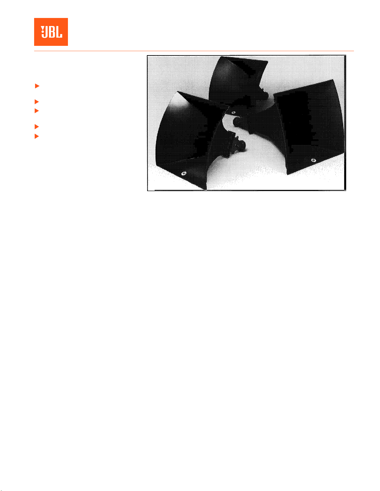
2360A,
Bi-Radial® Constant
Professional Series
Key Features:
Uniform on and off axis
frequency response
Full horn loading to 350 Hz
Precise horizontal and vertical
pattern control
Uncolored sound quality
49 mm (2 in.) throat entry
®
JBL Bi-Radial
to provide uniform on and off axis frequency response from below 500 Hz
to beyond 16 kHz. The horns unique
geometry and relatively tall vertical
mouth dimension ensure precise vertical, as well as horizontal, beamwidth
control throughout the rated frequency band. Since both horizontal
and vertical coverage patterns remain
essentially constant, horn performance may be easily predicted for any
given frequency or orientation. Cluster design, therefore, is simplified and
the need for horn overlapping is minimized. Typical cluster performance
problems such as lobing and comb filter effects are virtually eliminated.
horns¹ are designed
2365A, 2366A
Computer aided design techniques were used to derive the horn contours
in the horizontal and vertical planes. Utilizing sidewall contours based on a
polynomial power series formula, the patented horn design yields smooth
reponse, low distortion, and even coverage. This design avoids the problems
normally associated with horns that feature sharp flare transitions and flat
sidewalls. The Bi-Radial
constant coverage over defined, solid angles.
Three horn models are available with nominal coverage angles of 90° x 40,°
60° x 40° and 40° x 20° ( - 6 dB, Horizontal x Vertical). All three feature 795 mm
5/16
in) square mouth dimensions to further simplify cluster design. In addi-
(31
tion, the 90° x 40° and 60° x 40° horns are identical in length.
Each Bi-Radial
throat that will accept JBL 2446, 2450, or 2485 50 mm (2 in) throat diameter
compression drivers. 25 mm (1 in) throat diameter drivers may be mounted if a
proper horn throat adapter is installed. Mounting tabs are provided on all four
sides of the supplied horn throat and are located just behind the combined
horn/driver center of gravity.
To ensure freedom from resonances, light weight, and superior structural
strength, the horn bell is constructed of heavy duty, 7.5 mm (
fiberglass reinforced plastic. Mounting holes are provided on the top wall of
the bell to facilitate three-point hanging.
®
compound flare configuration of the horn provides
®
constant coverage horn is supplied with a cast aluminum
Coverage Horns
5/16
in) thick,
U.S. Patent No 4,308,932. Foreign patents pending
Page 2
2360A, 2365A, 2366A Bi-Radial® Constant Coverage Horns
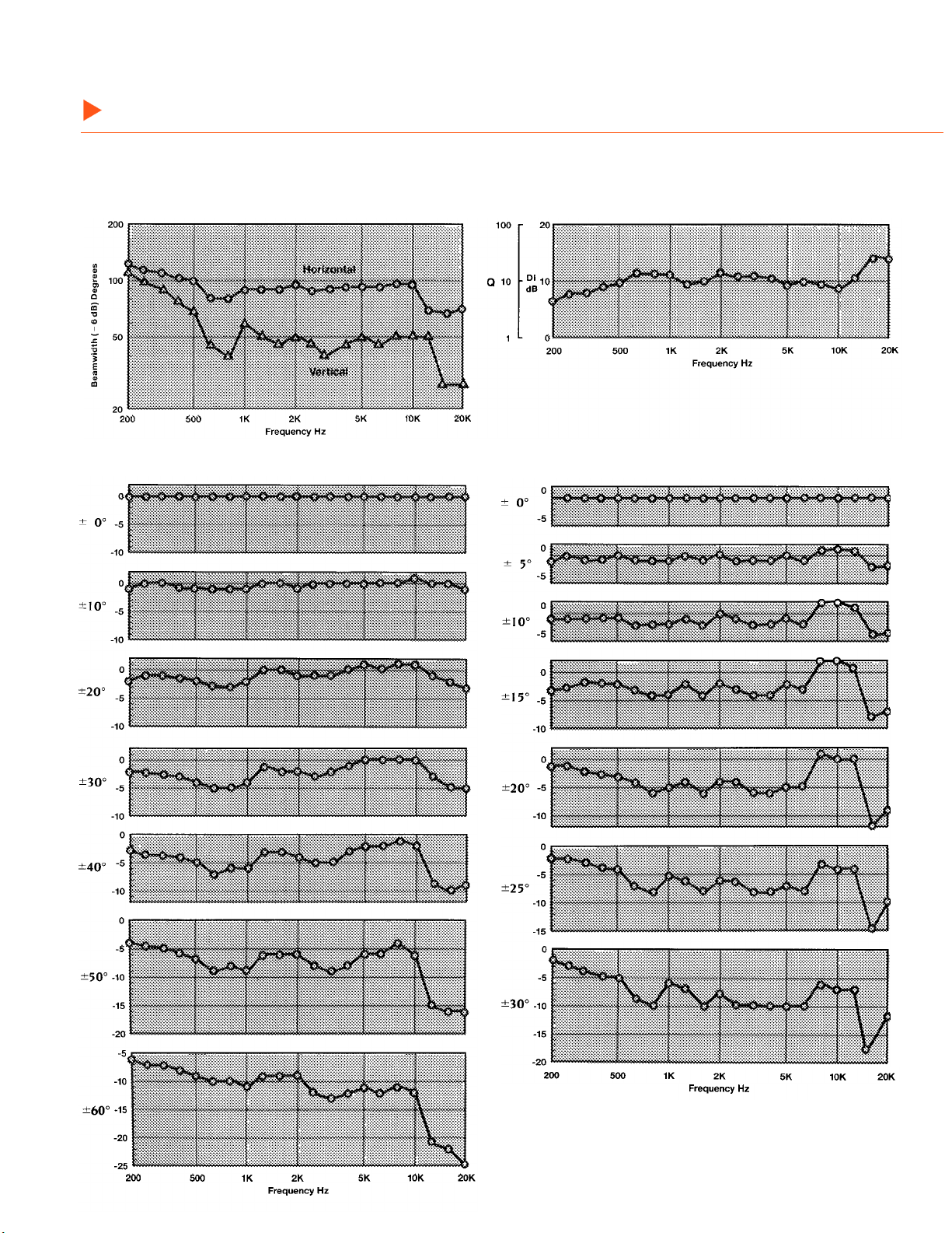
Model 2360A
Beamwidth vs Frequency
Directivity vs Frequency
Horizontal Off-axis Response (Normalized to on-axis)
Vertical Off-axis Response
Page 3
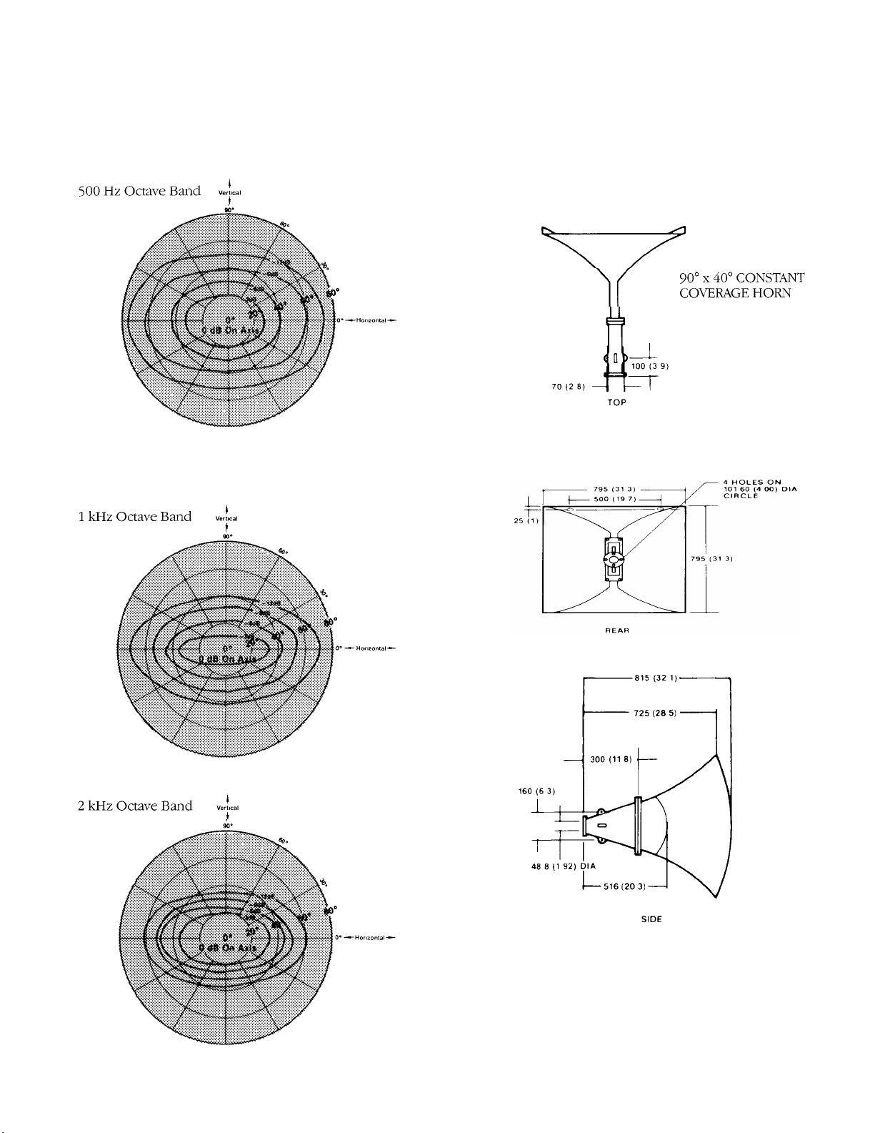
Model 2360A Frontal Isobar Contours
500 Hz octave bandwidth constant sound pressure contours of 0 to
-12 dB in steps of -3 dB. The contours are plotted on polar grid
lines with on axis being the center of the plot. The data was gathered
by taking an octave polar plot at all oblique angles from 0° (horizontal) to 90° (vertical) in steps of 5°
Dimensions are in millimeters.
Dimensions in ( ) are in inches
1 kHz octave bandwidth constant sound pressure contours, Same
conditions as 500 Hz contours.
2 kHz octave bandwidth constant sound pressure contours. Same
conditions as 500 Hz contours. This data may be considered essentially the same as would be observed at 4 kHz and 8 kHz, considering
only the -3, -6, and -9 dB isobars.
Page 4

2360A, 2365A, 2366A, Bi-Radial® Constant Coverage Horns
Model 2365A
Beamwidth vs Frequency
Directivity vs Frequency
Horizontal Off-axis Response
(Normalized to on-axis)
Vertical Off-axis Response
(Normalized to on-axis)
Page 5

Model 2365A Frontal Isobar Contours
500 Hz octave bandwidth constant sound pressure contours of 0 to
- 12 dB in steps of - 3 dB. The contours are plotted on polar grid
lines with on axis being the center of the plot. The data was gathered
by taking an octave polar plot at all oblique angles from 0° (horizontal) to 90° (vertical) in steps of 5°.
Dimensions are in millimeters.
Dimensions in ( ) are in inches.
1 kHz octave bandwidth constant sound pressure contours. Same
conditions as 500 Hz contours.
2 kHz octave bandwidth constant sound pressure contours. Same
conditions as 500 Hz contours. This data may be considered essentially the same as would be observed at 4 kHz and 8 kHz, considering
only the - 3, - 6, and - 9 dB isobars.
Page 6

2360A, 2365A, 2366A Bi-Radial® Constant Coverage Horns
Model 2366A
Beamwidth vs Frequency
Directivity vs Frequency
Horizontal Off-axis Response (Normalized to on-axis)
Vertical Off-axis Response
(Normalized to on-axis)
Page 7

Model 2366A Frontal Isobar Contours
500 Hz octave bandwidth constant sound pressure contours of 0 to
-12 dB in steps of -3 dB. The contours are plotted on polar grid
lines with on axis being the center of the plot. The data was gathered
by taking an octave polar plot at all oblique angles from 0° (horizontal) to 90° (vertical) in steps of 5°.
Dimensions are in millimeters.
Dimensions in ( ) are in inches
1 kHz octave bandwidth constant sound pressure contours. Same
conditions as 500 Hz contours.
2 kHz octave bandwidth constant sound pressure contours. Same
conditions as 500 Hz contours. This data may be considered essentially the same as would be observed at 4 kHz and 8 kHz, considering
only the -3, -6, and -9 dB isobars
Page 8

2360A, 2365A, 2366A Bi-Radial® Constant Coverage Horns
Specifications:
HORN MODEL:
Throw:
Horizontal Coverage
Angle Degrees ( 6 dB):
Average Range:
Vertical Coverage
Angle Degrees ( 6 dB):
Average Range:
Directivity Factor (Q):
Average Range:
Directivity Index (DI):
Usable Low Frequency Limit:
Minimum Recommended Crossover Frequency
(using 2427, 2445, 2450):
(using 2485):
Axial Pressure Sensitivity: Measured on axis in the far field with 1 watt input (2.83 V rms, 8 ohms; 4.0 V rms, 16 ohms) and referred to a 1 meter
distance calculated by inverse square law. Listed sound pressure level (SPL re 20 mPa) represents an average from
630 Hz to 4 kHz using the JBL 2446, 2450, or 2485 driver.
1 Watt/ 1 Meter Axial Sensitivity:
Construction:
Horn Bell:
Horn Throat:
Overall Dimensions: (with throat attached)
Mouth Height:
Mouth Width:
Length:
Net Weight:
Shipping Weight¹:
2360A
Short
90° ( +5°, 20°)
500 Hz 16 kHz
50° (+20°, 22°)
500 Hz 16 kHz
14 (+14, -7)
500 Hz 16 kHz
11.5 dB (+3, 3 dB)
300 Hz
500 Hz
350 Hz
113 dB SPL
Molded reinforced urethane resin.
Aluminum, sand cast (nominal 7.5 mm [
795 mm (31
795 mm (31
815 mm (32
12.2 kg (27 lb)
30.2 kg (66.5 lb)
5/16
in)
5/16
in)
7/64
in)
2365A
Medium
60° (+10°, 10°)
500 Hz 16 kHz
40° ( +18°, 13°)
500 Hz 16 kHz
18 (+7, 5)
500 Hz 16 kHz
12.5 db (+1.5, -1.5)
300 Hz
500 Hz
350 Hz
115 dB SPL
5/16
in] wall thickness).
5/16
795 mm (31
795 mm (31
815 mm (32
11.3 kg (25 lb)
26.2 kg (57.8 lb)
in)
5/16
in)
7/64
in)
2366A
Long
50° (+20°, 10°)
500 Hz 16 kHz
27° ( +8°, 7°)
1000 Hz 16 kHz
28 (+12, -8)
1000 Hz 16 kHz
14.5 dB (+1.5, 1.5 dB)
200 Hz
500 Hz
300 Hz
118 dB SPL
5/16
795 mm (31
795 mm (31
1390 mm (54
16.3 kg (36 lb)
30.8 kg (68 lb)
5/16
45/64
in)
in)
in)
¹Horn and horn throat are packed in one carton
JBL Professional
8500 Balboa Boulevard, P.O. Box 2200
Northridge, California 91329 U.S.A.
A Harman International Company
SS 2360/65/66
CRP 5M
10/96
 Loading...