

JBL 1500, Project Array 1500 Service Manual
Project Array™
1500 Array
Subwoofer
Service Manual
JBL Consumer Products
250 Crossways Park Dr.
Woodbury, New York 11797 Rev0 4/2006

1
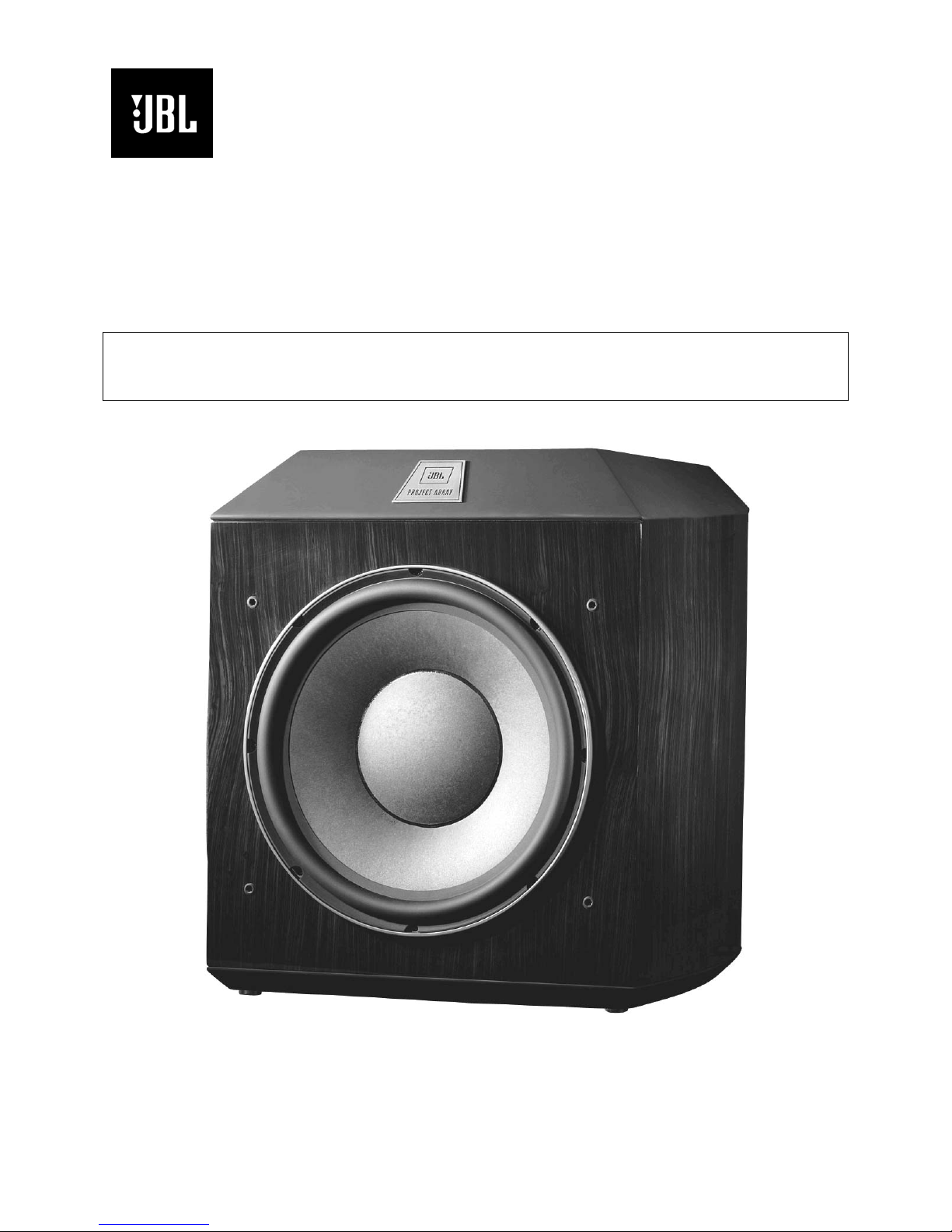
1500 Array Subwoofer
- CONTENTS -
BASIC SPECIFICATIONS ……………. ……..…………..1
PACKING……..……......................................................2
DETAILED SPECIFICATIONS ……….……..…………..3
CONNECTIONS………………………...……..…...…..…5
OPERATION ……..………………….……...…….….…...6
BASIC TROUBLESHOOTING……………………………7
EXPLODED VIEW/PARTS LIST…….….….…………....8
TEST SET-UP AND PROCEDURE….………………….9
BLOCK DIAGRAM….…………………………………….10
ELECTRICAL PARTS LIST……………………………..11
P.C.B. DRAWINGS….……………...........................….16
IC/ T R ANS I S T O R PIN O U T S ..……..….…….….….….….22
SCHEMATICS…………………….………………………23
1500 ARRAY SPECIFICATIONS
General
Output 1000W
Low-Frequency Transducer W1500H 15" Pulp-cone driver
Frequency Response (-3dB) 25Hz – 400Hz, variable
Crossover Frequencies 40Hz-140Hz HP
Port 4" Flared
Dimensions (H x W x D) 23" x 19 -1/2" x 19" (584mm x 495mm x 483mm)
21" (53 3mm) Deep with grille
Weight 125 lb (57kg)
JBL continually striv es to update and improve existi ng pr oduc ts, as well as create new ones. The
specifications and details in this and related JB L publications are therefore subject to c hange without
notice.
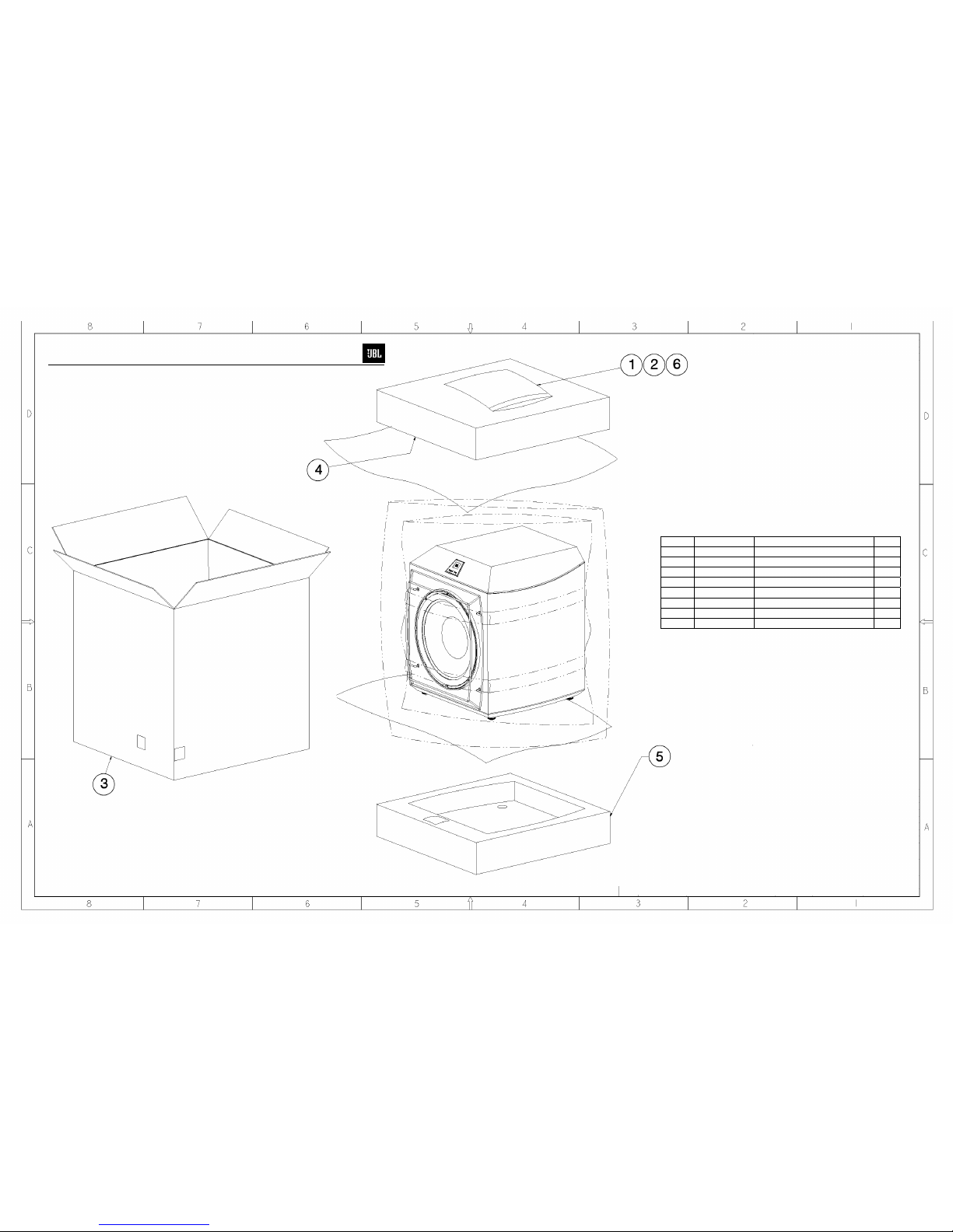
Ref# Part Number Description Qty
1 361041-002 1500 Array Owner’s Manual 1
2 331994-001 JBL Warranty Card 1
3 361408-001 1500 Array Outer Carton 1
4 354374-001 Packing Foam (Top) 1
5 354374-001 Packing Foam (Bottom) 1
6 340805-006 (Plate) Feet 4
2
1500 Array Subwoofer

e
3
1500 Array Subwoofer
1500 Array Powered Sub/ Plate Amp
LINE VOLTAGE Yes/No Hi/Lo Line Nom. Unit Notes
Parameter Specification Unit
Amp Section
Type (Class AB, D, other) D n/a
Load Impedance (speaker) 8 Ohms
Rated Output Power 650 Watts
THD @ Rated Power 0.5 %
THD @ 1 Watt 0.1 %
Dynamic Power 700 Watts
DC Offset 20 mV-DC
Damping factor >20 DF
Input Sensitivity
Input Frequency 100 Hz
Line level input
Signal to Noise
SNR-A-Weighted 100 dBA
SNR-unweighted 95 dBr
SNR rel. 1W-unweighted 70 dBr
Residual Noise Floor 0.5 mVrms
Residual Noise Floor 0.5 mVrms(max)
US 120VAC/60Hz YES 108-132 120 Vrms Normal Operation
EU 230VAC/50-60Hz YES 207-264 230 Vrms Normal operation, MOMS required
Asia 100VAC/50Hz YES 90-110 100 Vrms Normal operation, MOMS required
QA Test
Limits Conditions Notes
Bridge type amplifier, None of the speaker terminals
must be connected to system GND at any time.
Test frequency 100 Hz
3/20 Cycles @ 50 Hz, burst test into 8 Ohms, input
driven with 800mV RMS
Measured at the speaker cable. 500 Watts,
measured at speaker output terminals located at the
amp board.
Single input driven, Ap Zo=600 Ohms, LFE mode,
Volume ctrl. at max.
11.69 mVrms
n/a
n/a
Nominal
593
1 input driven
1
22K filter
0.2
22K filter
Power is the average measurement
of the first four consecutive peaks of
690
the burst signal
100
@ Speaker Outputs
15
Measured at amplifier board
100
Nominal Freq.
±2dB
To 1 Watt
95
Relative to rated power (650 Watts) A-Weighting filter
90
Relative to rated power (650 Watts) 22K filter
65
Relative to 1W Output 22K filter
Volume @max, LFE Mode, using
1
RMS reading DMM/VOM (or A/P)
Volume @max, LFE Mode, w/ A/P
Swept Bandpass Measurement
1
(Line freq.+ harmonics)
Input Impedance
Filters
LP 4th order variable 40-140 Hz
Subsonic filter (HPF) 3rd Ord
LFE Mode Fixed Hz
Features
Line Level output YES
Volume pot Taper (lin/log) LOG --
Variable crossover 40-140 Hz YES
LP Selector switch LFENormal
Phase switch YES -Auto- On-Off selector YES
Input Configuration
Single Line input
Line output configuration
Single Line level output YES
Signal Sensing (ATO)
Auto-Turn-On (yes/no) YES
ATO Input test frequency 50 Hz
ATO Level, Line Input 2.5 mV
ATO Turn-on time 2 seconds
Auto Mute/ Turn-OFF Time 15 minutes
Line Input 10K ohms
Fixed Hz
YES
YES --
n/a
Nominal
± 10
± 10
± 10 LP Mode switch at LFE
functional
functional
functional
functional Pass through from the speaker input section
functional Disables LP filter, intended for LFE
functional Switch located at the back panel
functional Single RCA jack (BLK Color)
Functional
functional
functional
functional
functional
Gain=0dB respect to line level input,
Zo=600 Ohms
Auto - on selection switch in Auto
Amp connected and AC on, then
input signal applied
(T) Time before muting, after input
17
signal is removed
"
"
RCA Line buffered line level output
A Taper
4th Order LP Filter, 2nd order fix and 2nd order
variable.
Single RCA jack (BLK Color)
Auto turn of time (T) must be 10 > T < 17 Minutes
Power on Delay time
ATO mode 4 sec.
ON mode 2 sec.
5
2
After applying the minimum ATO voltage (2mVRMS)
After turning the stand-by knob to ON position
Temperature rise in accessible metal parts should
V
4
1500 Array Subwoofer
Parameter Specification Unit
Transients/Pops
ATO Transient 5 mV-peak
Turn-on Transient 50 mV-peak
Turn-off Transient 50 mV-peak
Efficiency
Efficiency 73 %
Stand-by Input Power 2
Stand-by Input Power 10 Watts
Power Cons. @ 500W 678 Watts
Protection
Thermal Protection YES
DC Offset Protection YES
Line Fuse Rating
Japan 100V & USA- Versions 6.3 Amps Type-T or Slo Blo-250 V UL, PSE Approved
Europe 220-240V 3.15 Amps Type-T, Low breaking capacity-250
QA Test
Limits Conditions Notes
n/a
1V-pk-pk
1V-pk-pk
functional
@ Speaker Output
@ Speaker Output AC Line cycled from OFF to ON
@ Speaker Output AC Line cycled from ON to OFF
500W of output power into rated
70
impedance
@ nominal line voltage, Amp in
3
OFF state, RED LED activated
@ nom. line voltage, Amp in On
8
state, Green LED activated
714
@ nom. line voltage
@1/8 max unclipped Power
-
DC present at Speaker Out leads Relay opens during a DC output condition
Nominal Line voltage
Maximum allowable input power LED in RED,
Class D inactive
Maximum allowable input power under nominal
Input voltage and frequency, in stand-by mode
(HOT or COLD operation, LED GREEN). Class D
active but no stimulus signal applied.
500 Watts into rated impedance 8 Ohms
not exceed 35K rise for domestic version or 30K
rise for European versions (refer to requirements
sheet). Unit is protected for over-temperature
conditions
SEMKO Approved
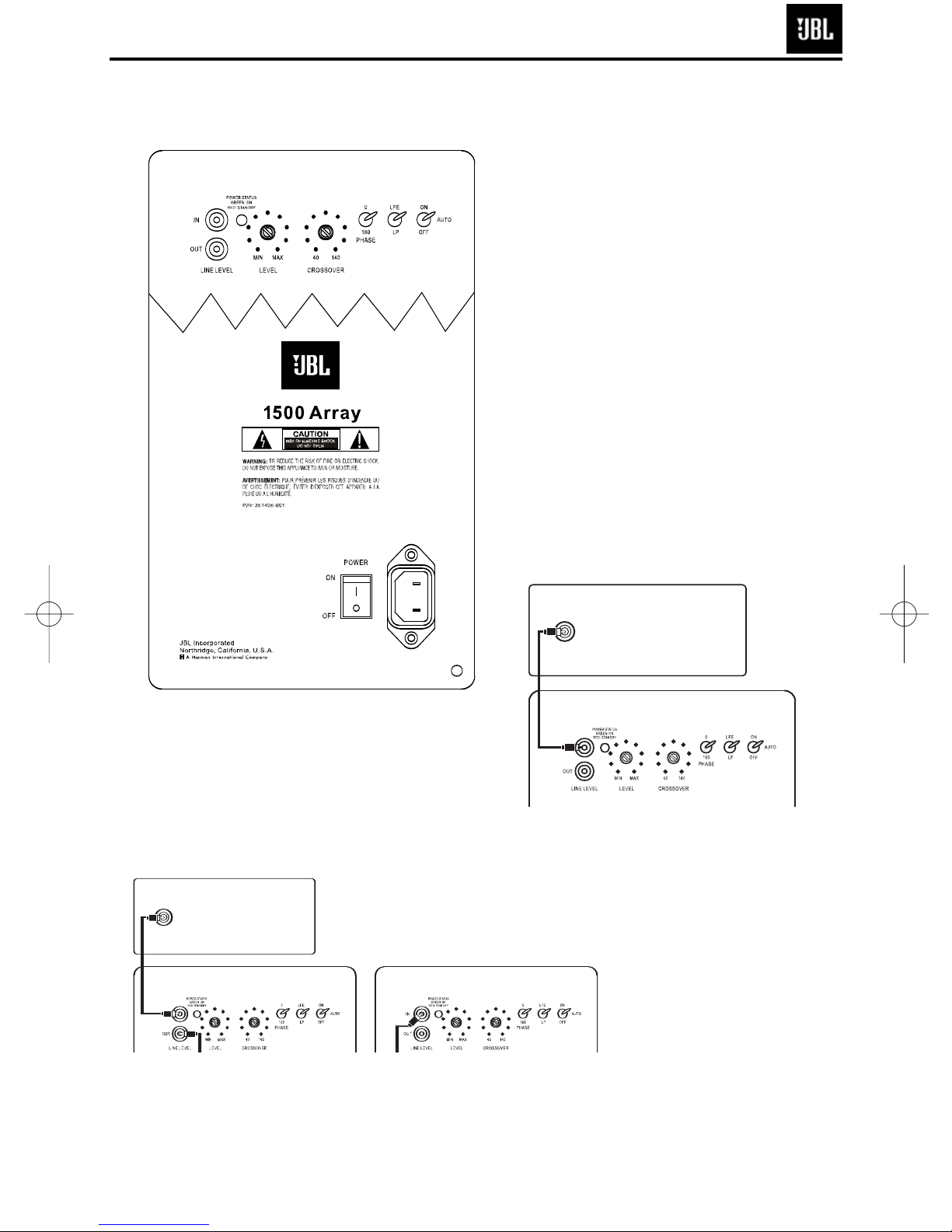
SPEAKER CONNECTIONS
SSuubbwwooooffeerr CCoonnttrroollss aanndd CCoonnnneeccttiioonnss ((11550000 AArrrraayy OOnnllyy))
0
1
2
34
567
8
The 1500 Array includes
a line output. This output
allows you to “daisy chain”
one 1500 Array to multiple
1500 Array subwoofers.
Simply connect the first
subwoofer as described
above and then run a
subwoofer cable from the
line output(s) to the line
input on the next sub.
¡ Line-Level Input
™ Line-Level Output
£ Power Indicator
¢ Subwoofer Level (Volume) Control
∞ Crossover Adjustment
§ Phase Switch
¶ LP/LFE Selector
• On/Off Auto Switch
ª Power Switch
Connection:
If you have a Dolby
®
Digital or DTS
®
receiver/processor with a low-frequencyeffects (LFE) output, set LFE/LP switch to
LFE. If you prefer to use the crossover
built into the 1500 Array, set the LFE/LP
Switch ¶ to LP.
SUBWOOFER OR
LFE OUTPUT
SUBWOOFER OR
LFE OUTPUT
5
1500 Array Subwoofer

Power On
Plug your subwoofer’s AC cord
into a wall outlet. Do not use
the outlets on the back of the
receiver.
Initially set the Subwoofer
Level (Volume) Control
¢ to
the “min” position.
Turn on your sub by pressing
the Power Switch ª on the
rear panel.
Auto On/Standby
With the Power Switch ª
in the “on” position, the Power
Indicator LED £ will remain
backlit in red or green to
indicate the On/Standby
mode of the subwoofer.
RED = STANDBY (No signal
detected, Amp Off)
GREEN = ON (Signal detected,
Amp On)
The subwoofer will automatically enter the Standby
mode after approximately 10
minutes when no signal is
detected from your system.
The subwoofer will then power
ON instantly when a signal is
detected. During periods of
normal use, the Power Switch
ª can be left on. You may turn
off the Power Switch ª for
extended periods of nonoperation, e.g., when you are
away on vacation.
If the Auto Switch
• is in the
“on” position, the subwoofer
will remain on.
Adjust Level
Turn on your entire audio
system and start a CD or movie
soundtrack at a moderate
level. Turn up the Subwoofer
Level (Volume) Control ¢
about halfway. If no sound
emanates from the subwoofer,
check the AC-line cord and
input cables. Are the connectors on the cables making
proper contact? Is the AC
plug connected to a “live”
receptacle? Has the Power
Switch
ª been pressed to
the “on” position? Once you
have confirmed that the subwoofer is active, proceed by
playing a CD or movie. Use a
selection that has ample bass
information.
Set the overall volume control
of the preamplifier or stereo
to a
comfortable level. Adjust
the Subwoofer Level (Volume)
Control
¢ until you obtain a
pleasing blend of bass. Bass
response should not overpower the room but rather
should be adjusted so there is
a harmonious blend across the
entire musical range. Many
users have a tendency to set
the subwoofer volume too
loud, adhering to the belief
that a subwoofer is there to
produce lots of bass. This is
not entirely true. A subwoofer
is there to enhance bass,
extending the response of
the entire system so the bass
can be felt as well as heard.
However, overall balance
must be maintained or the
music will not sound natural.
An experienced listener will
set the volume of the subwoofer so its impact on bass
response is always there but
never obtrusive.
Crossover Adjustments
NOTE: This control will have
no effect if the LP/LFE Selector
Switch ¶ is set to “LFE.” If
you have a Dolby Digital or
DTS processor/receiver, the
Crossover Frequency is set
by the processor/receiver.
Consult your owner’s manual
to learn how to view or change
this setting.
The Crossover Adjustment
Control
∞ determines the
highest frequency at which the
subwoofer reproduces sounds.
If your main speakers can
comfortably reproduce some
low-frequency sounds, set this
control to a lower frequency
setting, between 50Hz and
100Hz. This will concentrate
the subwoofer’s efforts on
the ultradeep bass sounds
required by today’s films and
music. If you are using smaller
bookshelf speakers that do
not extend to the lower bass
frequencies, set the Crossover
Adjustment Control to a higher
setting, between 120Hz and
150Hz.
Phase Control
The Phase Switch § deter-
mines whether the subwoofer
speaker’s pistonlike action
moves in and out with the main
speakers (0˚) or opposite the
main speakers (180˚). Proper
phase adjustment depends
on several variables, such as
subwoofer placement and
listener position. Adjust the
Phase Switch to maximize
bass output at the listening
position.
1500 ARRAY OPERATION
6
1500 Array Subwoofer

7
1500 Array Subwoofer
BASIC TROUBLESHOOTING
If there is low (or no) bass output
• Make sure the connections to the left and right “Speaker
Inputs” have the correct polarity (+ and –).
• Make sure the subwoofer is plugged into an active electrical
outlet.
• Make sure the Power Switch is on.
• In Dolby Digital or DTS modes, make sure your
receiver/processor is configured so that the subwoofer
and LFE output are enabled.
• Adjust the Subwoofer Level Control
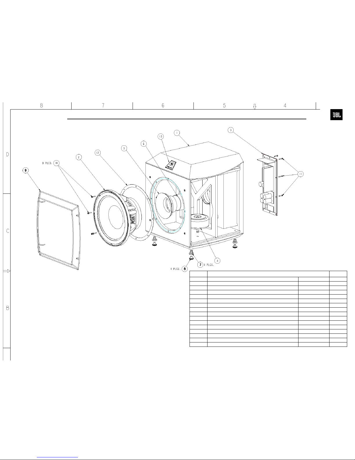
1500 ARRAY MECHANICAL PARTS LIST
Item # Description Part Number Qty
1 CABINET ASSEMBLY-1500 ARRAY Not for Sale 1
2 15" WOOFER-W1500H 353721-001 1
3 AMPLIFIER ASSEMBLY,120V-ARRAY Not for Sale 1
4 POWER TRANSFORMER-1500 ARRAY BG 361407-001 1
5 PORT TUBE -1500 ARRAY 360806-001 1
6 CARBOARD TUBE,4 1/4x4x1/8x6-4338 47909-68 1
7 FOOT,NUT,INSERT,BLK 340805-004 4
8 FOOT,SPIKE,BLK 340805-005 4
9 GRILLE,FRONT, 1500 ARRAY 354507-001 1
10 WOOFER SCREW,10-32 X 1,FIL,PH,BLK ZINC,LCS 804-01110-16 8
11 AMPLIFIER SCREW,8 X 1,PAN,PH,PB,BLK ZINC,LCS 883-41110-16 10
12 GASKET,DRVR,15" 338073-001 1
13 LOGO-JBL 360813-001 1
1500 ARRAY SUB EXPLODED VIEW
X RAY VIEW FOR
ILLUSTRATIVE PURPOSES ONLY
DAMPING MATERIAL NOT SHOWN
8
1500 Array Subwoofer
 Loading...