

JBJ Lighting Varyscan 4 1200 HMI User Manual
JB-lighting Lichtanlagentechnik GmbH
Sallersteigweg 15 D-89134 Blaustein-Wippingen
Telefon ++49(0)7304-9617-0
Telefax ++49(0)7304-9617-99
http://www.jb-lighting.de
english
Bedienungsanleitung
User Manual

2
Varyscan® 4 1200 HMI
Illustration of VS 4 1200HMI..........................................................................................................................3
Back view and position of operating sections...................................................................................4
Unpacking of the Varyscan® Equipment.....................................................................................................4
Put in/ Exchange of the Bulb.........................................................................................................................5
Starting the Equipment..................................................................................................................................5
1. Hang up of Varyscan®........................................................................................................................5
2. Adjustment of Varyscan®...................................................................................................................5
3. Cabling of Varyscan®..........................................................................................................................5
4. Adjustment at DIP-switches .............................................................................................................5
Initialisation Mode...................................................................................................................................6
Test Mode.................................................................................................................................................6
Adjustments at DIP-Switch No.2..........................................................................................................6
1. JB lighting 8 channel drive mode....................................................................................................6
2. 6 channel drive mode (Clay Paky - Goldenscan 3 compatible).................................................7
3. JB-lighting 6 channel drive mode....................................................................................................7
Definition of DIP-switch positions for defined DMX-addresses.............................................................9
Changing of gobos......................................................................................................................................10
GOBO measurements................................................................................................................................10
B Service instructions.................................................................................................................................. 11
Adjustment of the mirror stop............................................................................................................11
Adjustment of the motor brake..........................................................................................................11
Regular Maintenance Performances...............................................................................................12
1. Cleaning of all optical parts...........................................................................................................12
2. Cleaning of ventilation............................................................................................................................12
3. Oiling of rotating gobos .................................................................................................................. 13
General Information about DMX512 record............................................................................................13
Occupation of channels for Varyscan® 4 1200 HMI ............................................................................... 13
Occupation DMX-In / DMX-Out................................................................................................................... 18
Technical data .............................................................................................................................................. 18
Change of Eprom/ Software Update ........................................................................................................ 19
Plan of current circuits for Varyscan® 4 1200HMI...................................................................................20
Occupation of connectors and Jumper....................................................................................................21
List of parts or electronic board of Varyscan® 4 1200 HMI ................................................................... 21
Plan of electronic parts for electronic board of Varyscan® 4 1200 HMI..............................................25
3
Varyscan® 4 1200 HMI
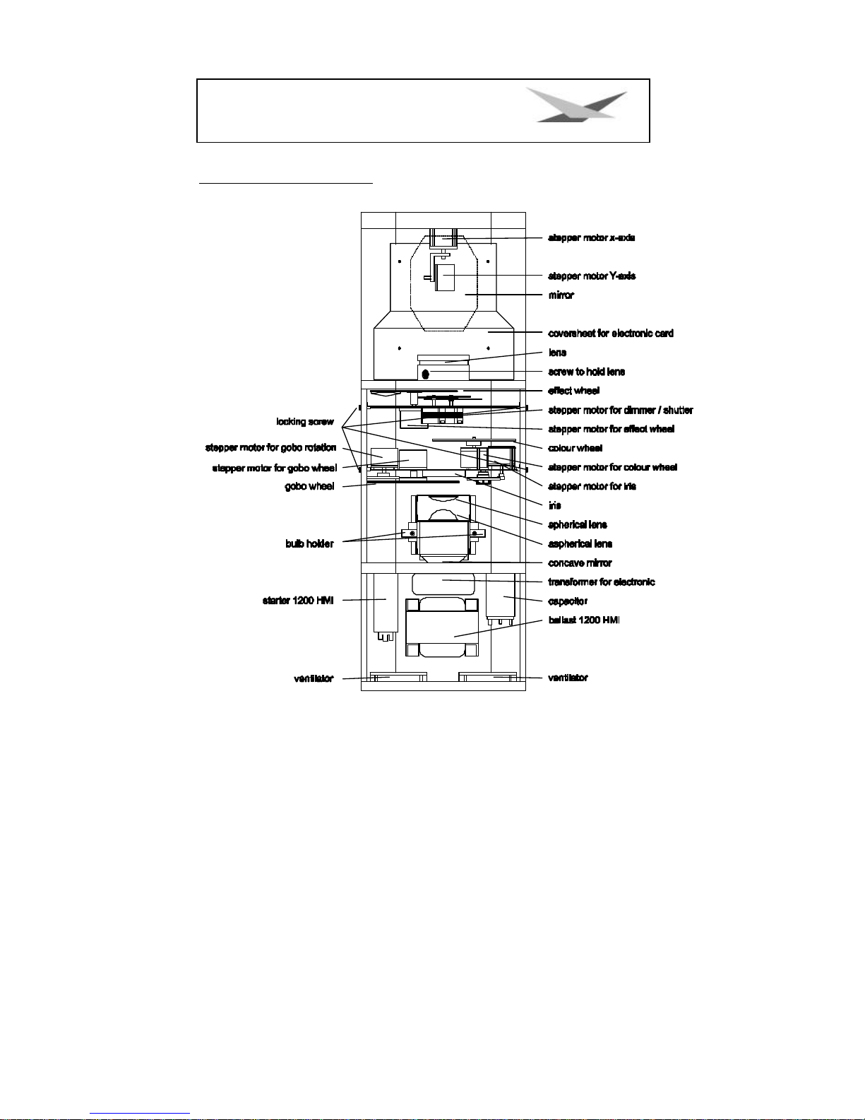
Illustration of VS 4 1200HMI

4
Varyscan® 4 1200 HMI
Back view and position of operating sections
Occupation of DMX-sockets
DMX-in DMX-out
Pin No. signal Colour of wire Pin No. Signal Colour of wire
1 Ground black 1 Ground black
2 DMX - white 2 DMX - white
3 DMX + red 3 DMX + red
4 free 4 not connected
5 +5V green/black 5 not connected
Unpacking of the Varyscan® Equipment
The box contains:
Varyscan® 1200 HMI
operating instructions
Check, if the delivery contains all parts.
Should you notice a damage through transportation, please inform immediately the carriers respectively your
dealer. Also in case of noticing missing parts.

5
Varyscan® 4 1200 HMI
Put in/ Exchange of the Bulb
Warning: Before opening pull out mains plug!
Loosen the screws at the lid of your Varyscan® with a suitable screw-driver and lift the lid (label Varyscan® 4
1200 HMI). You can see the bulb holder in the back third of your
Varyscan® (see outline page 4). Now detach nuts No.1 and No.2 and
remove the bulb from it's holder. Put the new HMI bulb into the holder
and tighten nuts No.1 and No.2 by hand. The point on the glass of the
bulb should on no account point to the concave mirror, respectively to
the lenses (outline page 4), it should point to the base sheet or to the lid.
Take care that the bulb is tightened in the holder.
Warning: Never touch the glass of bulb of the 1200 HMI bulb itself!
An adjustment of the bulb is not necessary.
Starting the Equipment
1. Hang up of Varyscan®
To scoop the optimal functioning of your Varyscan®, you should hang up the spots as high as possible.
2. Adjustment of Varyscan®
All spots should hang in the same angle, i.e. the imagined angle between perpendicular and Varyscan® should
be the same among all Varyscans®
3. Cabling of Varyscan®
Power supply:
A specialist should attach a plug to the open end of the connecting cable, or have the cable connected to 230
volt 50 hertz.
DMX-cabling:
Connect the output of your DMX-controller with the first Varyscan® (controller DMX-out; Varyscan® DMX-in) with
the aid of a 5pole XLR-cabel. Now establish the connection between the Varyscans® with the aid of further
5pole XLR-cables. Make sure that in DMX-out of the last Varyscan® there is a resistor (XLR-plug with a resistance
of 100 Ohm between pin 2 and pin 3) plugged into.
4. Adjustment at DIP-switches
At DIP-switch No.1 and No.2 you have the following possibilities of adjustment:
? initialisation mode
? test mode
? infinitely variable colour changing

6
Varyscan® 4 1200 HMI
? optional channels of Varyscan®
? reset on DMX
? DMX-address
Initialisation Mode
This mode serves for adjustment and basic initialisation of the Varyscan® (carrying-out by producer).
Test Mode
To see the variety of functions of your Varyscan® easily, start the test mode by turning switch 3 off and switch 2
on at DIP-switch No.2. Now plug in your scanner and you will largely see it's functions.
Adjustments at DIP-Switch No.2
Before adjusting DMX-addresses, you have to choose a certain drive mode and then make the right choice of
addresses.
At DIP-switch No.2 you find 4 switches for choosing the following functions.
Infinitely Variable Colour Changing: DIP-switch No.2 switch 1
i.e. the moment this function is turned on, every DMX-factor between 0 and 128 corresponds to an adjustment
of the colour wheel. You can produce not only half colours but 1/3- 2/3 colours or 1/4- 3/4 colours etc. To
choose this function, turn switch 1 at DIP-switch No.2 on.
Is switch 1 on position off, you get only full colours, respectively half colours.
Optional Drive Modes: DIP-switch No.2 switch 2 and 3
You have 3 DMX-channel formats to your disposal, which are explained precisely in the following text.
1. JB lighting 8 channel drive mode
channel 1 x-axis

7
Varyscan® 4 1200 HMI
channel 2 y-axis
channel 3 gobo
channel 4 colour
channel 5 shutter/dimmer
channel 6 iris
channel 7 rotating gobos; positioning and rotation
channel 8 effect wheel
DIP-switch position: DIP-switch No.2 switch 2 and 3 off
2. 6 channel drive mode (Clay Paky - Goldenscan 3 compatible)
channel 1 iris and gobo rotation
channel 2 colour
channel 3 gobo and effect wheel
channel 4 dimmer/shutter
channel 5 x-axis
channel 6 y-axis
DIP-switch position: DIP-switch No.2 switch 2 off, switch 3 on
3. JB-lighting 6 channel drive mode
channel 1 x-motor
channel 2 y-motor
channel 3 gobo
channel 4 colour
channel 5 dimmer/shutter
channel 6 iris/gobo rotation
DIP-switch position: DIP-switch No.2 switch 2 and 3 on
Reset on DMX: DIP-switch No.2 switch 4
If you would like to reset your Varyscan® from your DMX-desk, turn switch 4 on at DIP-switch No.2. Now you have
the possibility to reset your Varyscan®, if you transmit DMX-factor 255 via gobo channel.
If switch 4 at DIP-switch No.2 is turned off, reset on DMX is not possible.

8
Varyscan® 4 1200 HMI
Adjustment of DMX-addresses: DIP-switch No.1 switch 1-9
Depending on the optional drive mode, you have to adjust DMX-addresses as follows. The addressing works by
a binary numeral system and in 6 channel drive mode it has to follow in six steps.
Varyscan® Nr. DMX address
Dip switch setting
1 1
2 7
3 13
4 19
5 25
6 31
7 37
8 43
9 49
10 55
11 61
12 67
In 8 channel drive mode addresses have to be adjusted in 8 steps.
Varyscan® Nr. DMX address
Dip switch setting
1 1
 Loading...