

Page 1

INSTRUCTION MANUAL
DDU
2-Tool Control Unit
Page 2
This manual corresponds to the following reference:
- DDE-9C (100V)
- DDE-1C (120 V)
- DDE-2C (230 V)
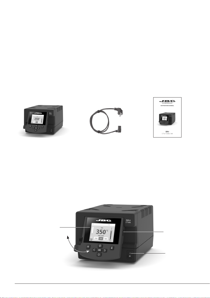
Packing List
The following items are included:
2-Tool
Control Unit .................... 1 unit
Power Cord .................... 1 unit
Ref. 0024077 (100V )
0023717 (120V)
0024080 (230V)
Manual ............................... 1 unit
Ref. 0027023
Features
DDU work simultaneously with up to 2 tools and 1 module + 1 pedal for each tool (peripheral modul
for each tool needed).
2,8” Color TFT screen
USB-A connector
Tilt the display
for easy reading
2
Main Switch
Page 3

Connection Example
para manuales - color gris
DDU 2-Tool Control Unit
Equipotential
connection
USB-B
connector
Stand Cable
Ref. 0 024227
ADS
Stand for
T210 & T245
Handles
T245
General
Purpose
Handle
Module Cable
Ref. 0 024228
Power Soc ket
RJ12 connector
for Robot sy stem
Stand Cable
Ref. 0 024227
DRS
Stand for
DR560
Desoldering
Iron
MSE
Electric Desoldering
Module for DDU & DMU
DR560
Desoldering Iron
Suction
Filter
Re f. 08 21830
To another Peripheral
To Pedal P005
3
Page 4
Compatibility
Select the equipment that best suit your soldering or desoldering needs.
Modular System Peripherals
Control
Unit
DDU
Stand Too l
T210 C210
ADS
DNS
APS AP250 C250
AMS
T245
T470
T210 N C210
T245 N C245
AM120
PA12 0
Cartridge
Range
C245
C120
MSE / MVE MNE P405
ATS AT420
HTS H T420
DSS DS360 C360
DRS DR560 C560
C420
4
Page 5

Port
1
T245
19:29
Sleep
Tool in the stand
Actual Temp. 180º
Delay to hibernation: 29:30
Hibernation
Actual Temp. 25ºC
DDU Work Screen
para manuales - color gris
DDU offers an intuitive user interface which provides quick access to station parameters.
Default PIN: 0105
Status Bar
T245
19:29
ºC
350
Power
Indicator
Displayed if
Temperature
Levels are
Activated
Power
45%
Menu Options
Set the station
parameters
Station Tools Counters
250
Temp levels
350 380
Set the tool
parameters
Port
1
Tool
in use
Station
Information
Change
Port
Display the hours
worked in each cycle
Set the per ipheral
links with the station
ports
Troubleshooting
Station troubleshooting available on the product page at www.jbctools.com
It is possible to
choose the language
from a list.
ResetLanguagePeripherals
Restore station
parameters to default
values
5
Page 6

Advanced Functionalities
It provides detailed graphics of tip temperature and power delivery in real time during
solder joint formation for analysis purposes. This helps you decide how to adjust your
process or which tip to use to obtain the best quality soldering.
Graphics
Designed to avoid thermal shock when soldering Ceramic Chip components like
MLCC, this new and unique feature allows controlling the heating ramp up rate of the
tool to gradually increase the temperature of the component through all the phases of
the soldering process. Up to 25 fully confi gurable soldering profi les can be stored.
Profi les
Get greater quality and control in your production.
JBC Net
Files
Manage your whole soldering process remotely in real time.
For more information see www.jbctools.com/webmanager.html.
Export graphics
Insert a USB flash drive into the
USB-A connector to save your
soldering process in csv format.
Station update
Download the JBC Update File from
www.jbctools.com/software.html
Insert the USB flash drive with the
Update
file downloaded to the station.
System Notifications
The following icons will be displayed on the screen’s status bar.
USB fl ash drive is connected.
Station is controlled by a PC.
Station is controlled by a robot. downloaded to the station.
6
Station sof tware update. Press INFO to
start the process.
Warning. Press INFO for failure description.
Error. Press INFO for failure description,
the type of error and how to proceed.
Page 7

350
ºC
Port
1
Power
45%
Temp levels
T245
250
350 380
19:29
Port
1
T245
19:29
Sleep
Tool in the stand
Actual Temp. 180º
Delay to hibernation: 29:30
T245
Hibernation
Actual Temp. 25ºC
Peripherals
19:29
Pedal PD_a
Module MSE
Port 2-PA
Port
1
T245
19:29
Sleep
Tool in the stand
Actual Temp. 180º
Delay to hibernation: 29:30
Port
1
T245
19:29
Hibernation
Actual Temp. 25ºC
350
ºC
Port
1
Power
45%
Temp levels
T245
250
350 380
19:29
Port
1
T245
19:29
Sleep
Tool in the stand
Actual Temp. 180º
Delay to hibernation: 29:30
T245
Hibernation
Actual Temp. 25ºC
Peripherals
19:29
Pedal PD_a
Module MSE
Peripherals
19:29
Pedal PD_a
Function Extractor
Mode released
Minimum time 0 sec
Back
Peripherals
Port 2-PA Port 2-PA
Port 2-PA
19:29
Pedal None
Module None
Module
MSE_a
None
Port
1
T245
19:29
Sleep
Tool in the stand
Actual Temp. 180º
Delay to hibernation: 29:30
Port
1
T245
19:29
Hibernation
Actual Temp. 25ºC
Peripherals
19:29
Pedal PD_a
Module MSE
Peripheral Set Up
para manuales - color gris
1. After connecting the module, enter the
Peripherals Menu and select the port which
you want to join with the module.
2. Select the module from the list of peripheral
connections. Remember your first connection
is denoted as “a”, the second being “b”, etc.
Peripherals
Pedal None
Module None
Module
MSE_a
None
(e.g. MS _a, M S_b,...).
3. Press Menu or Back to save changes.
Pedal Set Up
1. Enter the Peripherals Menu and select the
port which you want to join to the pedal.
3. Set the pedal function according to your work needs:
Peripherals
Pedal PD_a
Module MSE
Select how the pedal
acts: as Sleep,
Extra ctor (hibernation)
or as a module switch.
Select the activating
19:29
Port 2-PA
Peripherals
Pedal PD_a
Function Extractor
Mode released
Minimum time 0 sec
mode of the pedal
(pressed/released)
*NB: The same can be applied inversely when continually pressing the pedal and releasing to activate.
2. Select the pedal from the list (Note that your
first connection is denoted as “a”, the second
being “b”, etc. (e.g. PD_a, PD_b,...).
Peripherals
Back
Pedal PD_a
Module MSE
19:29
Port 2-PA
Pedal
PD_a
PD_b
None
Set the duration
of the activation
time when pressing
the pedal once*.
For continuous
functioning keep the
pedal pressed.
19:29
Port 2-PA
19:29
Port 2-PA
7
Page 8

Port
1
T245
19:29
Sleep
Tool in the stand
Actual Temp. 180º
Delay to hibernation: 29:30
Port
1
T245
19:29
Hibernation
Actual Temp. 25ºC
Port
1
T245
19:29
Hibernation
Actual Temp. 25ºC
Operation
The JBC Most Efficient Soldering System
Our revolutionary technology is able to recover tip temperature extremely quickly. It means the user
can work at a lower temperature and improve the soldering quality. The tip temperature is further
reduced thanks to the Sleep and Hibernation modes which increase up to 5 times the life of the tip.
3. Hibernation1. Wor k 2. Sleep
Long period
in the stand
When the tool is lifted from
the stand the tip will heat up
to the selected temperature.
19:29
T245
ºC
350
Temp levels
250
Power
45%
350 380
Tools Menu:
· Adjust temperature limits and
cartridge.
· Set temperature levels.
8
Port
When the tool is in the stand,
the temperature falls to the
preset Sleep temperature.
Sleep
Tool in the stand
Actual Temp. 180º
Delay to hibernation: 29:30
1
Tools Menu:
· Set Sleep temperature.
· Set Sleep delay.
(from 0 to 9 min or no Sleep)
T245
After longer periods of
inactivity, the power is cut off
and the tool cools down to
room temperature.
19:29
Port
T245
Hibernation
Actual Temp. 25ºC
1
19:29
Port
1
Tools Menu:
· Set Hibernation delay.
(from 0 to 60 min or no
hibernation)
Page 9

Language
Mode
Station Settings
Tool Settings
Counters
Reset
Exit
Basic
Soldering-Assistant
Back
Mode
Back
Language
Mode
Station Settings
Tool Settings
Counters
Reset
Exit
Basic
Soldering-Assistant
Back
Mode
Back
Language
Mode
Station Settings
Tool Settings
Counters
Reset
Exit
Language
Mode
Station Settings
Tool Settings
Counters
Reset
Exit
C210009
Cartridge
Back
Language
Mode
Station Settings
Tool Settings
Counters
Reset
Exit
C245907
Cartridge
Back
USB Connector
para manuales - color gris
Download the latest software from our website to improve your soldering station at
www.jbctools.com/software.html.
JBC Web Manager Lite
www.jbctools.com/manager.html
Manage and monitor as many stations as your PC can handle by using JBCs Web Manager
Lite. Note: Data can be exported to another PC.
Cable USB A-B
USB
Hub
JBC Web
Manager
any JBC
station
Manager Settings
Change settings for a
group of JBC stations at
the same time.
Register Settings
Create graphs of the
soldering process in
real time showing power
and temperature data.
9
Page 10

Safety
- Do not use the units for any purpose other than soldering or rework. Incorrect use may cause fire.
- The power cord must be plugged into approved bases. Be sure that it is properly grounded before
use. When unplugging it, hold the plug, not the wire.
- Do not work on electrically live parts.
- The tool should be placed in the stand when not in use in order to activate the sleep mode. The
soldering tip or nozzle, the metal part of the tool and the stand may still be hot even when the station
is turned off. Handle with care, including when adjusting the stand position.
- Do not leave the appliance unattended when it is on.
- Do not cover the ventilation grills. Heat can cause inflamable products to ignite.
- Avoid flux coming into contact with skin or eyes to prevent irritation.
- Be careful with the fumes produced when soldering.
- Keep your workplace clean and tidy. Wear appropriate protection glasses and gloves when working
to avoid personal harm.
- Utmost care must be taken with liquid tin waste which can cause burns.
- This appliance can be used by children over the age of eight and also persons with reduced physical,
sensor y or mental capabilities or lack of experience provided that they have been given adequate
supervision or instruction concerning use of the appliance and understand the hazards involved.
Children must not play with the appliance.
- Maintenance must not be carried out by children unless supervised.
It is imperative to follow safety guidelines to prevent electric
shock, injury, fire or explosion.
Maintenance
Before carrying out maintenance or storage, always allow the equipment to cool.
- Clean the station screen with a glass cleaner or a damp cloth.
- Use a damp cloth to clean the casing and the
tool. Alcohol can only be used to clean the
metal parts.
- Periodically check that the metal parts of the
tool and stand are clean so that the station
can detect the tool status.
- Maintain tip surface clean and tinned prior to
storage in order to avoid tip oxidation.
Rusty and dirty surfaces reduce heat transfer
to the solder joint.
- Periodically check all cables and tubes.
- Replace a blown fuse as follows:
1. Pull of f the fuse holder and remove the
fuse. If necessar y use a tool to lever it off.
Clean periodically
2. Press the new fuse into the fuse holder
and replace it in the station.
Fuse
Fuse Holder
- Replace any defective or damaged pieces. Use original JBC spare parts only.
- Repairs should only be performed by a JBC authorized technical service.
10
Fuse holder
Page 11

Safety
para manuales - color gris
It is imperative to follow safety guidelines to prevent electric
shock, injury, fire or explosion.
- Do not use the units for any purpose other than soldering or rework. Incorrect use may cause fire.
- The power cord must be plugged into approved bases. Be sure that it is properly grounded before
use. When unplugging it, hold the plug, not the wire.
- Do not work on electrically live parts.
- The tool should be placed in the stand when not in use in order to activate the sleep mode. The
soldering tip or nozzle, the metal part of the tool and the stand may still be hot even when the station
is turned off. Handle with care, including when adjusting the stand position.
- Do not leave the appliance unattended when it is on.
- Do not cover the ventilation grills. Heat can cause inflamable products to ignite.
- Avoid flux coming into contact with skin or eyes to prevent irritation.
- Be careful with the fumes produced when soldering.
- Keep your workplace clean and tidy. Wear appropriate protection glasses and gloves when working
to avoid personal harm.
- Utmost care must be taken with liquid tin waste which can cause burns.
- This appliance can be used by children over the age of eight and also persons with reduced physical,
sensor y or mental capabilities or lack of experience provided that they have been given adequate
supervision or instruction concerning use of the appliance and understand the hazards involved.
Children must not play with the appliance.
- Maintenance must not be carried out by children unless supervised.
11
Page 12

Notes
12
Page 13

Notes
para manuales - color gris
13
Page 14

Notes
14
Page 15

Specifications
para manuales - color gris
DDU
2-Tool Control Unit
Ref.: DDE-9C 100V 50/60Hz. Input fuse: T5A. Output: 23.5V
Ref.: DDE-1C 120V 50/60Hz. Input fuse: T4A. Output: 23.5V
Ref.: DDE-2C 230V 50/60Hz. Input fuse: T2A. Output: 23.5V
- Output Peak Power: 150W per tool
- Temperature Range: 90 - 450 °C / 190 - 840 °F
- Idle Temp. Stability (still air): ±1.5ºC / ±3º F / Meets and exceed IPC J-STD-001F
- Temp Accuracy: ±3% (using reference cartridge)
- Temp Adjustment: ±50ºC / ±90ºF Through station menu setting
- Tip to Ground Voltage/Resistance: Meets and exceed
ANSI/ESD S20.20-2014 IPC J-STD-001F
- Ambient Operating Temp: 10 - 50 ºC / 50 - 122 ºF
- Connections: USB-A / USB-B / Peripherals connectors
RJ12 connector for Robot
- Control Unit Dimensions/Weight: 148 x 232 x 12 0 mm / 3.82 kg
(L x W x H) 5.8 x 9.1 x 4.7 in / 8.41 lb
- Total Package: 258 x 328 x 208 mm / 4.3 kg
10.15 x 12.9 x 8.1 in / 9.5 lb
Complies with CE standards.
ESD safe.
15
Page 16

Warranty
para manuales - color gris
JBC’s 2 year warranty covers this equipment against
all manufacturing defects, including the replacement
of defective parts and labour.
Warrant y does not cover product wear or misuse.
In order for the warranty to be valid, equipment must
be returned, postage paid, to the dealer where it was
purchased.
Get 1 extra year JBC warra nty by registering here:
https://www.jbctools.com/productregistration/
within 3 0 days of purchase.
This product should not be thrown in the garbage.
In accordance with the European directive 2012/19/EU, electronic equipment at the end of its life must
be collected and returned to an authorized recycling facility.
0027023 - 0522
 Loading...