

Page 1
™
LoMax
CASE & 3:1 GEAR SET
Manufactured by JB CONVERSIONS, INC.
Phone: 337-625-2379
Installation Instructions for the
GM NP205 Transfer Case
Part No. 2800
Instruction Rev: 2007.08.16
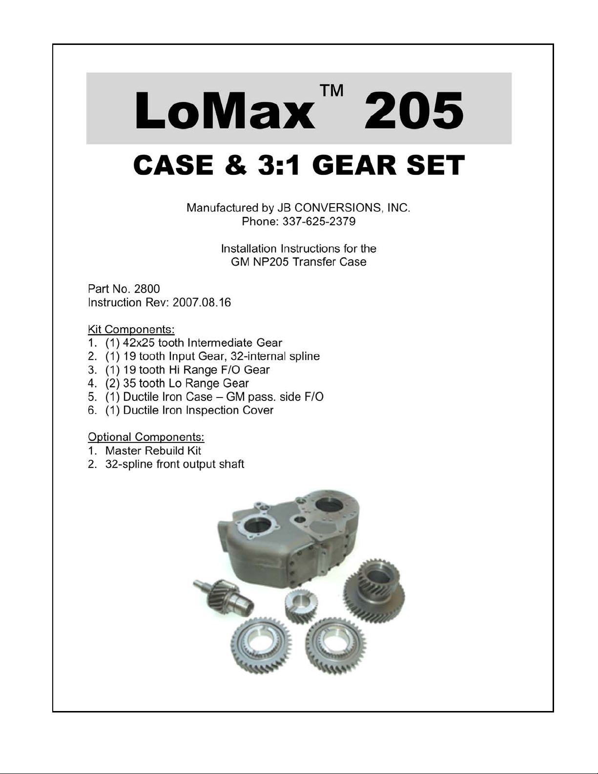
Kit Components:
1. (1) 42x25 tooth Intermediate Gear
2. (1) 19 tooth Input Gear, 32-internal spline
3. (1) 19 tooth Hi Range F/O Gear
4. (2) 35 tooth Lo Range Gear
5. (1) Ductile Iron Case – GM pass. side F/O
6. (1) Ductile Iron Inspection Cover
Optional Components:
1. Master Rebuild Kit
2. 32-spline front output shaft
205
Page 2
LoMax™ 205 – Case and 3:1 Gear Set
Instructions:
1. Drain th e tr an sf er case and re mo v e th e shift ra i l lin k age plate.
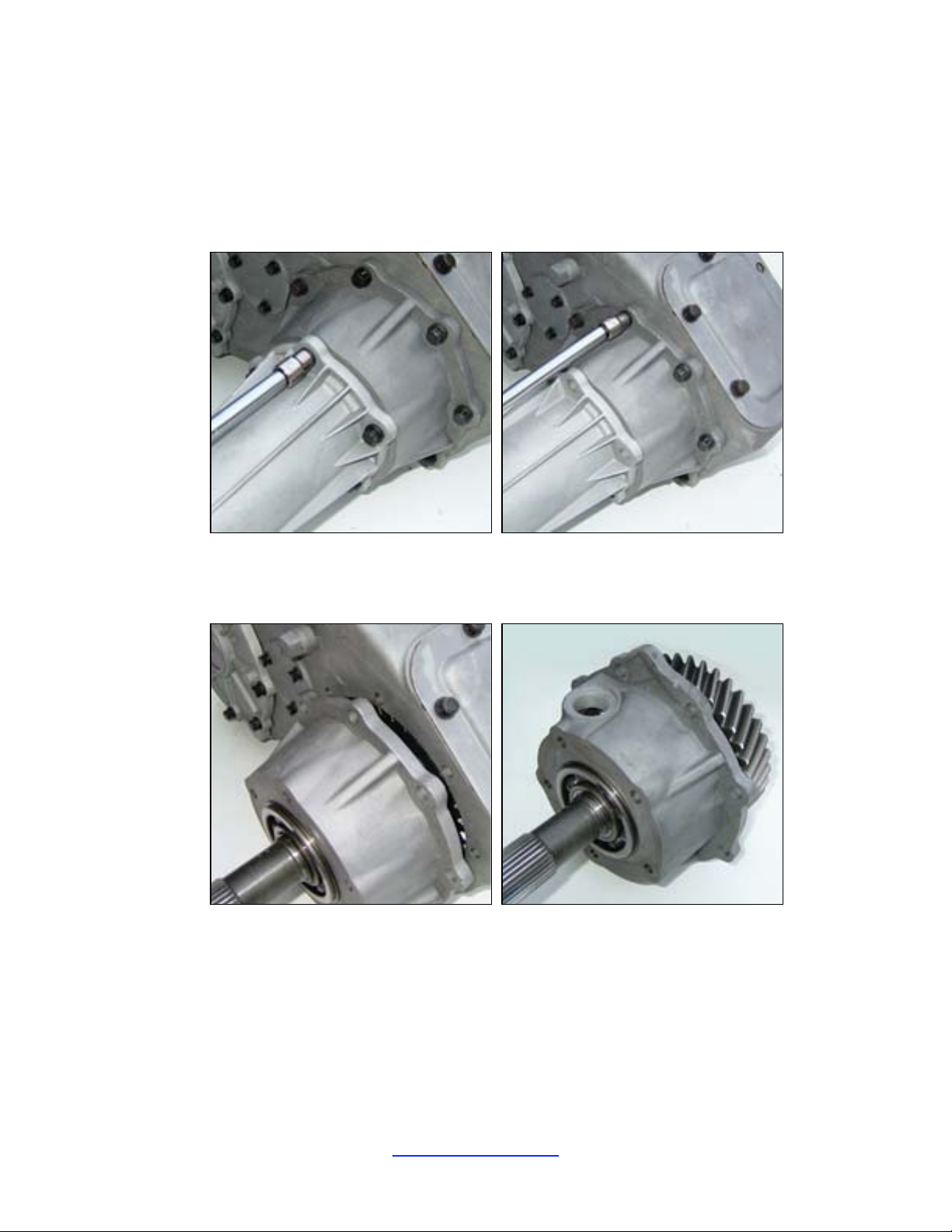
2. Remove the locknut ret aining the front output fla nge followed by the flange itself.
3. Remove the rear tail cone. Remove the bolts holding the rear bearing retainer to the main case. Do
not remove the snap ring on the rear output shaft located at the bearing.
4. Pull the rear output shaft and rear retainer out of the main case. The sli der ring can be pulled out
the case at this point. The shift fork will remain in the case for now.
5. Remove the snap ring from the input shaft. Push or tap the input shaft in toward the case. Remove
it completel y after it has passed through the front bearing. Remove the bearing by tapping it
outward from within the case.
JB Conversions, Inc. Page 1
337-625-2379
337-626-8365 fax www.jbconversions.com
Page 3
LoMax™ 205 – Case and 3:1 Gear Set
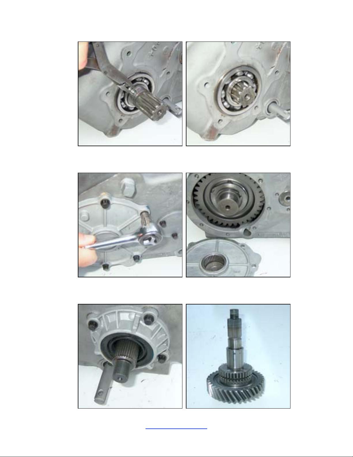
6. Remove the bolts holding the aluminum rear bea ring retainer and the steel intermediate shaft cover
plate. Remove the retainer and cover plate.
7. Remove the four bolt s hol ding the front bearing retaine r to the case. Remove the front output
shaft/gear assembly from the case by tapping it rearward from the front of the case.
JB Conversions, Inc. Page 2
337-625-2379
337-626-8365 fax www.jbconversions.com
Page 4
LoMax™ 205 – Case and 3:1 Gear Set
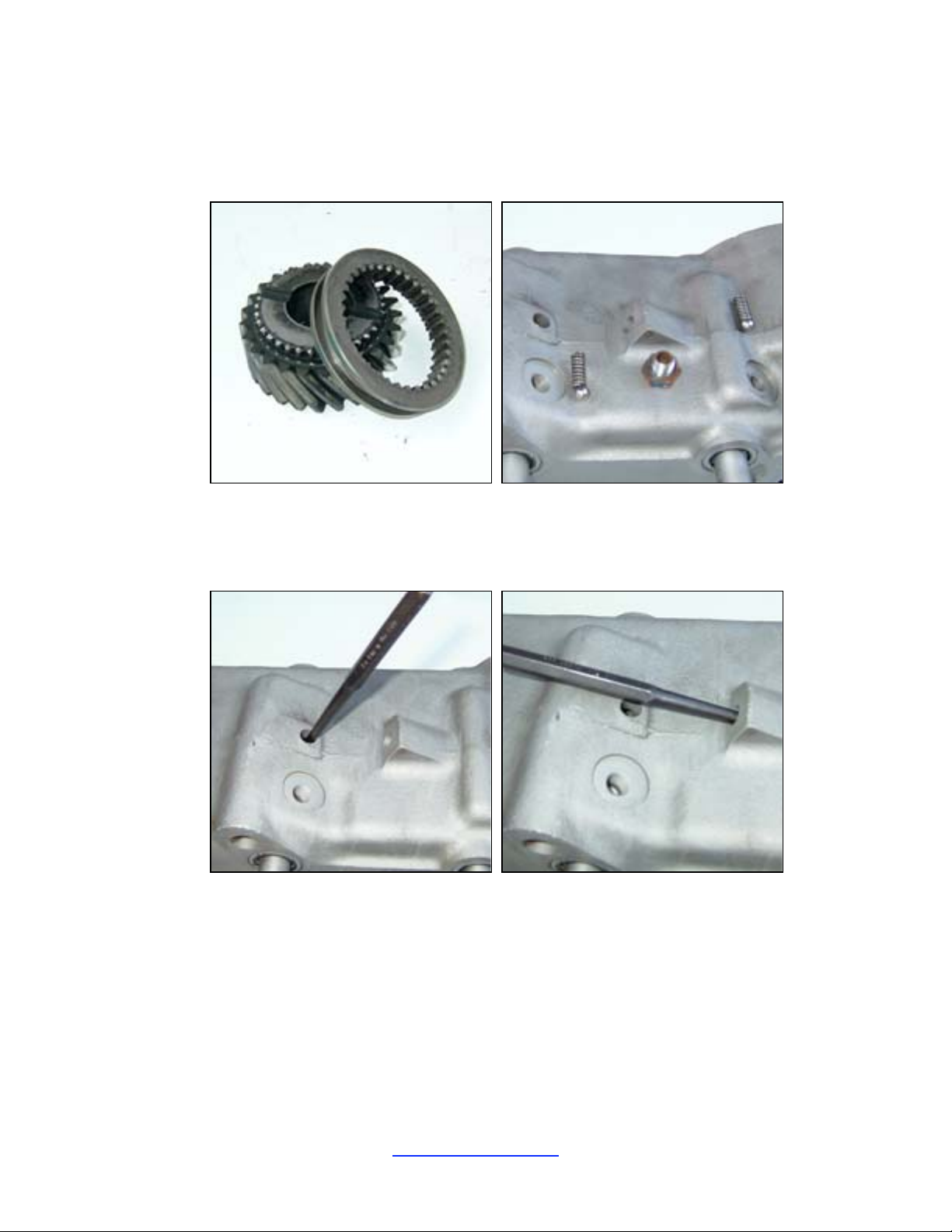
8. Remove the slider ring and the high range front output gear from the case. Then remove the two
hex caps in the top of the ca se followed by the springs and dete nt balls. You can use a magnet and
punch to remove the balls which are located below the springs.
9. Use a punch to drive out the two ” shift rail pin access hole plugs . T hey will fall into the case
and can be removed and disca r ded. You may need to move the shift rails to line up the roll pins
with the holes in the case. Use a small tipped punch to drive the roll pins inward and out of both
shift forks.
10. Remove the short shi ft rail followed by the long shift rail. You may to rotate the rails either
directi on while pulling them through the forks. Steady each fork from within the case as you pull
the rail from outsi de the case.
JB Conversions, Inc. Page 3
337-625-2379
337-626-8365 fax www.jbconversions.com
Page 5
LoMax™ 205 – Case and 3:1 Gear Set
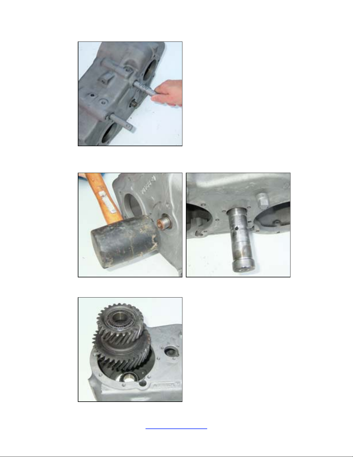
11. Remove the idler shaft nut and washer.
12. Use a punch or dead blow hammer to drive the idler s haft from the case.
13. Move the intermediate gear over to the side and lift it out of the case.
JB Conversions, Inc. Page 4
337-625-2379
337-626-8365 fax www.jbconversions.com
Page 6
LoMax™ 205 – Case and 3:1 Gear Set
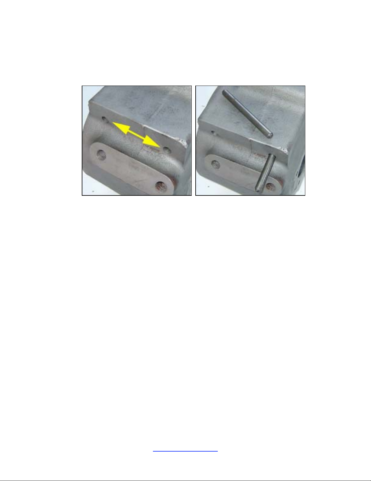
14. It is recommended to ins tall new bearings and races into the new LoMax intermediate gea r. You
will need to retain the internal sleeve located between the two tapered roller bearings. Also, keep
your intermed iate gear shims. A suppleme ntal shim pack is include d with the LoMax kit for use if
necessary.
15. Drive out the two plugs in the side of the case. Slide out th e two long rail pins.
JB Conversions, Inc. Page 5
337-625-2379
337-626-8365 fax www.jbconversions.com
Page 7
LoMax™ 205 – Case and 3:1 Gear Set
Reassembly:
1. Install new bearing races into the intermediate gear.
2. Lay the new LoMax case on the work bench with the front side fac ing up.
3. Place the new intermediate gear onto the tapered roller bearing.
4. Place the steel s leeve onto the top of the bearing. Place the original shims onto the top of the
sleeve. Add the a dditional shims onto the top of the original shims. This will intentionally yield
too much end play.
5. Plac e the 2
intermediate gear/bearings into the case via the inspection opening.
nd
tapered roller bearing into the top race in the intermediate gear. Slide the
JB Conversions, Inc. Page 6
337-625-2379
337-626-8365 fax www.jbconversions.com
Page 8
LoMax™ 205 – Case and 3:1 Gear Set
6. Move the case to the edge of the be nch so that the intermediat e shaft can be pushed up through the
case. Pushing the shaft up from below allows you to look into the bore to check alignment of the
sleeve and shims a s t he inte rm ediate shaft passes through t hem . It is easy to use a punch or
screwdriver to move the shims and/or sleeve as needed to line up with the shaft as it is pushed up
through the gear .
7. When the intermediate shaft is as far in as possible (by hand), turn the case upright and use a dead
blow hammer to knock the intermediate shaft in the rest of the wa y.
8. Do not seal the cover plat e with RTV until the final end play setting is achieved. The cover should
be torqued to 15-25 ft -lb.
9. Install the washer and intermediate shaf t nut and torque to 90-130 ft-lbs.. Measure the end play in
the intermediate gear with a dial indicator. Remove the nut/washer and drive out the intermediate
shaft.
JB Conversions, Inc. Page 7
337-625-2379
337-626-8365 fax www.jbconversions.com
Page 9
LoMax™ 205 – Case and 3:1 Gear Set
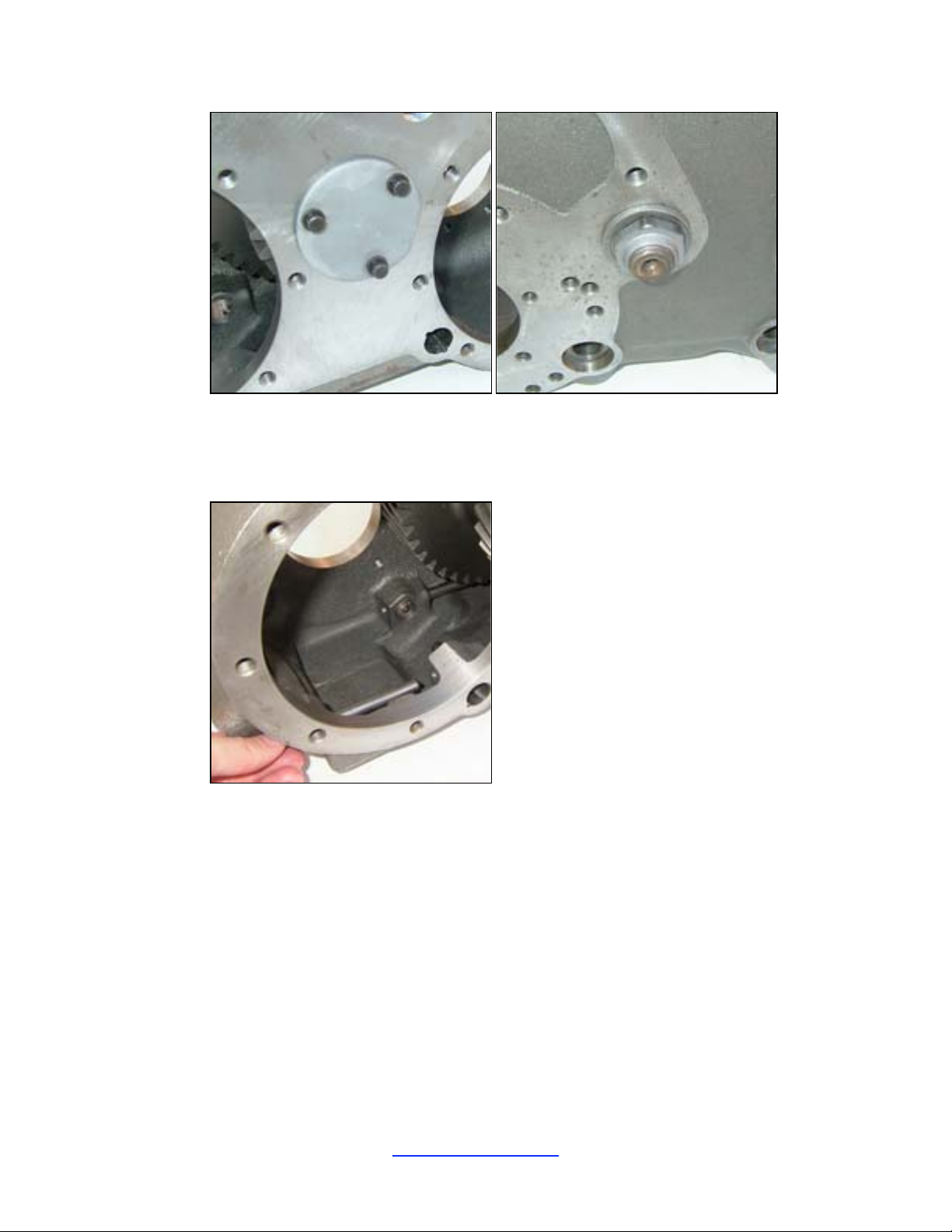
10. Adjust the shim pack (per the measurements taken in step 10) to remove the end play so that the
final setting is 0.000” end play. DO NOT set the shim pack to produce excessive preload on the
tapered roll er bearings. Repeat the above procedures to reinstall the intermediat e gear.
11. Insert both rail pins into the case (lubricated). Make sure the rail pins can slide easily in the bores.
12. Start the long shift rail into the case from the front with the detent notches facing upward.
Position the fork in the case so that the rail can pass through i t. Notice the fork is positioned with
the offset facing inward (see photo in step 15 for view). Push the rail to the neutral (center detent)
position.
13. Install the input bearing into the front of the cas e.
JB Conversions, Inc. Page 8
337-625-2379
337-626-8365 fax www.jbconversions.com
Page 10
LoMax™ 205 – Case and 3:1 Gear Set
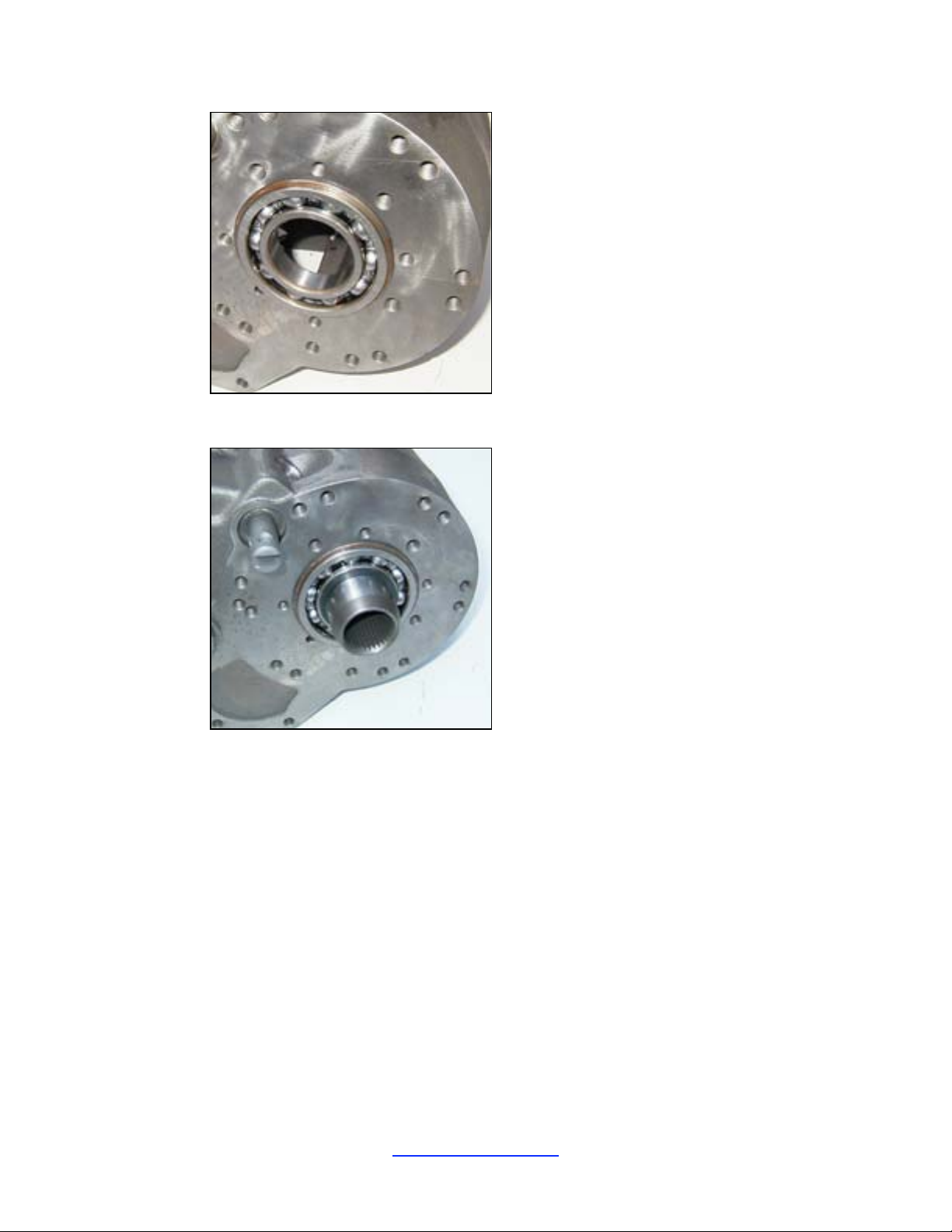
14. Install the input gear from the back of the case and secure it with the snap ring.
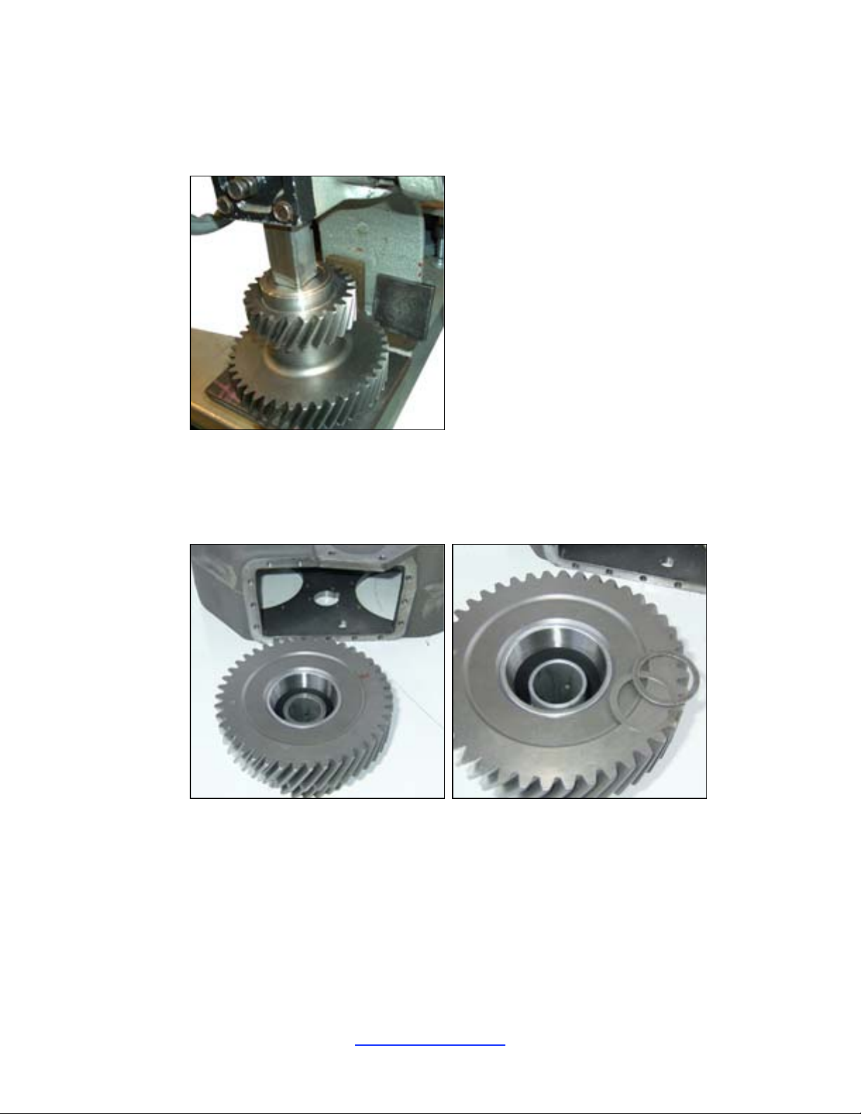
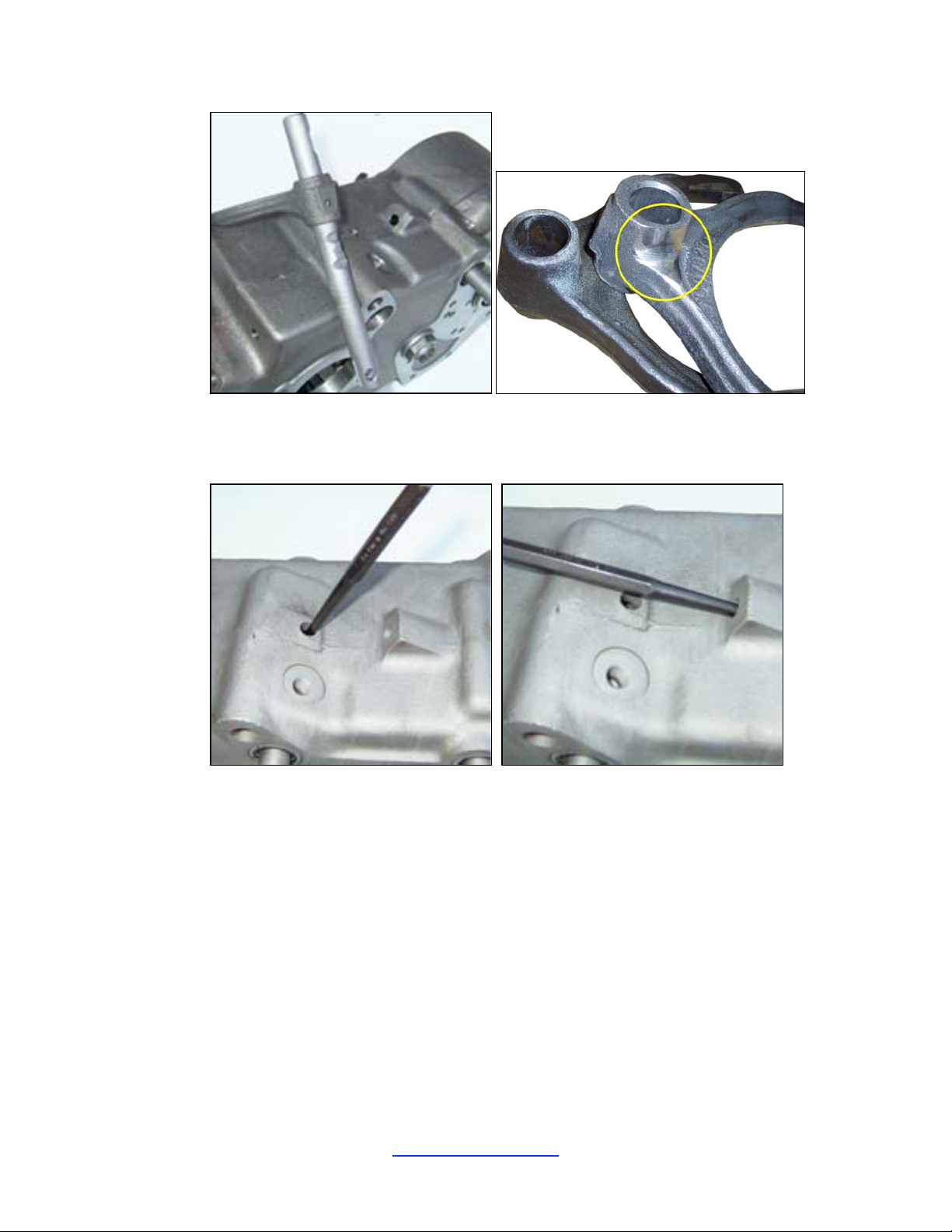
15. Start the short shift rail into the case from the front with the detent notches facing upward.
Position the fork in the case so that the rail can pass through i t. Notice the fork is positioned with
the offset facing inward. Place the rail in the neutral position. NOTE: Minimal grinding is
required on the fork as shown in yellow in the photo on the right.
JB Conversions, Inc. Page 9
337-625-2379
337-626-8365 fax www.jbconversions.com
Page 11
LoMax™ 205 – Case and 3:1 Gear Set
16. Using a punch, install the roll pins into the shift forks securing them to the rails. Visually check
the alignment of the fork a nd rail holes before driving in the roll pins. Tip: it may be easier to start
the roll pin in to th e fork bef o r e tr y in g to install th e fork in the case.
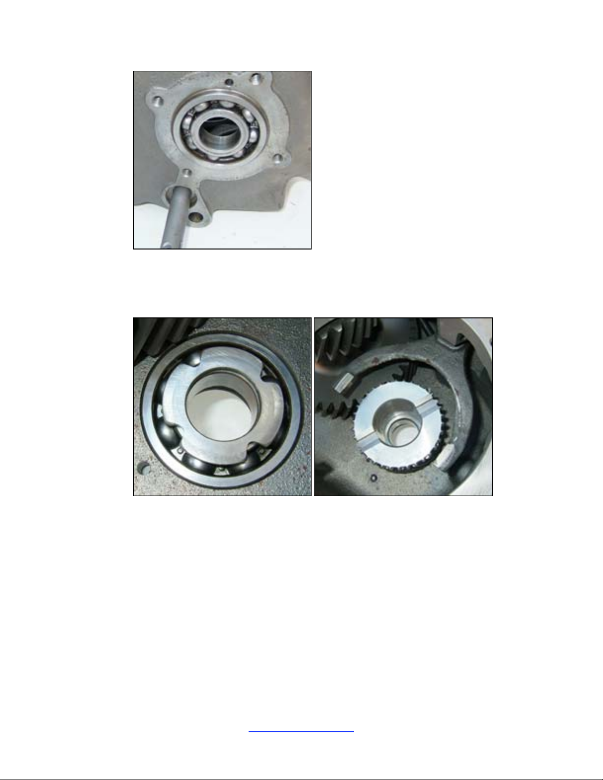
17. Install t he front output shaft bearing into the case includi ng the snap ring on the bearing. Instal l the
aluminum bearing retainer onto the bearing to hold it in place. Do not RTV on this retainer yet.
JB Conversions, Inc. Page 10
337-625-2379
337-626-8365 fax www.jbconversions.com
Page 12
LoMax™ 205 – Case and 3:1 Gear Set
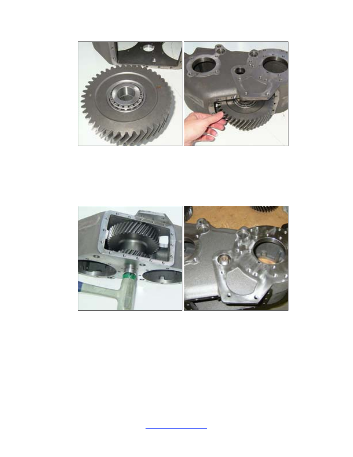
18. Support the case on t he bench with the front face down. Place the thrust washer onto the top of the
bearing (in s ide the case ). NOTE: Apply oil to both sides of the thrust washer.
19. Place the new LoMax gear onto the bearing with the clutch teeth facing upward. NOTE: Apply oil
to the inside of the gear and to both faces.
20. Place the slide ring onto the gear in the case (within the shift fork).
JB Conversions, Inc. Page 11
337-625-2379
337-626-8365 fax www.jbconversions.com
Page 13
LoMax™ 205 – Case and 3:1 Gear Set
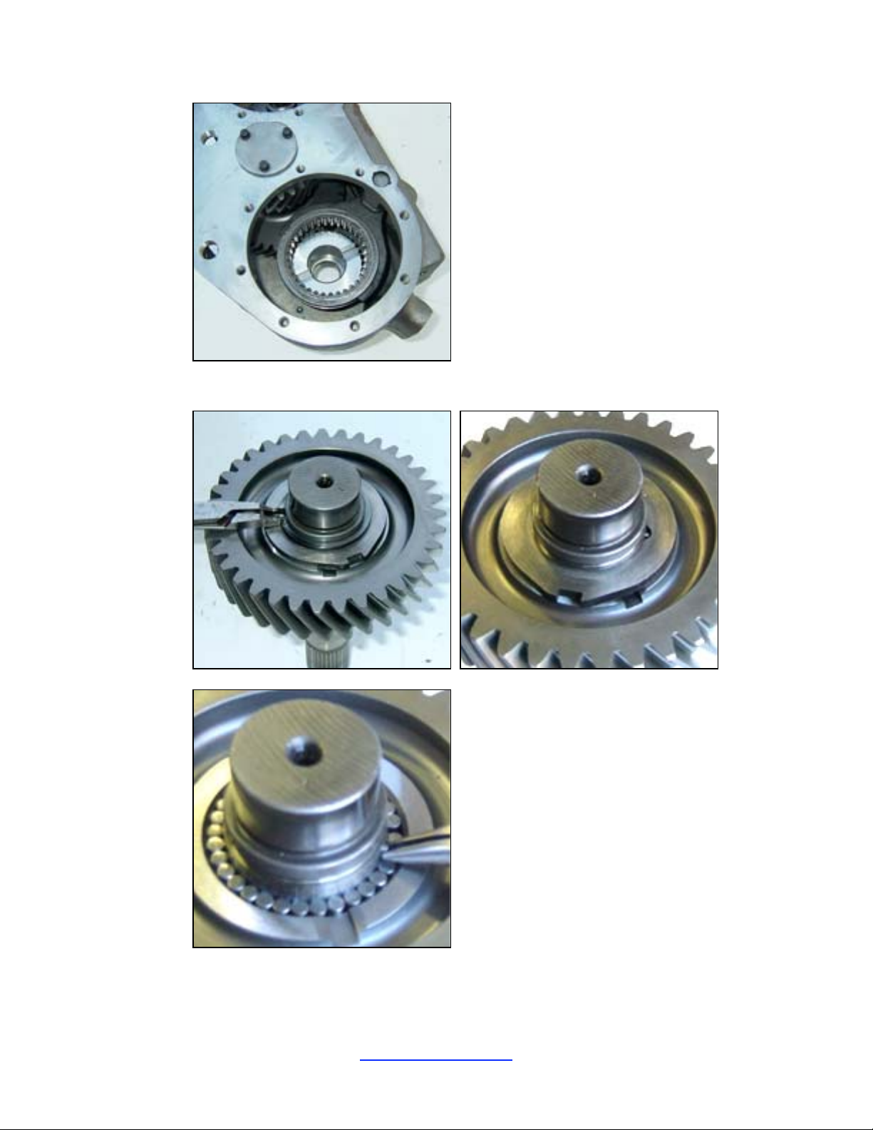
21. Remove the snap ring, thrus t plate, and dowel pin from the original front output shaft.
22. Then remove the original gear from the shaft. The needle bearings may fall off of the shaft as you
lift the g ear .
JB Conversions, Inc. Page 12
337-625-2379
337-626-8365 fax www.jbconversions.com
Page 14
LoMax™ 205 – Case and 3:1 Gear Set
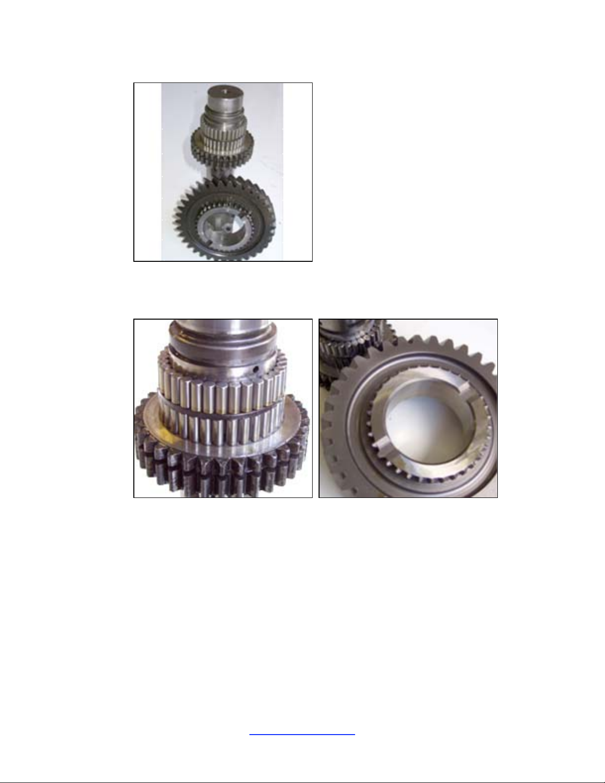
23. Install t he needle bearings onto the front output shaft using grease to hold them in place. Notice
there are two rows of bearings with a spacer in between the two rows. Wipe the bore of the ne w
LoMax gear with gear oil and slide it onto the front output shaft.
24. Install t he small pin into the front output shaft.
JB Conversions, Inc. Page 13
337-625-2379
337-626-8365 fax www.jbconversions.com
Page 15
LoMax™ 205 – Case and 3:1 Gear Set
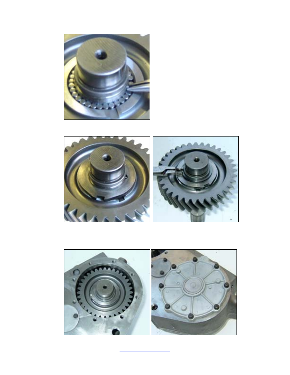
25. Install t he thrust plate onto the shaft followed by the snap ring.
26. Lubricate the shaft with gear oil and Lower the front output shaft assembly into the case. The
shaft should pass through the slide ring, gear, thrust washer, and bea ring installed in steps 18-20.
Apply RTV to the bearing retainer and bolt it to the case (20-40 ft-lb.). Use gaskets if you wish.
JB Conversions, Inc. Page 14
337-625-2379
337-626-8365 fax www.jbconversions.com
Page 16
LoMax™ 205 – Case and 3:1 Gear Set
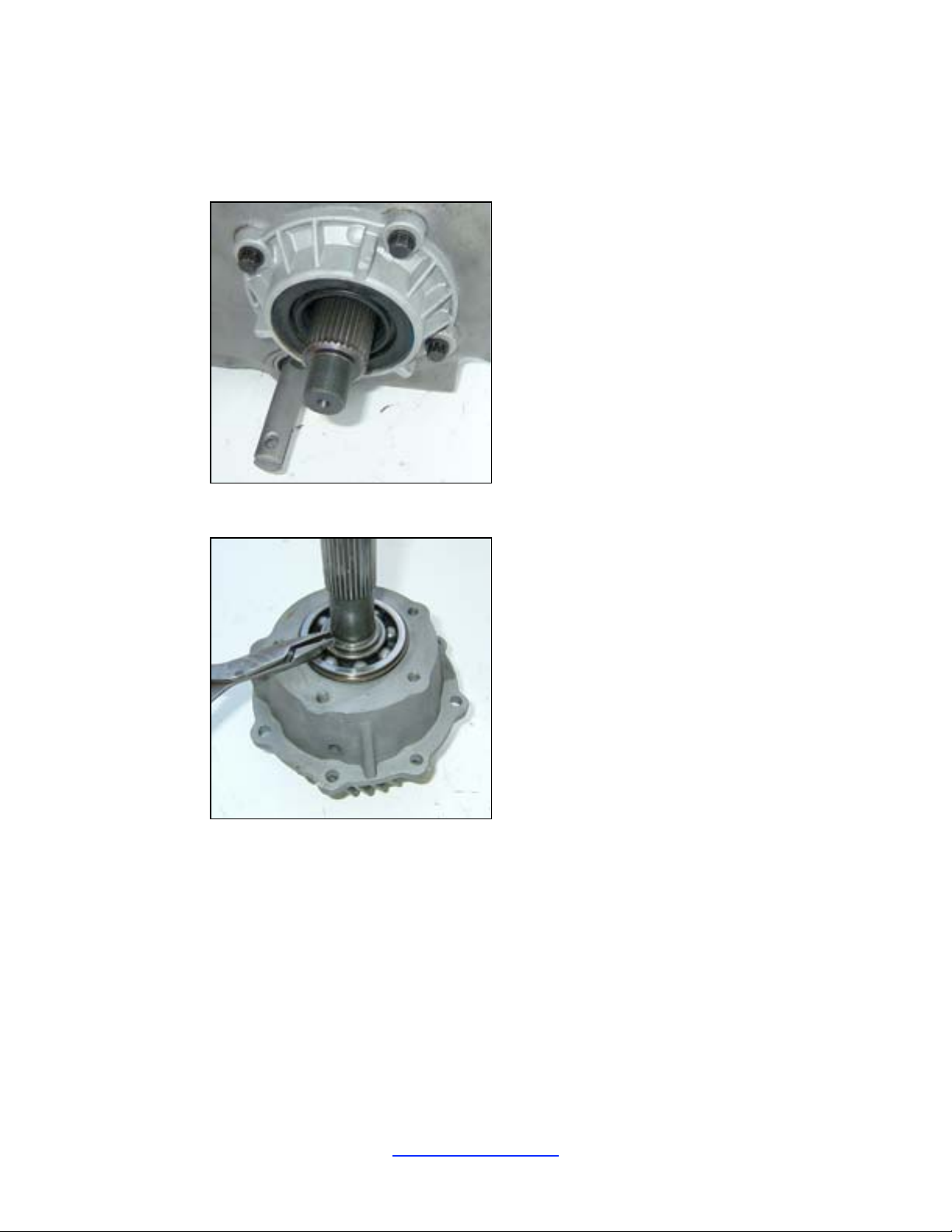
27. Remove the front retainer temporarily inst alled previousl y, appl y RTV, and reinstall. Torque bolts
to 20-40 ft-lb.. Next install the rubber star washer over the threaded end of the shaft followed by
the end yoke or flange. The flange/yoke nut should be torqued to 190 ft-lbs..
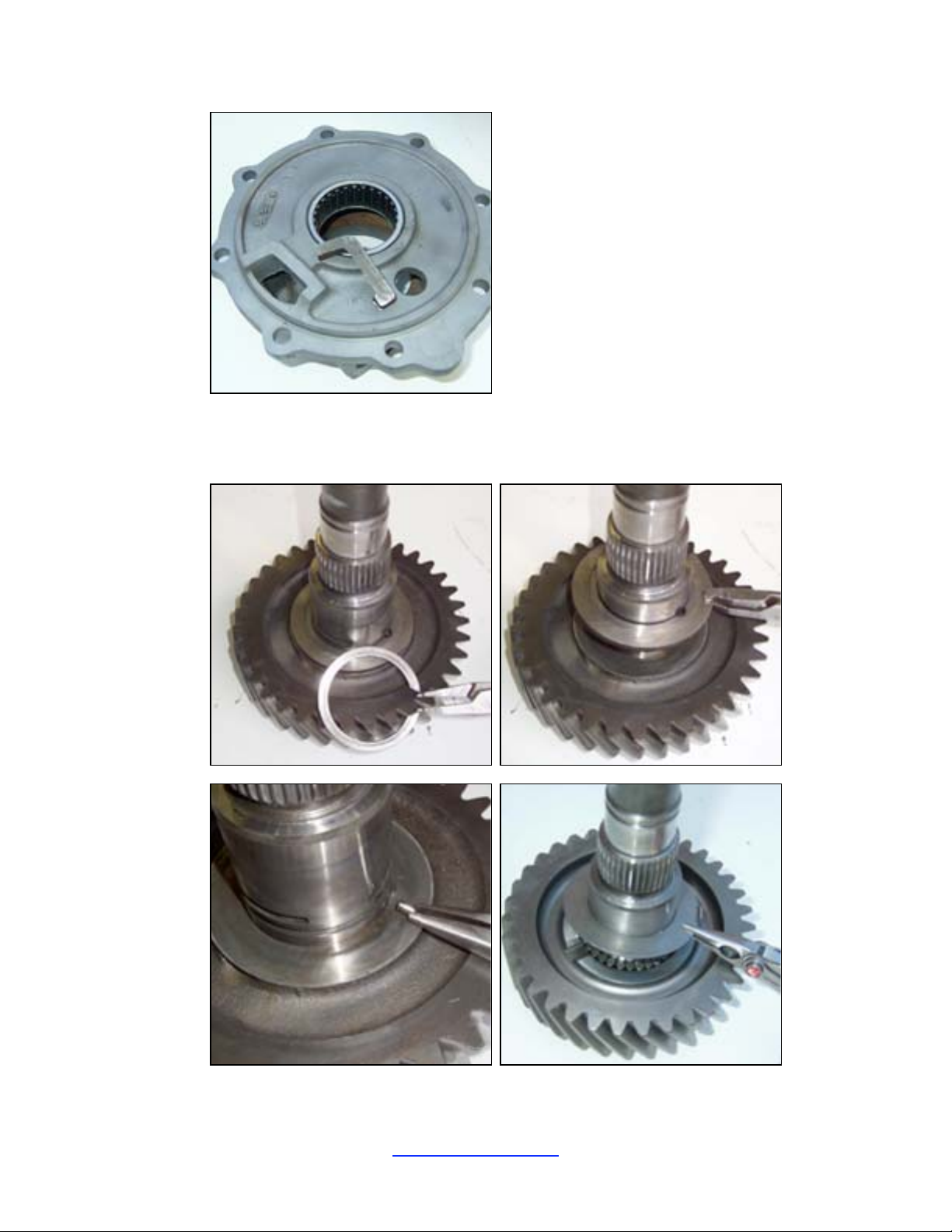
28. Remove the output sha ft snap ring and slide the steel bea r ing housing up and off of the shaft.
29. When you lift up the housing, the needle bearings will fall out.
30. Remove the ball bearing from the top of the bearing housing.
31. Trim the oil vane with a gri nder or saw. Remove 1/4” of material.
JB Conversions, Inc. Page 15
337-625-2379
337-626-8365 fax www.jbconversions.com
Page 17
LoMax™ 205 – Case and 3:1 Gear Set
32. Use grease to reinstall the needle bearings into the housing.
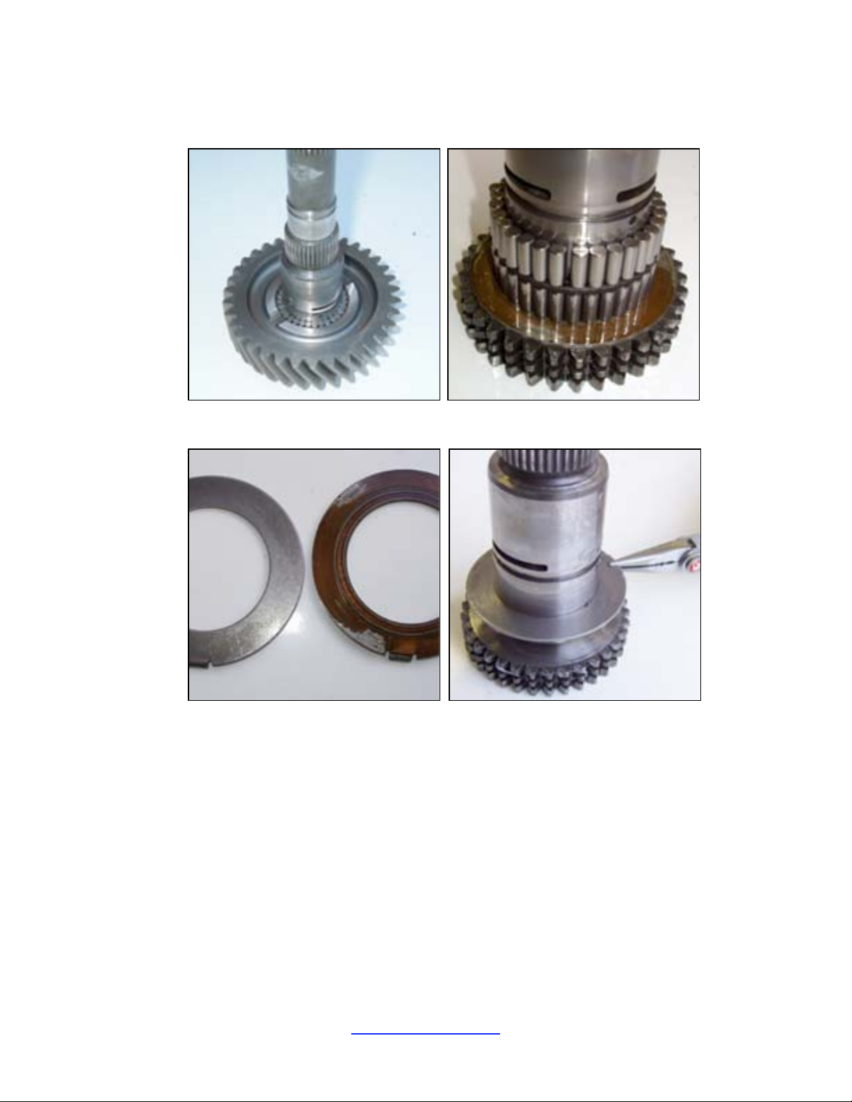
33. Remove the snap ring, thrus t plate, dowel pin, and thrust wa sher from the original rear output
shaft.
JB Conversions, Inc. Page 16
337-625-2379
337-626-8365 fax www.jbconversions.com
Page 18
LoMax™ 205 – Case and 3:1 Gear Set
34. Remove the origi nal ge ar from the shaft. The needle beari ngs may fal l off of the shaft as you lift
the gear.
35. Inspect the lower thrust washer and replace if necessary.
36. Install t he needle bearings onto the rear output shaft (above the thrust washer) using grease to hold
them in place. Notice there are two rows of bearings with a spacer in between the two rows. Wipe
the bore of the new LoMax gear with gear oil and slide it onto the front output shaft.
JB Conversions, Inc. Page 17
337-625-2379
337-626-8365 fax www.jbconversions.com
Page 19
LoMax™ 205 – Case and 3:1 Gear Set
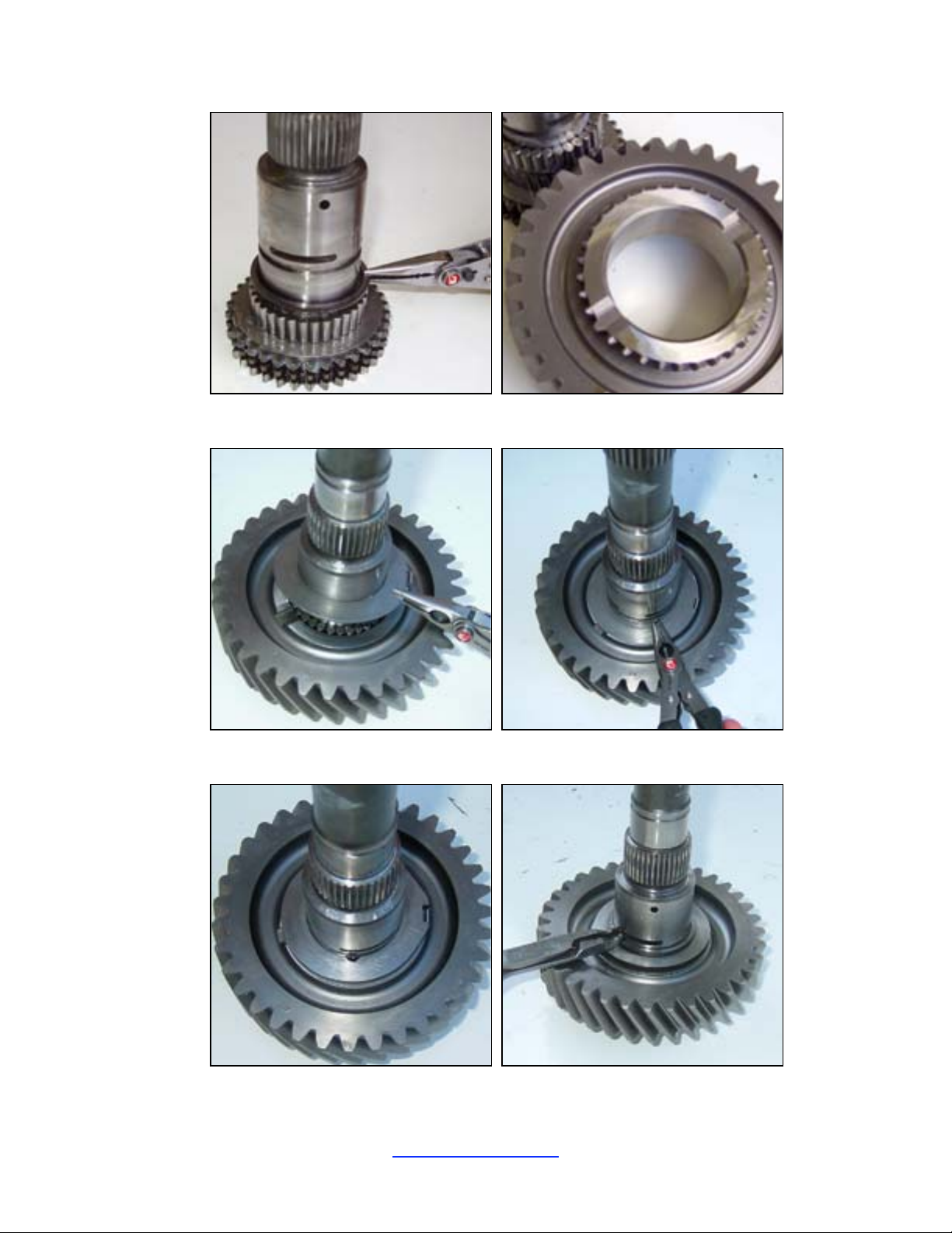
37. Install the uppe r thrust washer and dowel pin.
38. Install the thrust plate followed by the snap ring.
JB Conversions, Inc. Page 18
337-625-2379
337-626-8365 fax www.jbconversions.com
Page 20
LoMax™ 205 – Case and 3:1 Gear Set
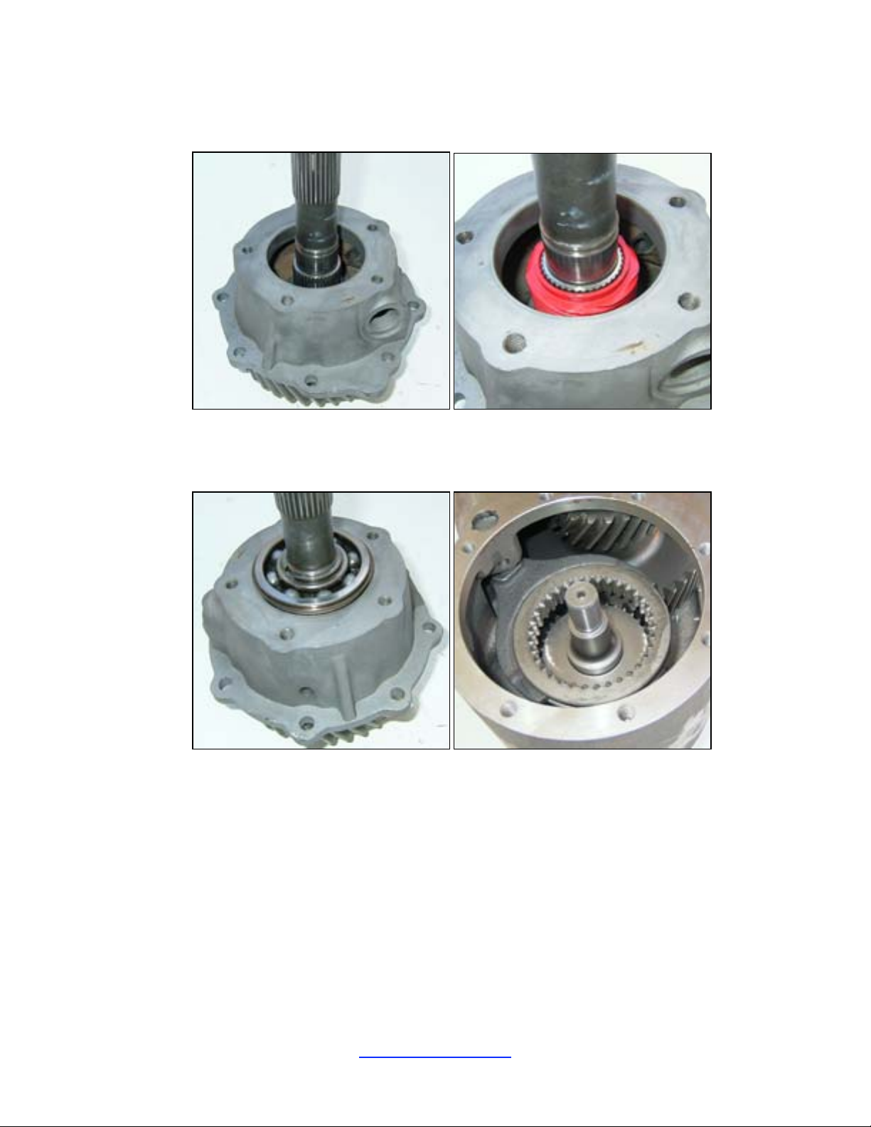
39. Lower the steel bea r ing housing onto the output shaft. Install the plas tic speedometer gear onto the
shaft.
40. Tap the ball bearing into the steel housing followed by the snap ring.
41. Align the slider ring into the shift fork. The slider ring must fit into the clutch teeth on the back of
the input gear.
42. Install t he needle bearings into t he rear output shaft. Be sure the spacer and retaining ring are
above the needle bearings. Use grease to hold the needle bearings into pla ce.
JB Conversions, Inc. Page 19
337-625-2379
337-626-8365 fax www.jbconversions.com
Page 21
LoMax™ 205 – Case and 3:1 Gear Set
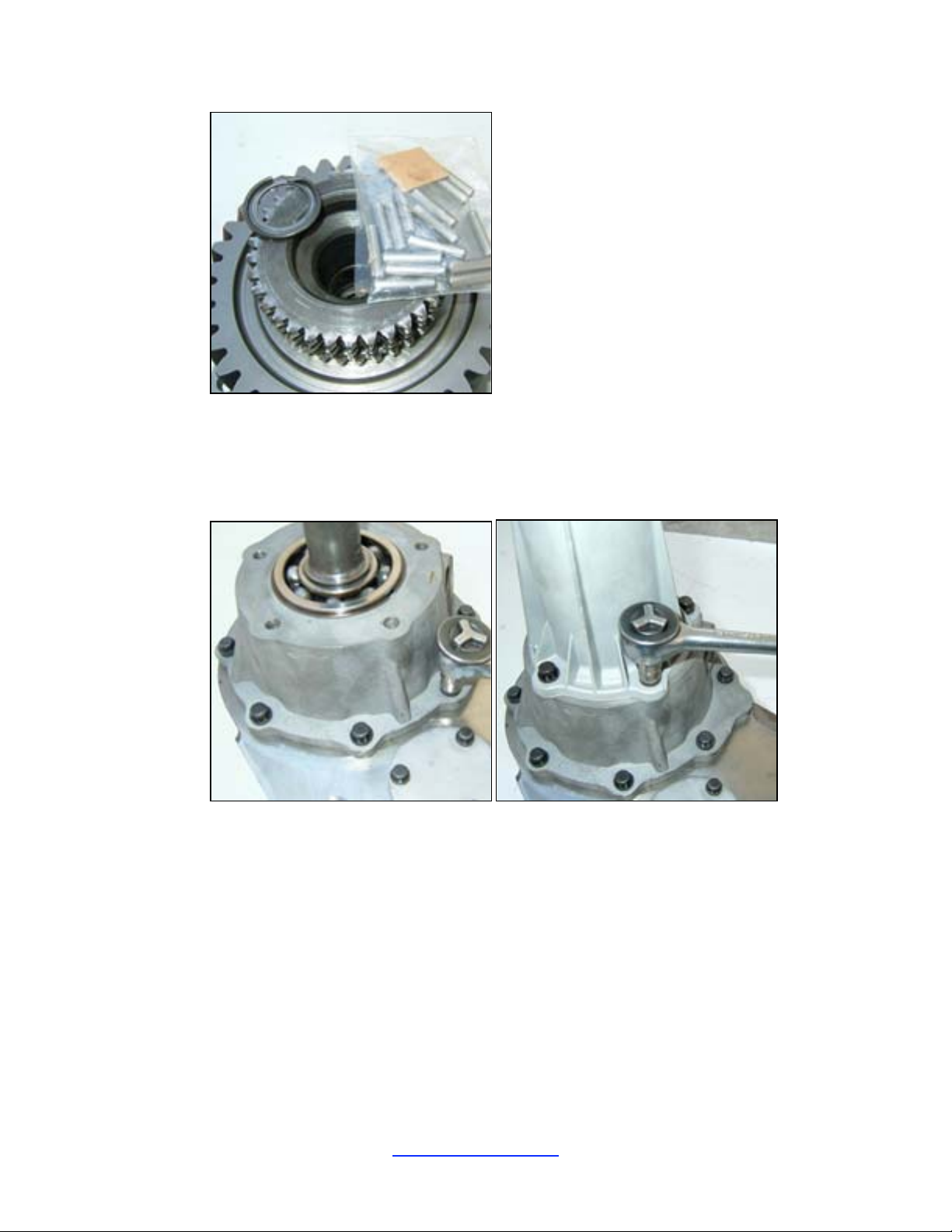
43. Apply RTV to the mounti ng face of the stee l bearing housing. Use a gasket if you wish.
44. Lower the output shaf t assembly onto the case. Make sure the clutch teeth on the out put gear
engage with the slide ring internal teeth.
45. Bolt the steel housi ng to the new case (20-40 ft-lb.).
46. Bolt the tail housing onto the rear bearing hous ing (20-40 ft-lb.).
47. Install t he poppet balls, springs, and threaded caps.
JB Conversions, Inc. Page 20
337-625-2379
337-626-8365 fax www.jbconversions.com
Page 22
LoMax™ 205 – Case and 3:1 Gear Set
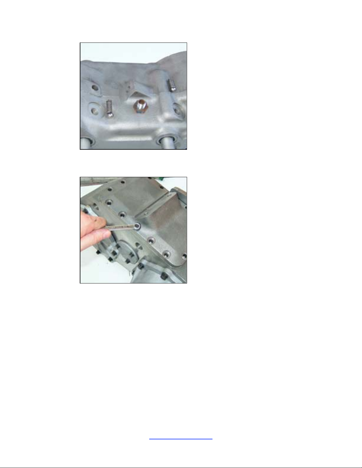
48. Install hol e plugs into the two side holes a nd 2 top holes. NOTE: Install the drain and fill plugs.
49. Apply RTV to the mounting surface of the i ns pect ion cover and install (15-25 ft-lbs ).
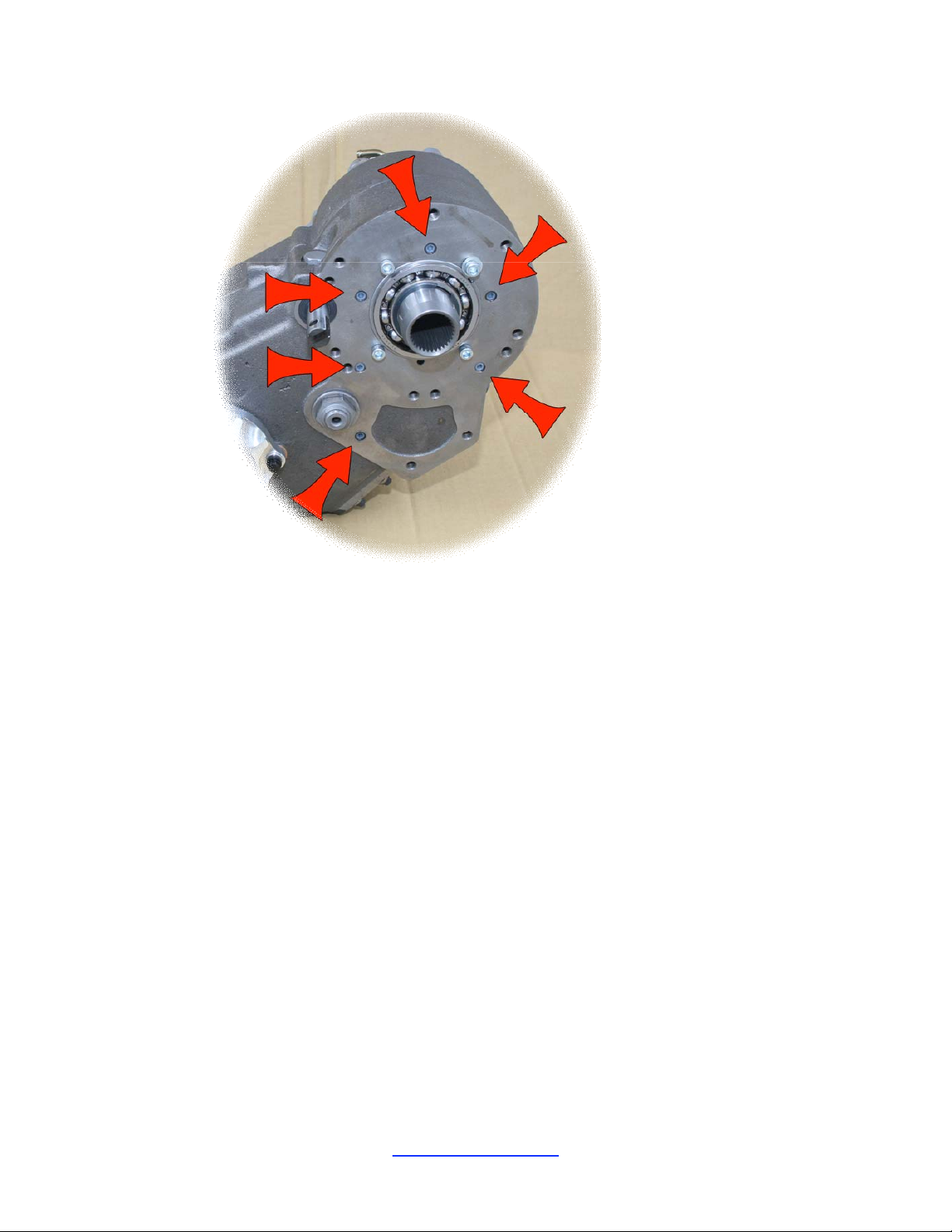
50. Depending on tra nsmission applicati on, some of the bolt holes on the front of the LoMax case may
not be used. Several of the t hrea ded holes on the front of the LoMax case are “thru” drilled.
Unused, thru-drilled holes should be plugged with the nylon inserts supplied in the kit. Use RTV
on the threads of each plug before installing them into the new case. Failure to complete this step
will result in fluid loss. See photo for example. Your app lication may vary.
JB Conversions, Inc. Page 21
337-625-2379
337-626-8365 fax www.jbconversions.com
Page 23
LoMax™ 205 – Case and 3:1 Gear Set
NOTE: The 4 allen head bolts in the photo above are inst alled for shippi ng only. Remove prior
to installation if present.
JB Conversions, Inc. Page 22
337-625-2379
337-626-8365 fax www.jbconversions.com
 Loading...