

Page 1

D
D
a
n
a
3
0
0
32 Spline Rear Output Shaft Upgrade
Manufactured by JB CONVERSIONS, INC.
Part No. 2308
Instruction Rev: 2009.09.26
Kit Components
. Aluminum bearing housing
. 32 spline rear output shaft
. Aluminum seal retainer
. National oil seal #473239
. (6) Allen cap screws 5/16" x .75"
. (5) Allen cap screws 3/8" x 1.25"
. CV yoke # 2-4-5341
. 7/8" x 20 Lock nut - Chrysler #4167924
. 7/8" x 20 Shim Setup nut
. Rubber star washer seal - Chrysler #4210973
. Speedometer gear - Chrysler #4338996
. Snap ring - Chrysler #4338997
. Large Spacer ring
. Small Spacer ring
. Needle bearing
. Tapered roller bearing #30207 (cup & cone)
. Tapered roller bearing #26822, #26885 (cup & cone)
. Shim set
. Vent fitting 1/8" NPT x 5/16"
IMPORTANT!
a
Installation Instructions
n
Phone: 337-625-2379
a
3
0
0
Properly secure the vehicle and remove the Dana 300 from the chassis. Drain the
Dana 300 of all oil. The reassembly portion of these instructions illustrates a Dana
300 cut-a-way model. Various components of this display model are removed for
other purposes. The steps for reassembly coincide with the photos therefore you
should not be concerned that your unit is not in a state of disassembly as seen in the
cut-a-way case.
1
Page 2
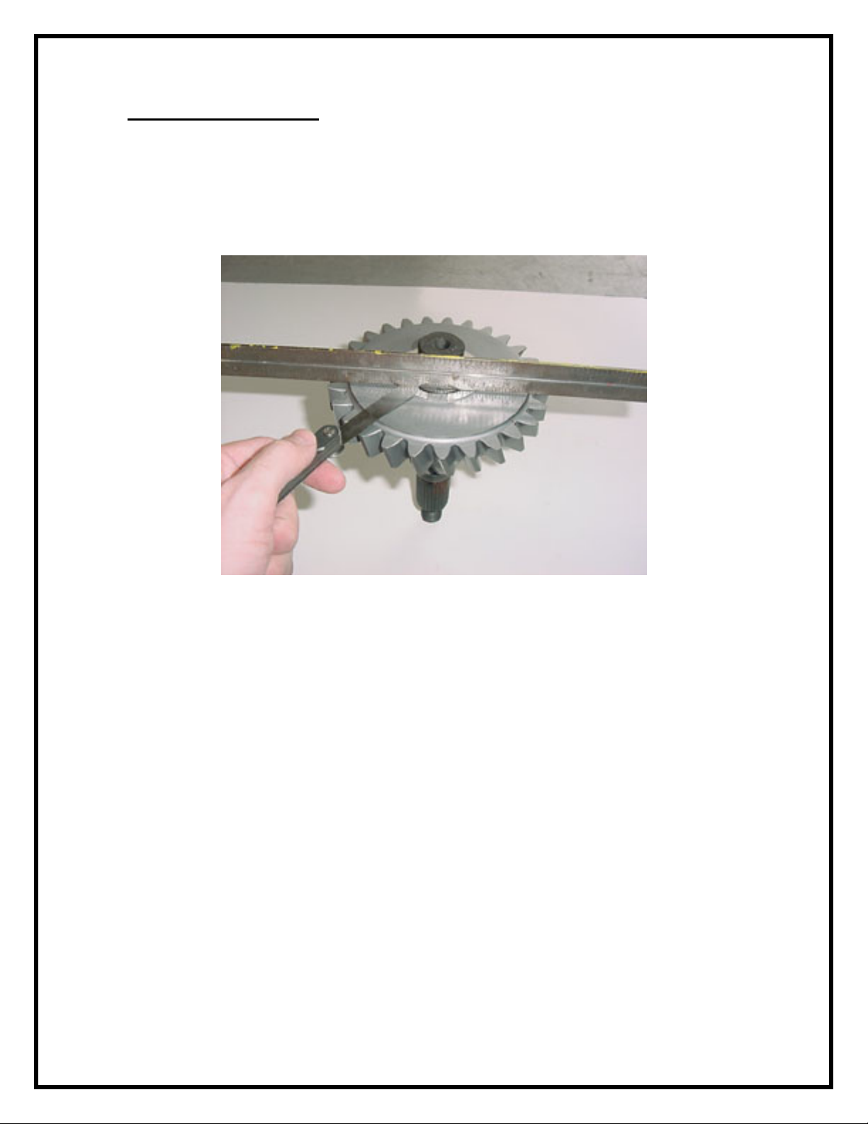
PREASSEMBLY CHECK
Once the stock helical gear has been removed from the case, place the stock gear
onto the new rear output shaft. Place a straightedge across the shoulder of the new
shaft as shown (Fig.1). Verify clearance between the straightedge and the grinded
surface of the gear. The gear shoulder on the shaft SHOULD NOT be any higher
than the two grinded gear surfaces.
FIG: 1
2
Page 3
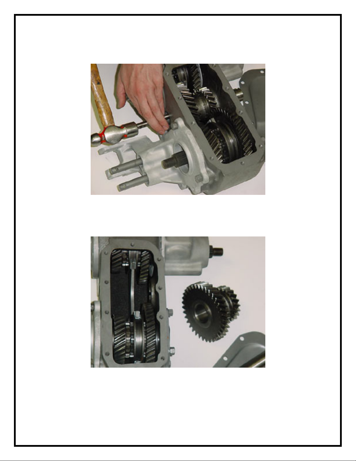
1) Remove the metal lock tab and corresponding intermediate shaft using a
flat brass or wood punch (Fig.2).
FIG: 2
2) Roll the intermediate gear up and out of the case. Be careful to retain the
needle bearings and three spacer rings in the intermediate gear bore (Fig.3).
FIG: 3
3
Page 4
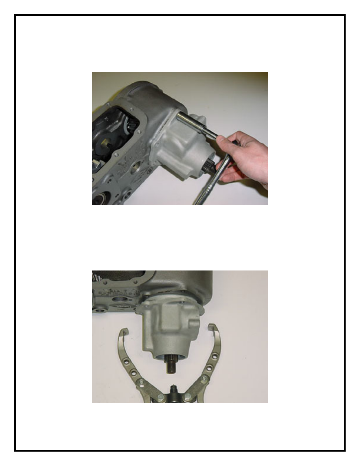
3) Remove the rear output yoke nut and end yoke. Remove the 5 bolts
holding the rear bearing housing to the case (Fig.4). New bolts are supplied
in the kit.
FIG: 4
4) Using a bearing puller, remove the aluminum housing from the case
(Fig.5). The rear outer tapered roller bearing will slide off of the shaft as the
housing is removed. You do not have to remove the oil seal to perform this
step. If you have the type of puller that is designed to remove tapered roller
bearings, remove the last tapered roller bearing from the output shaft.
FIG: 5
4
Page 5
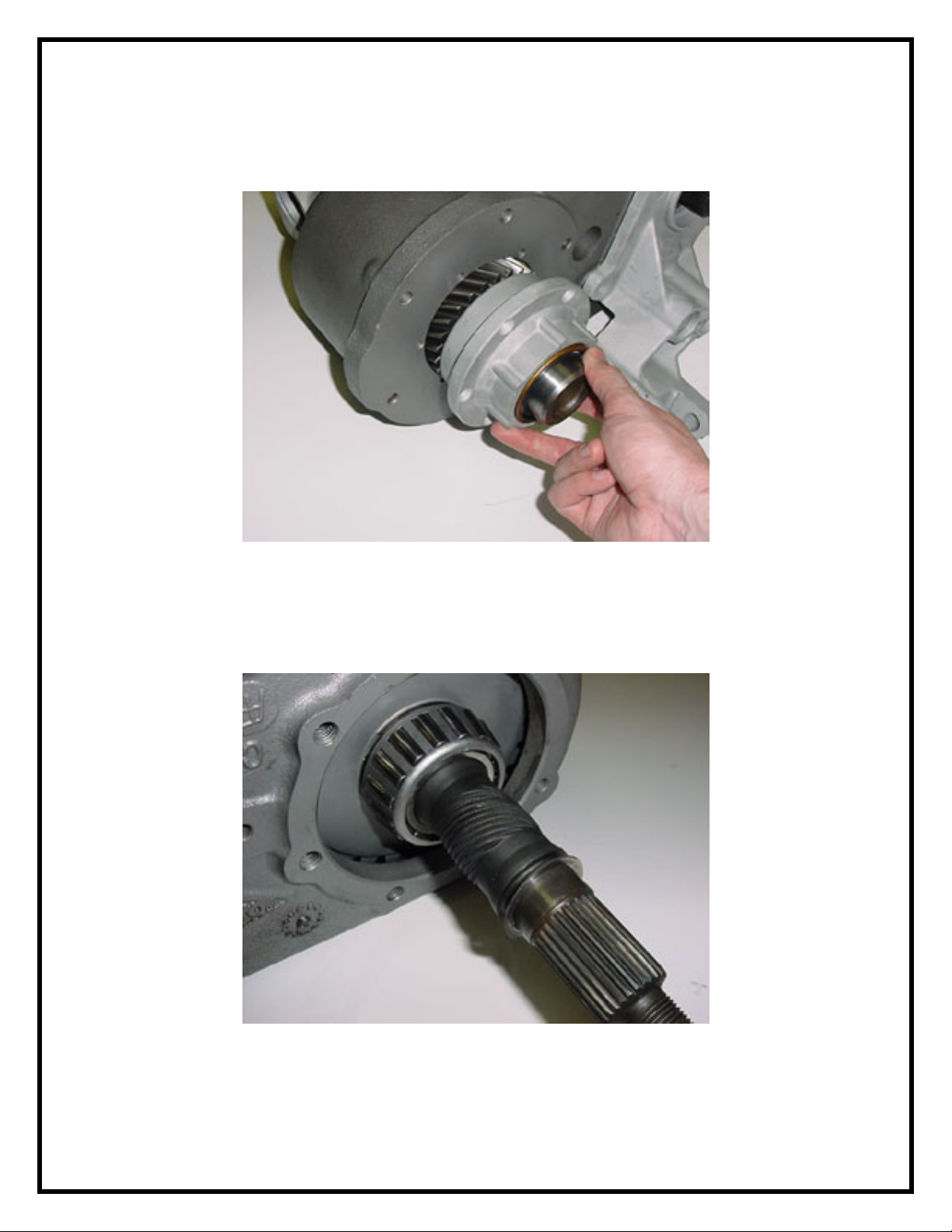
5) Remove the 6 bolts holding the input-bearing retainer housing to the case
(Fig.6). You may need to gently pry the retainer away from the case to
remove it entirely.
FIG: 6
6) If you have removed the second tapered roller bearing in step 4, leave the
gear, slider ring, and shift fork in place as you slide the output shaft out of
the case (Fig.7). Proceed to step #10.
FIG: 7
5
Page 6
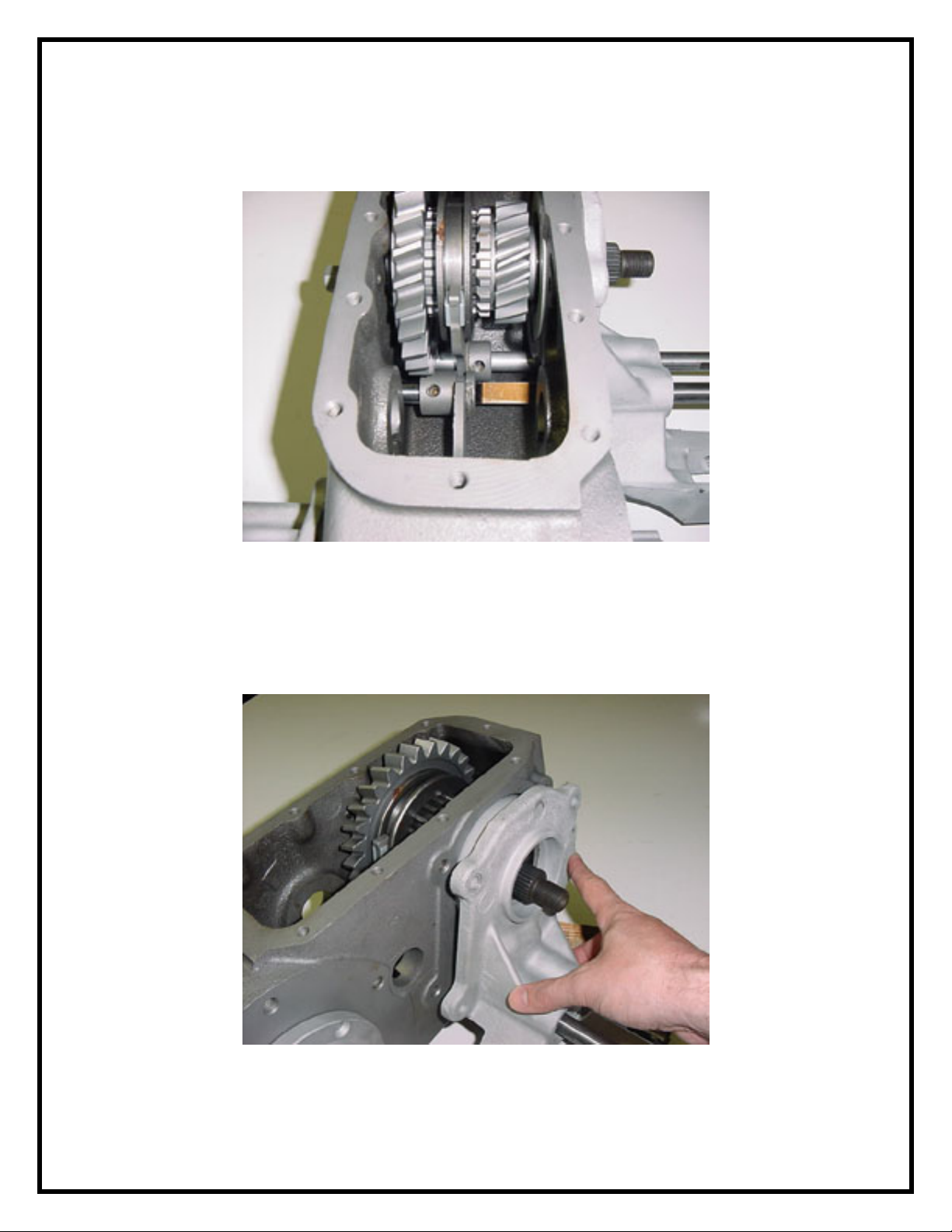
7) If you were not able to remove the second tapered roller bearing in step
4, loosen the shift fork set screws and remove the front output yoke nut and
end yoke (Fig.8).
FIG: 8
8) Remove the bolts holding the aluminum front bearing retainer housing
(shift tower) followed by the housing itself (Fig.9). The rails should slide
through the forks as the housing is removed. After the housing/rails are out,
remove the large shift fork and corresponding slider ring. Proceed to step 9.
FIG: 9
6
Page 7
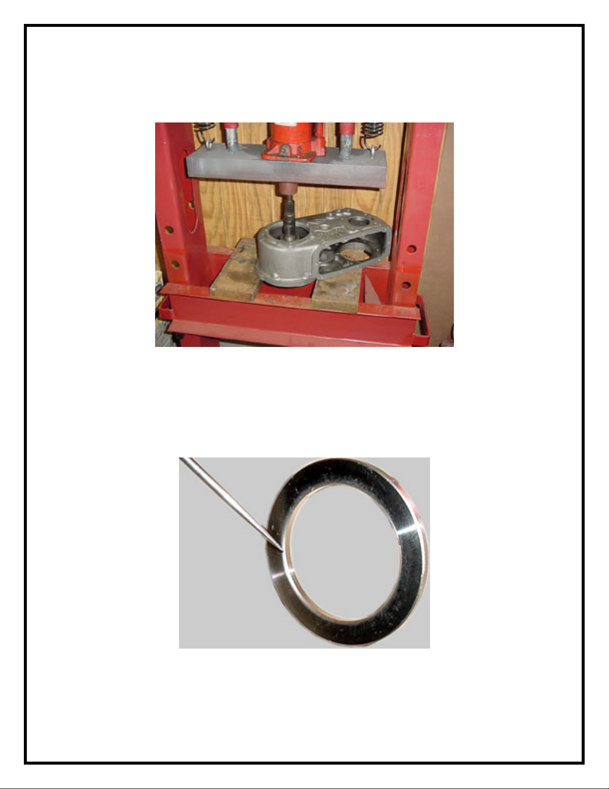
9) Place the case in a press and remove the shaft (Fig.10). The front output
shaft is removed in this photo however it is not necessary for completion of
this kit installation.
FIG: 10
10) From this step forward, an empty, cut-a-way display case is used to
provide better visibility of the components as they are reassembled. Note the
chamfer on the ID edge of the thrust washer (Fig.11a). Only one side of the
thrust washer is machined with the chamfer. This chamfer should face the
shoulder on the shaft.
FIG: 11a
You will notice the lower tapered roller bearing and spacer has been installed
onto the new output shaft (Fig.11b). This has been done to ease your setup
7
Page 8
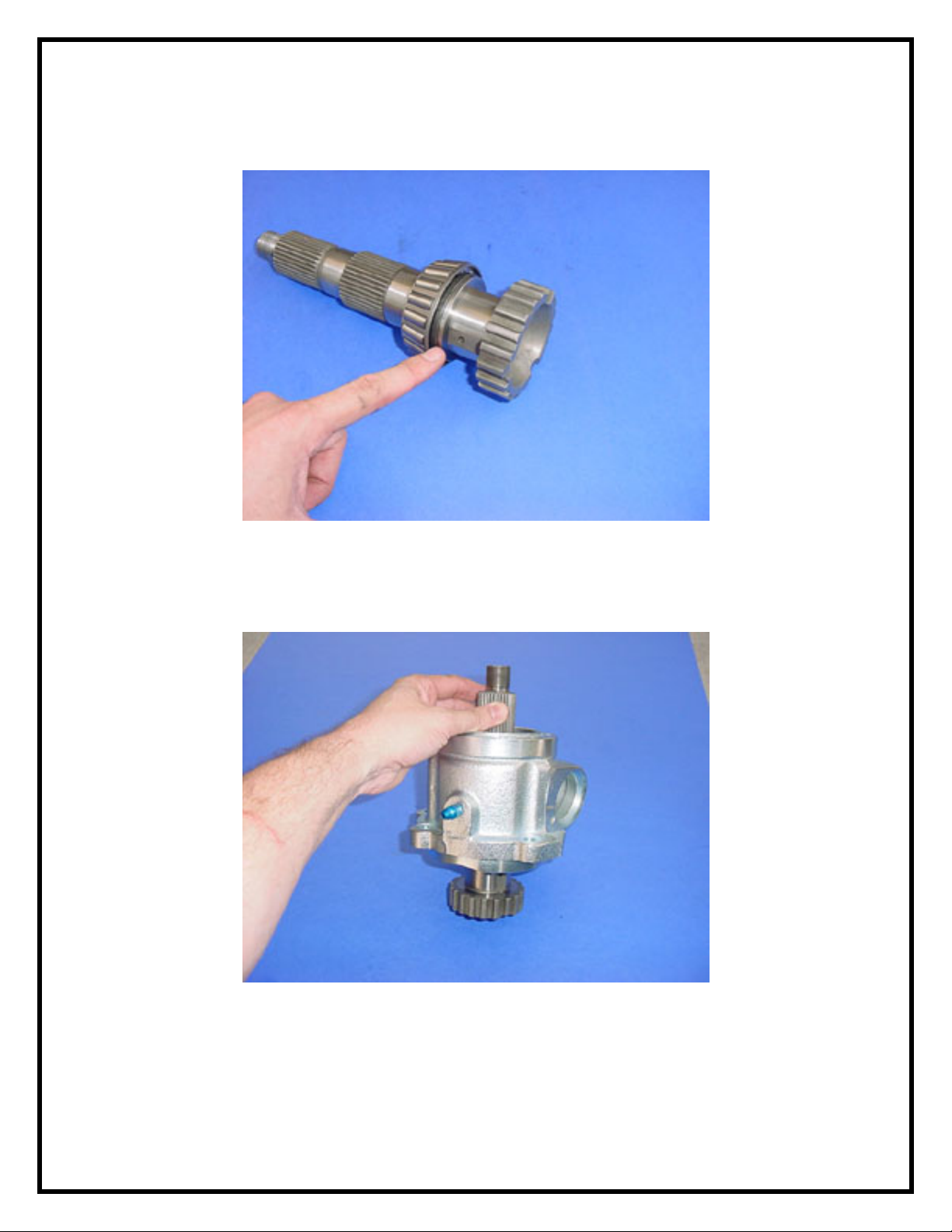
of endplay. You should also verify that the needle bearing is already installed
into the bottom bore of the new shaft.
FIG: 11b
11) Place the new bearing housing onto the shaft so that it comes to rest on
the lower tapered roller bearing (Fig.12).
FIG: 12
8
Page 9
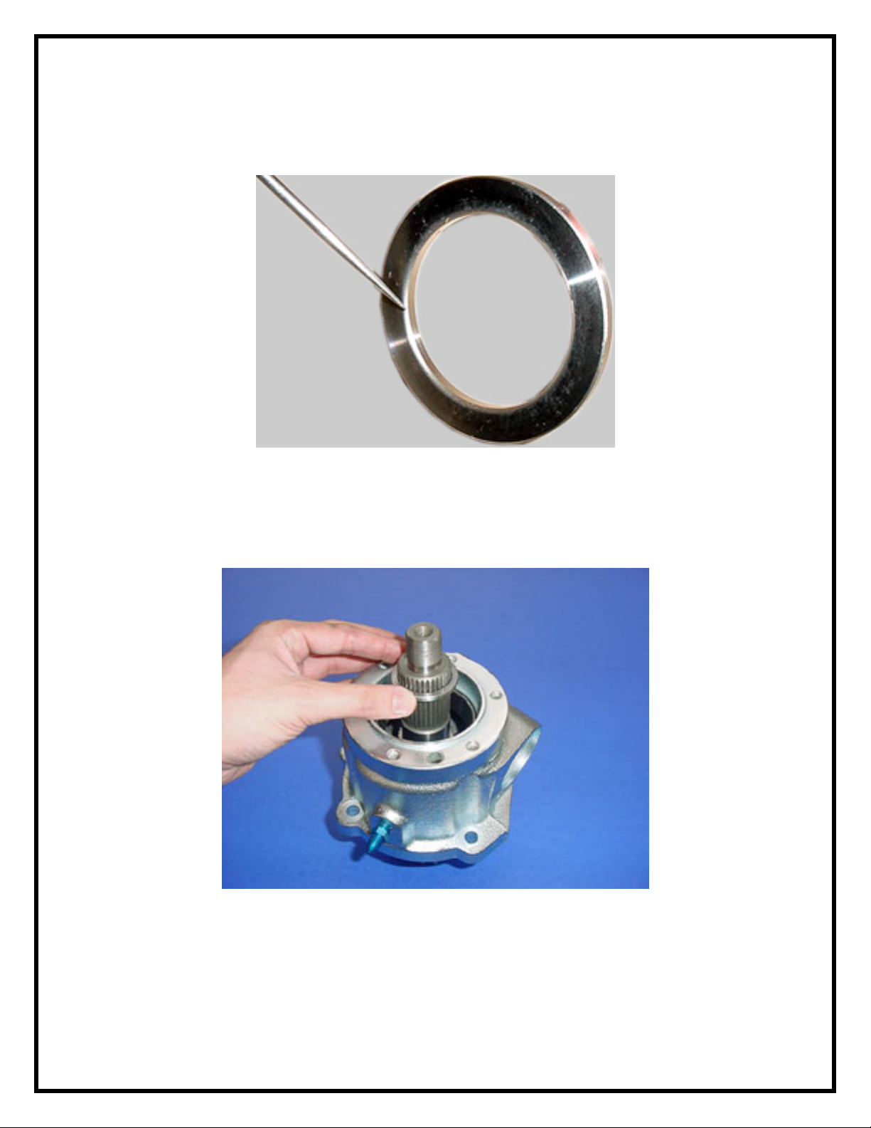
12) Note the chamfer on the ID edge of the thrust washer (Fig.13a). Only
one side of the thrust washer is machined with the chamfer. This chamfer
should face the shoulder on the shaft.
FIG: 13a
Place the thrust washer onto the shaft and lower to the shoulder on the
shaft. The tapered edge on the thrust washer I.D. faces the shaft shoulder
(down) (Fig.13b).
FIG: 13b
13) Place the shims supplied in the kit onto the shaft and slide them down to
rest on top of the thrust washer (Fig.14). Procedures for choosing the correct
combination thickness of shims can be done a number of ways depending
upon personal preference. You can start with no shims and work backwards
9
Page 10
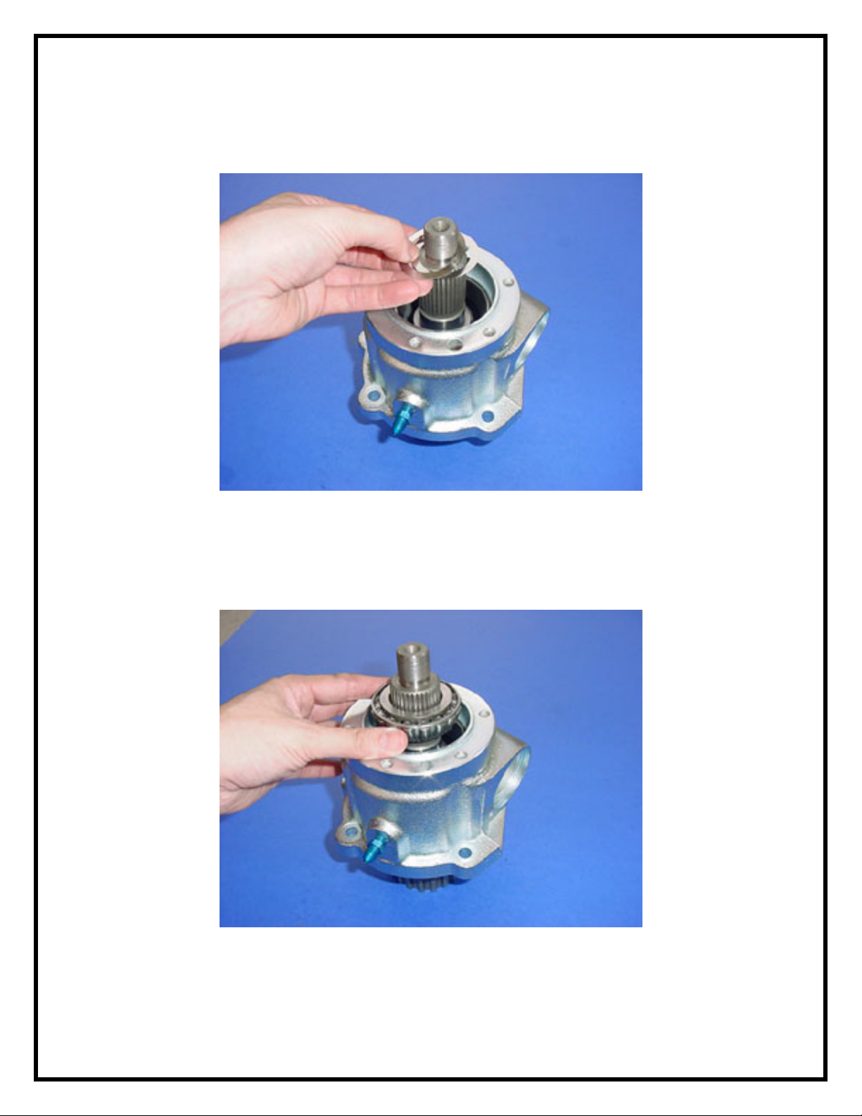
adding shims until proper endplay is achieved (0.000"-0.0015"). The other
method is to install all shims first and then remove them selectively to
achieve the same result.
FIG: 14
14) Depending upon your preferred method of achieving step 10,
install/remove the bearing as needed during the process. This bearing is a
tight "slip-fit" thus allowing step #19 to be performed easily (Fig.15).
FIG: 15
10
Page 11
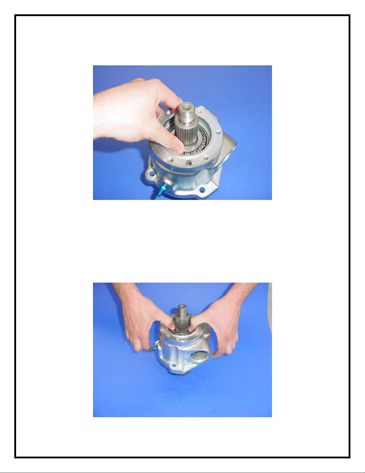
15) Be sure to push the bearing all the way onto the top of the bearing
during shim setup (Fig.16).
FIG: 16
16) End play must be checked for proper bearing preload. Push the bearing
number 30207 onto the shaft as shown (Fig.17). You will need to install the
yoke and "special setup nut" (torque to 180 ft-lbs) before checking
endplay. Use a dial indicator (not shown) to observe 0.000"-0.0015" of end
play. It is easier to perform the endplay adjustments at this time instead of
later in the installation after the remainder of the entire case is being
handled.
11
Page 12
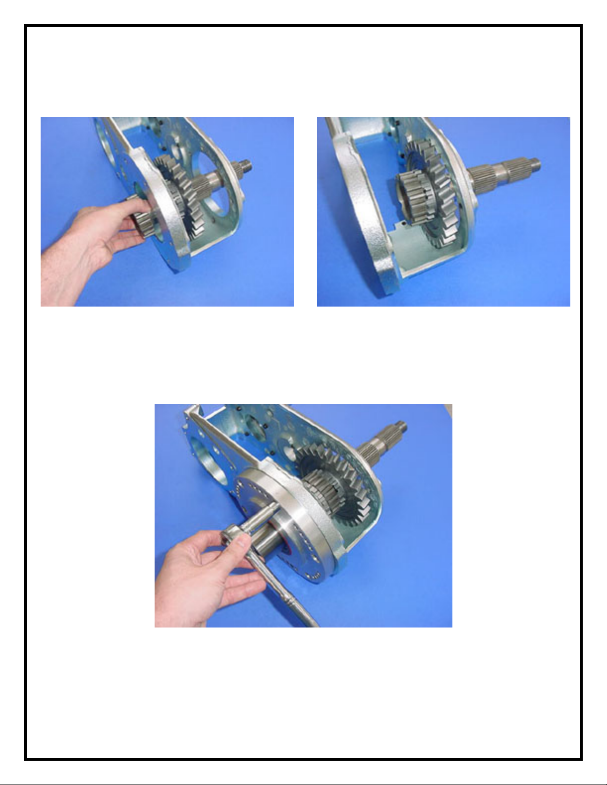
FIG: 17
17) Slide the new output shaft into the stock gear as shown (Fig.18,19).
FIG: 18
18) Install the original input retainer assembly into the case to support the
output shaft for the following steps. For the photo, we are using our billet
rotation ring and LoMax 4:1 gearset however procedures will be identical
using your stock components (Fig.20).
FIG: 19
FIG: 20
12
Page 13
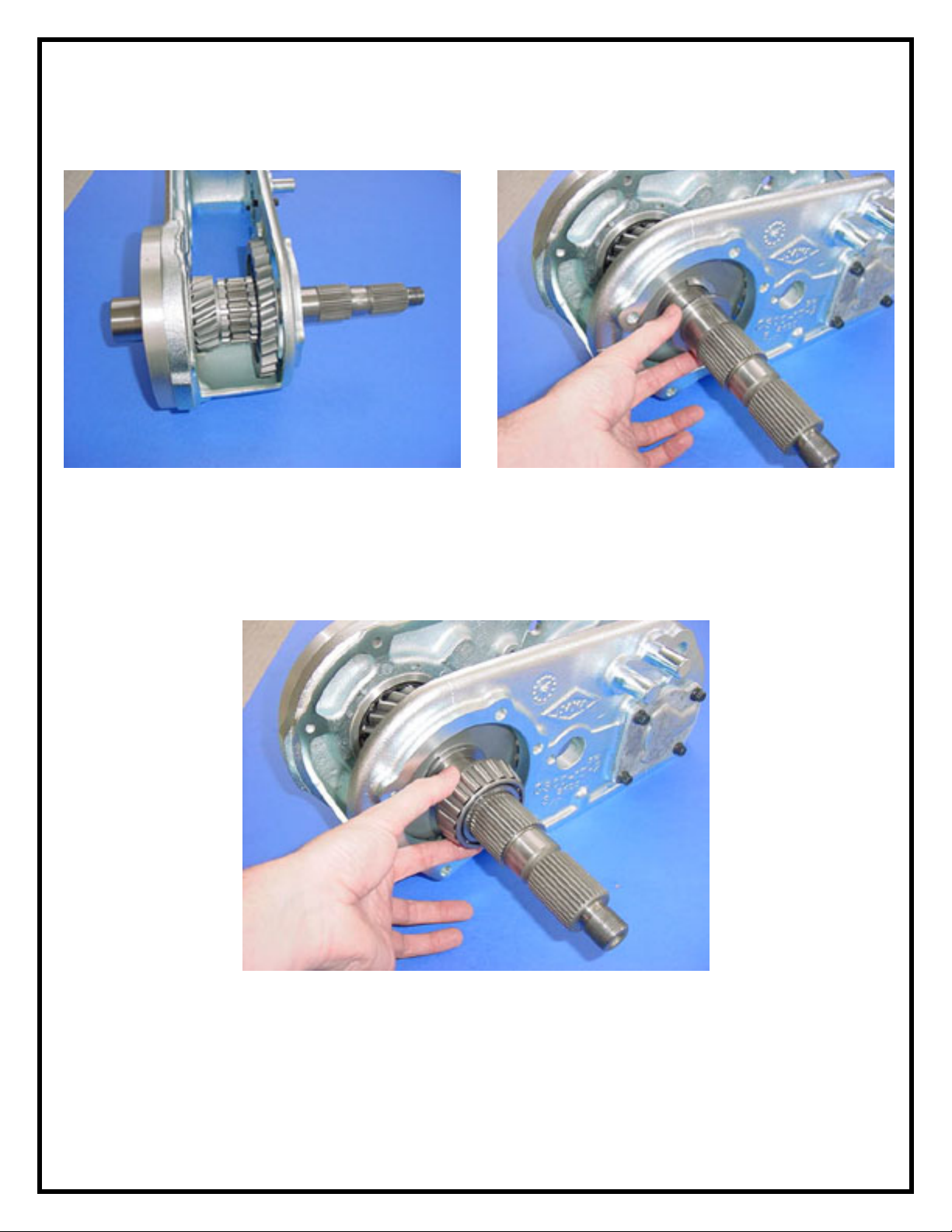
19) With the output shaft supported as shown, slide the larger spacer ring
onto the shaft. The tapered edge on the ring I.D. faces the gear (Fig.21,22).
FIG: 21
20) Slide the new tapered roller bearing onto the shaft as far as possible by
hand (Fig.23). The shaft is sized to provide a VERY light press fit onto the
shaft. You may be able to slide the bearing up to the spacer ring without the
aid of a punch or press. This fit is intentional to aid in your setup.
FIG: 22
FIG: 23
13
Page 14
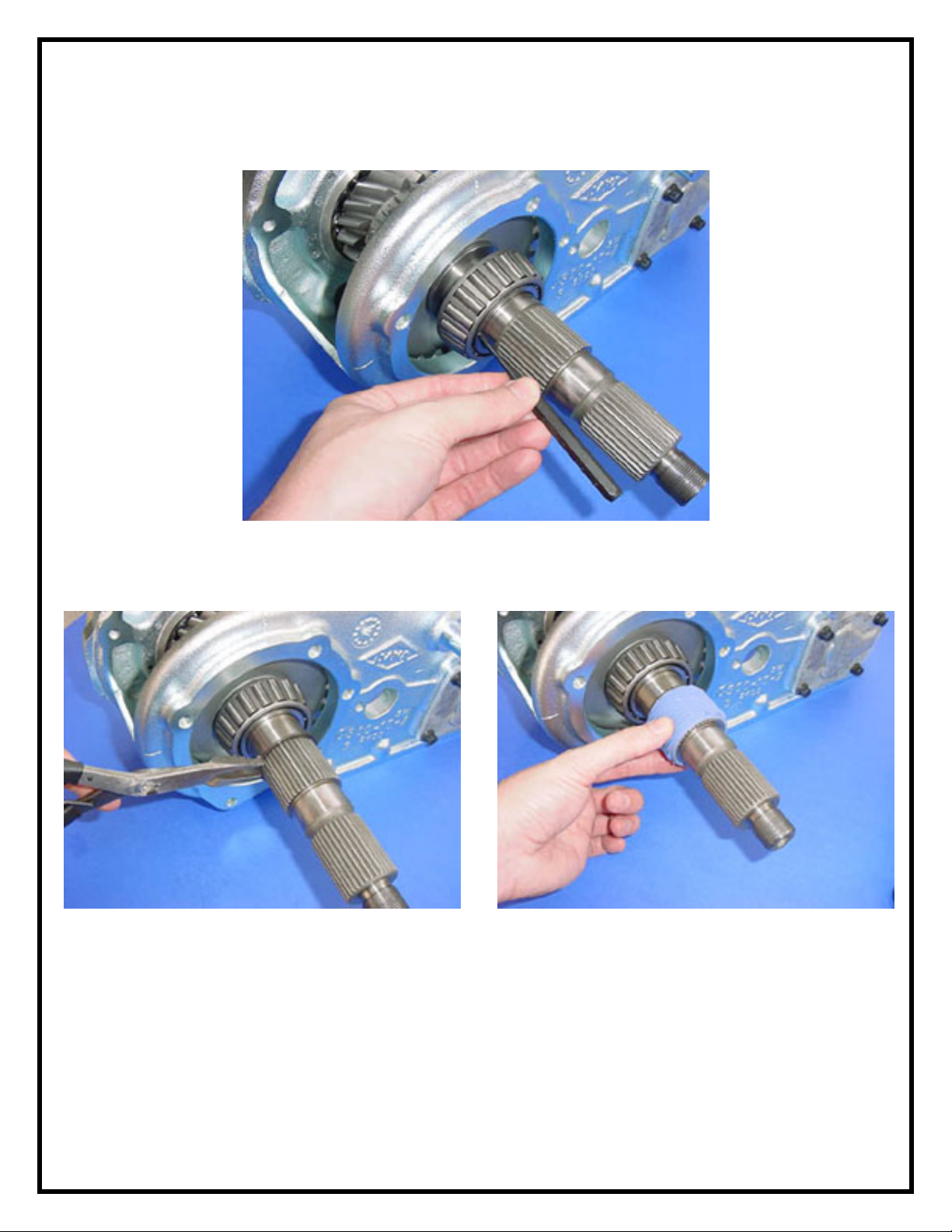
21) If a punch is necessary, use caution and proper technique so that the
bearing is not damaged (Fig.24).
FIG: 24
22) Install the retainer ring and speedometer gear as shown (Fig.25,26).
FIG: 25
FIG: 26
14
Page 15
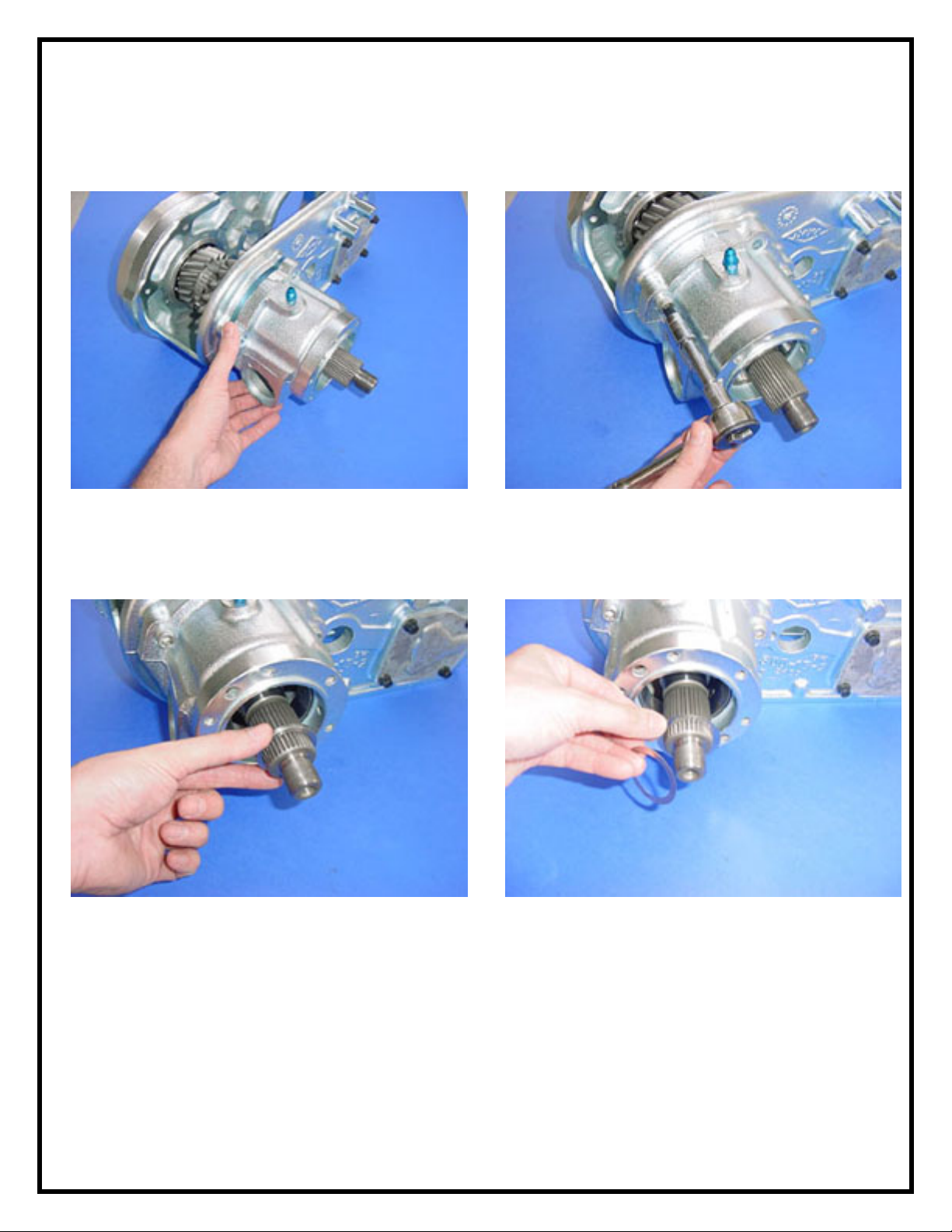
23) Apply a thin film of RTV sealant to the back of the new bearing retainer
and install it onto the case. Use the new bolts supplied in the kit to secure
the housing (Fig.27,28).
FIG: 27
24) Using the shim combination you determined previously, Install the
spacer ring and shim pack onto the shaft (Fig.29,30).
FIG: 28
FIG: 29
FIG: 30
15
Page 16
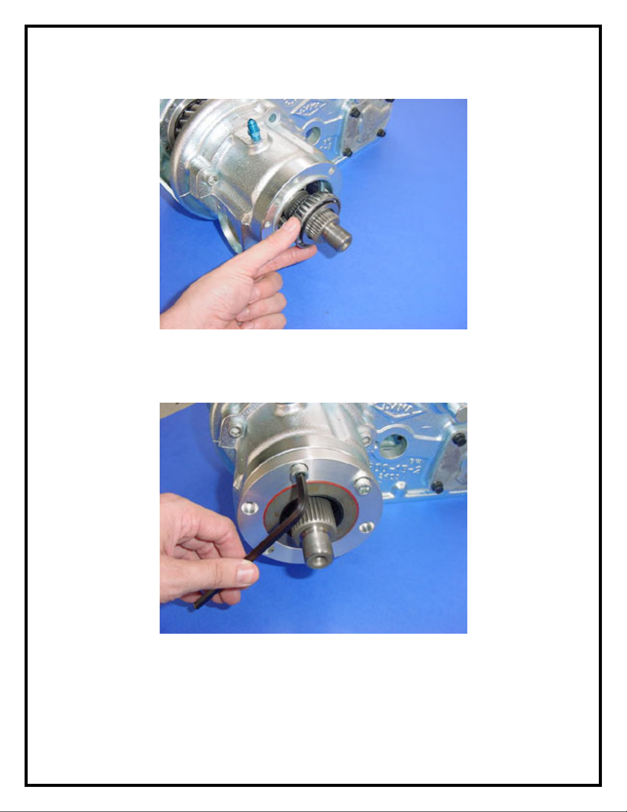
25) Install the tapered roller bearing onto the shaft (Fig.31).
FIG: 31
26) Install the seal retainer using the 6 bolts supplied in the kit. Apply a thin
film of RTV to the back side of the retainer before installation (Fig.32).
FIG: 32
16
Page 17
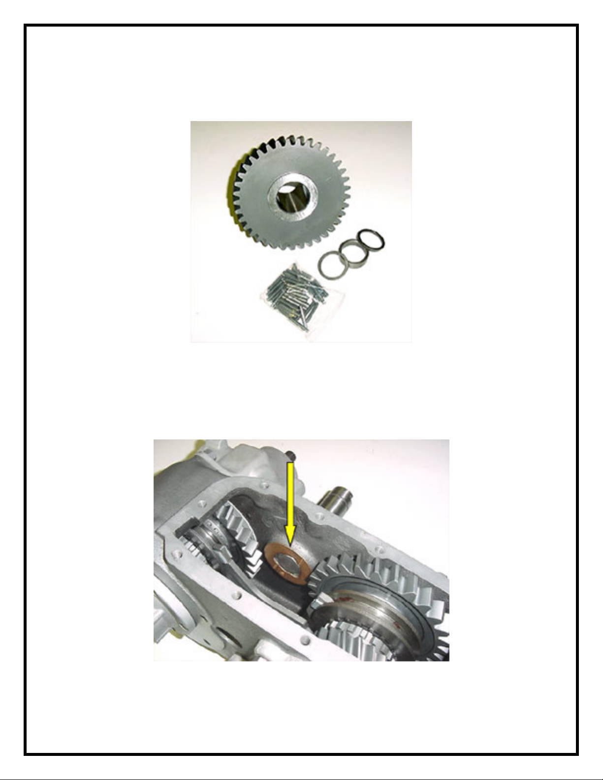
27) Install the needle bearings into the idler gear using a thick grease
(Fig.33). Remember to install the three steel rings along with the needle
bearings. Be sure that all needle bearings are installed.
FIG: 33
28) Place one of the thrust washers into the case as shown (Fig.34). Coat
both sides of the washer with a thick grease and place it into the case
properly. You can use the cross shaft as shown to hold the washer in place as
you lower the idler gear into place (later in the installation of the gear).
FIG: 34
17
Page 18
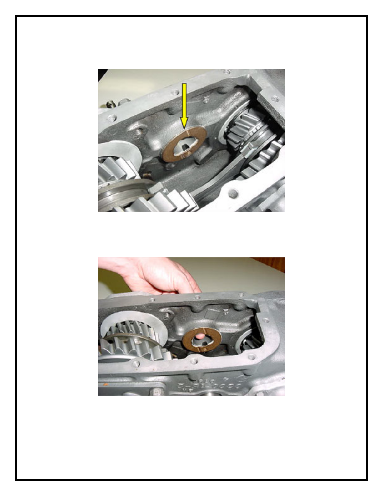
29) Place the second thrust washer into the case as shown. Again coat both
sides with grease. The washer should stay in place easily (Fig.35).
FIG: 35
30) As you lower the idler into place in the next step, you can hold the thrust
washer into place with your finger tip as shown (Fig.36).
FIG: 36
18
Page 19
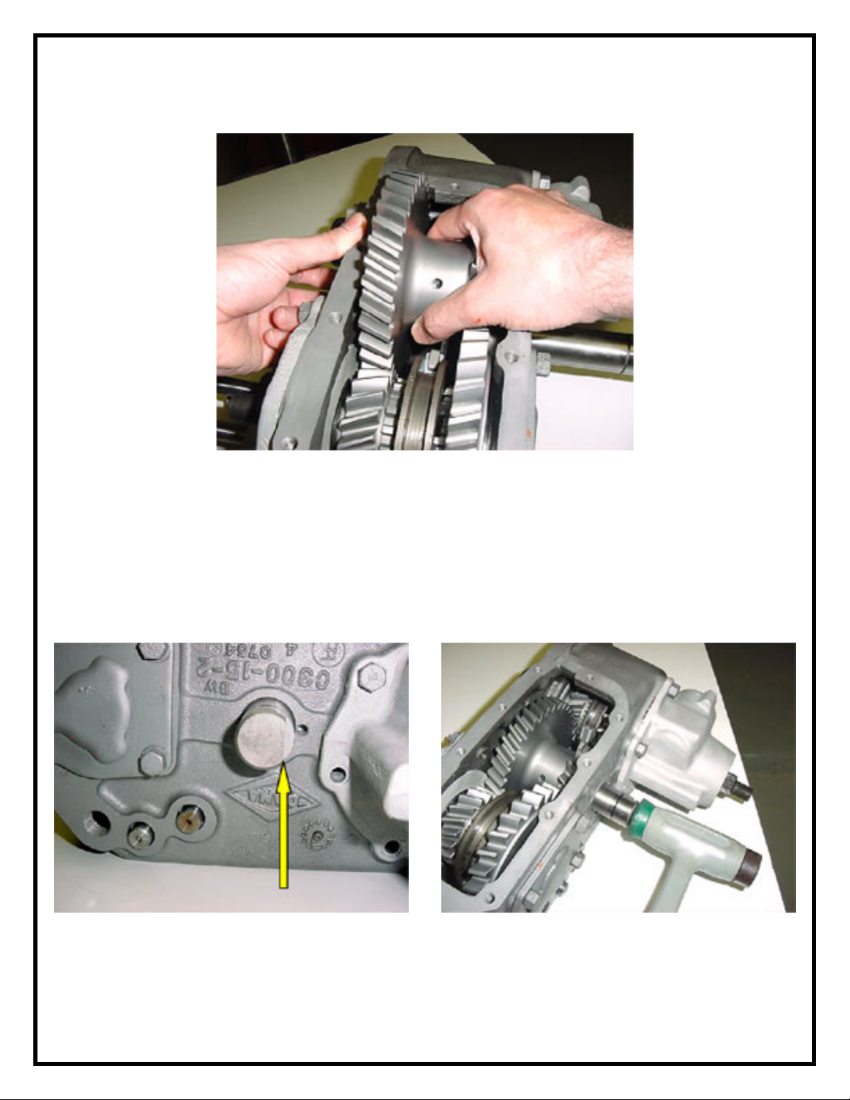
31) Roll the idler gear into place rotating it as it is lowered (Fig.37).
FIG: 37
32) When the idler gear is located properly, the intermediate shaft can be
easily pushed through the center of the idler gear. Pay close attention and be
sure all of the needle bearings remain in place during this procedure. Align
the intermediate shaft with the flat side in the position shown. This will allow
the retainer plate and bolt to be installed after the intermediate shaft is
tapped into the final position (Fig.38,39). Install the shift rail caps if they
have been removed.
FIG: 38
FIG: 39
19
Page 20
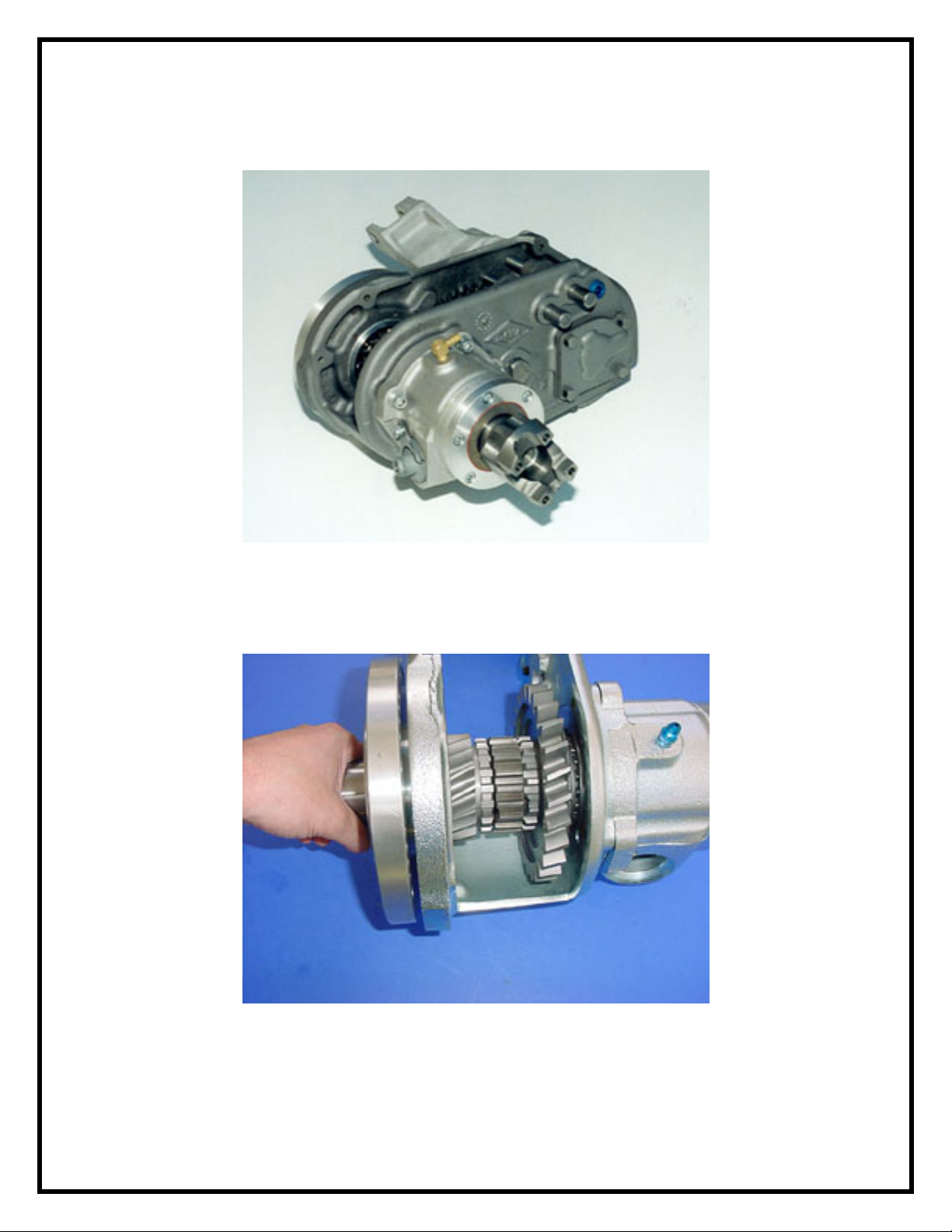
33) Install the yoke, rubber nut seal, and lock nut. Torque to #180 lb-ft
(Fig.40). Discard setup nut used in step 16.
FIG: 40
34) Remove the input retainer assembly you installed temporarily in step 15
(Fig.41).
FIG: 41
35) If you have left the slider ring, forks, and shift tower assembly in place
(from step #6) throughout this reassembly, apply RTV to the back of the
input retainer assembly and reinstall it. If you have removed the slider ring
20
Page 21

during disassembly (step #8), it will be necessary to reinstall the slider ring
onto the rear output shaft and gear.
36) If the shift rail assembly was removed in step #8, reinstall it now. You
will have to guide the two rails through the two forks as the aluminum
housing assembly is installed. Also, gasket surfaces will have to be cleaned
and sealant applied to the housing before it is reinstalled.
37) Reinstall the intermediate gear and shaft. The installation is complete.
21
 Loading...