

Page 1

L
o
M
a
x
™
3
0
0
L
Manufactured by JB CONVERSIONS, INC.
Part No. 2307
Instruction Rev: 2009.09.26
Kit Components
1: (2) 27 tooth gears
2: (2) 18 tooth gears
3: (1) Idler gear (37 X 14 tooth)
4: (2) Optional - Shift detent springs
5: (1) Optional - Stock shift rail
5A: (1) Custom shift rail
6: (2) Optional - Slider rings
7: (1) Input retainer clip
8: (1) Optional - Seal & Gasket Kit
9: Instruction sheet
IMPORTANT!
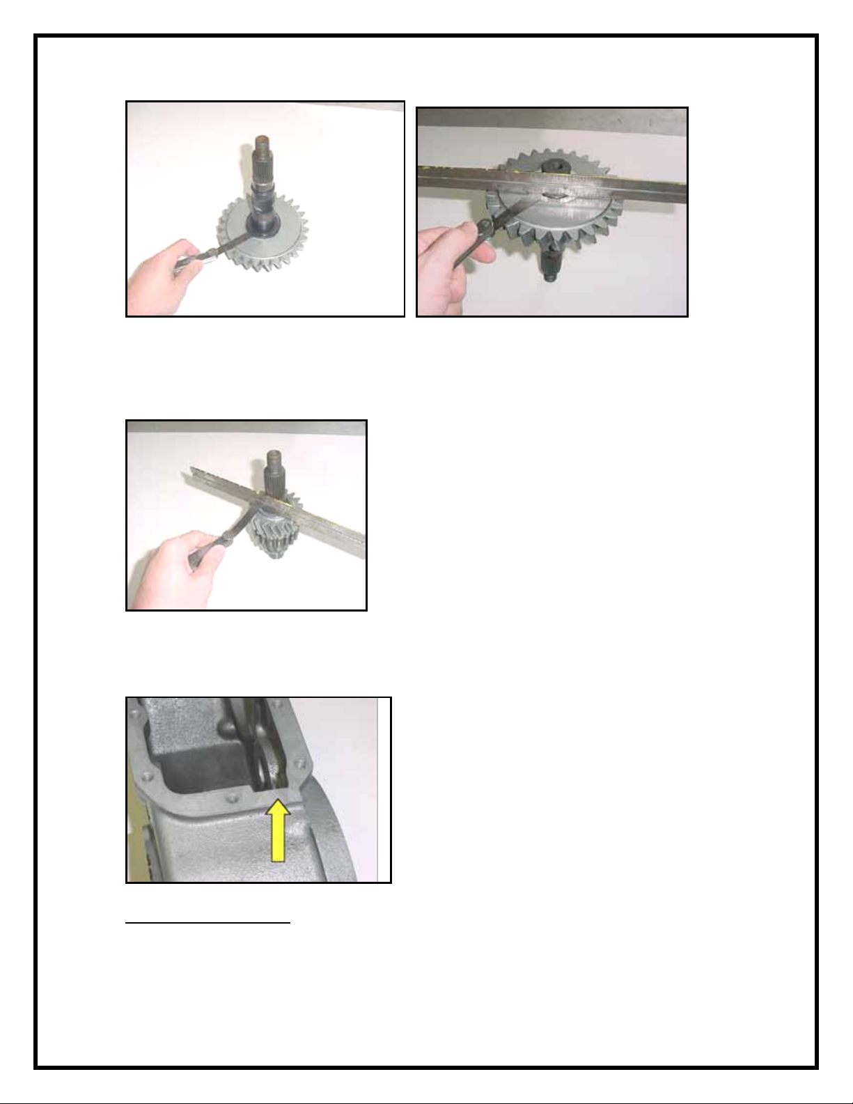
Preassembly check: After the Dana 300 has been disassembled, refer to the photos
A,B,& C below to verify gear-to-shaft clearances.
A: Place one 27 tooth LoMax helical gear and thrust washer onto the rear output
shaft as shown. Using a gap gauge, check for clearance between the thrust
washer and the “grind” (polished) surface of the gear. The gear face should NOT
contact the thrust washer.
B: Place the 2
Using a gap gauge, check for clearance between the grinded gear face and the
shoulder on the shaft. Use a straight edge as shown.
o
4-TO-1 REDUCTION GEARSET
Installation Instructions for the
nd
27 tooth LoMax helical gear onto the front output shaft as shown.
M
Dana 300 Transfer Case
a
Phone: 337-625-2379
x
3
0
0
Page 2
(A) (B)
C: Place the 18 tooth LoMax helical gear onto the front output shaft as shown.
Using a gap gauge, check for clearance between the polished, grinded gear face
and the shoulder on the shaft. Use a straight edge as shown.
(C)
After the case has been totally disassembled, grind a small area on the case for gear
clearance. Thoroughly clean the case after this process is completed.
DISASSEMBLY:
1) Clean and drain your Dana 300.
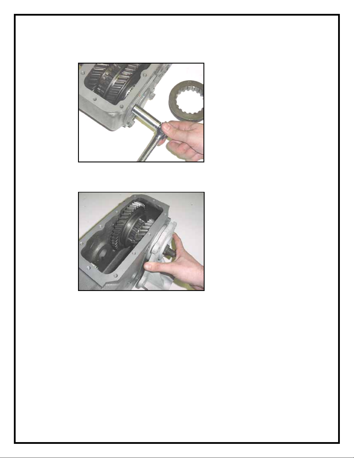
2) Remove the front and rear output yokes/seals and inspection cover (Fig.1).
You will need a 1-1/8” socket and possibly a gear puller.
Page 3
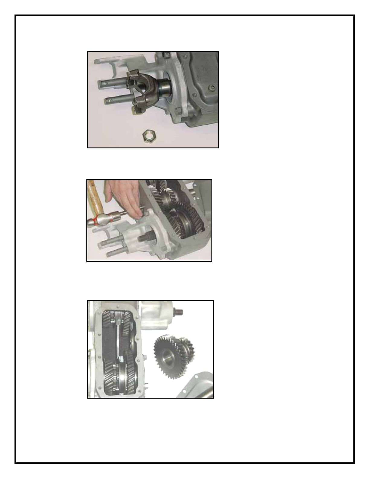
Fig.1
3) Remove the 5/16” retainer bolt and plate for the cross shaft. Using a brass or
wood drift, remove the cross shaft as shown (Fig.2).
Fig.2
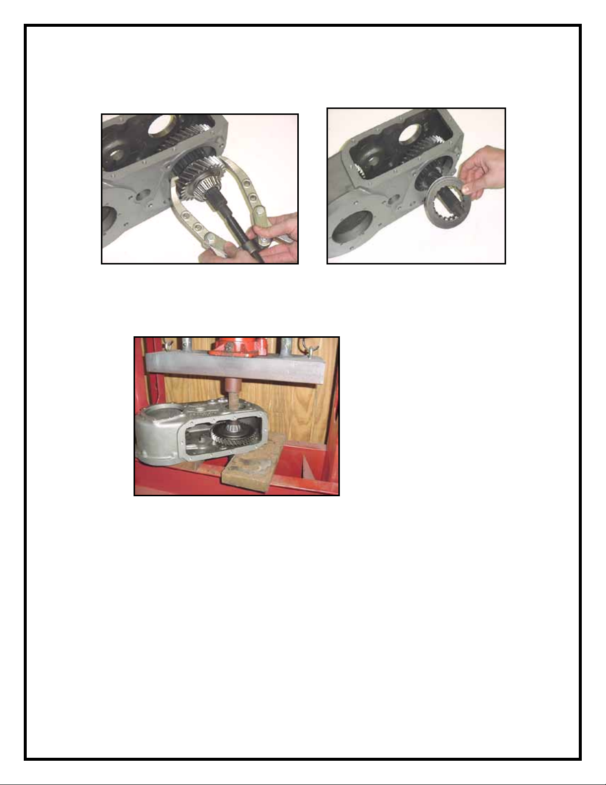
4) Remove the idler gear from the case (Fig. 3). Be aware of the needle
bearings and 3 retaining rings in the center bore of the idler gear. Retain or
replace during final assembly as desired.
Fig.3
Page 4
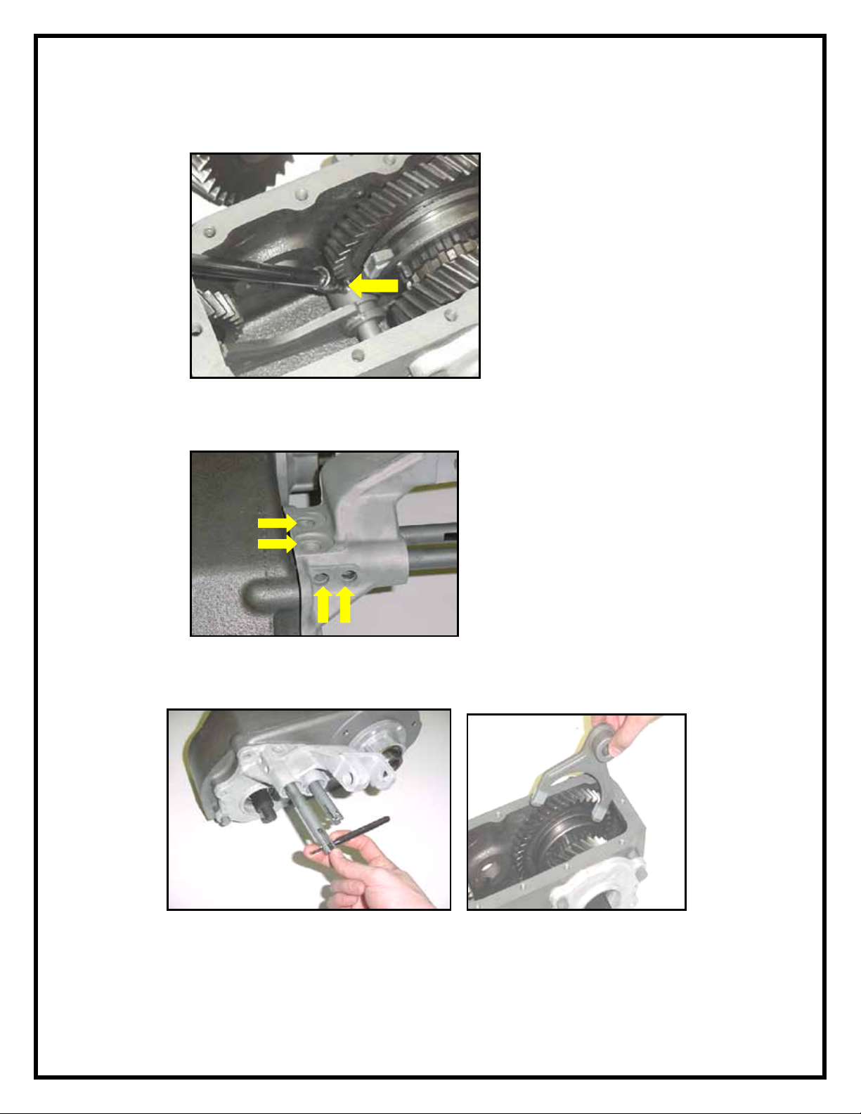
5) Using a 3/16” allen socket, remove the two shift fork set
Screws (Fig.4).
Fig.4
6) Remove the two “pressed” detent plugs, switch, and threaded plug from the
front bearing retainer housing (Fig.5).
Fig.5
7) Rotate the shift rails and slide them out of the case (Fig. 6). Turn the case
back over and remove the shift forks beginning with the smaller fork (Fig.6a).
Fig.6 Fig.6a
Page 5
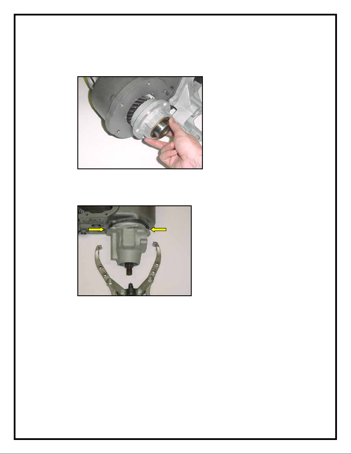
8) Remove the 6 allen or torx screws holding the input bearing retainer into the
case (Fig.7). You will need to use a rubber hammer to tap the retainer loose
from the case. Use a screwdriver or pry bar to work the retainer forward
from the case.
Fig.7
9) Remove the speedometer drive gear from the rear output bearing retainer
housing (Fig.8). Using a 2-jaw puller, remove the housing from the transfer
case. Keep the shims located behind the rear bearing.
Fig.8
Page 6
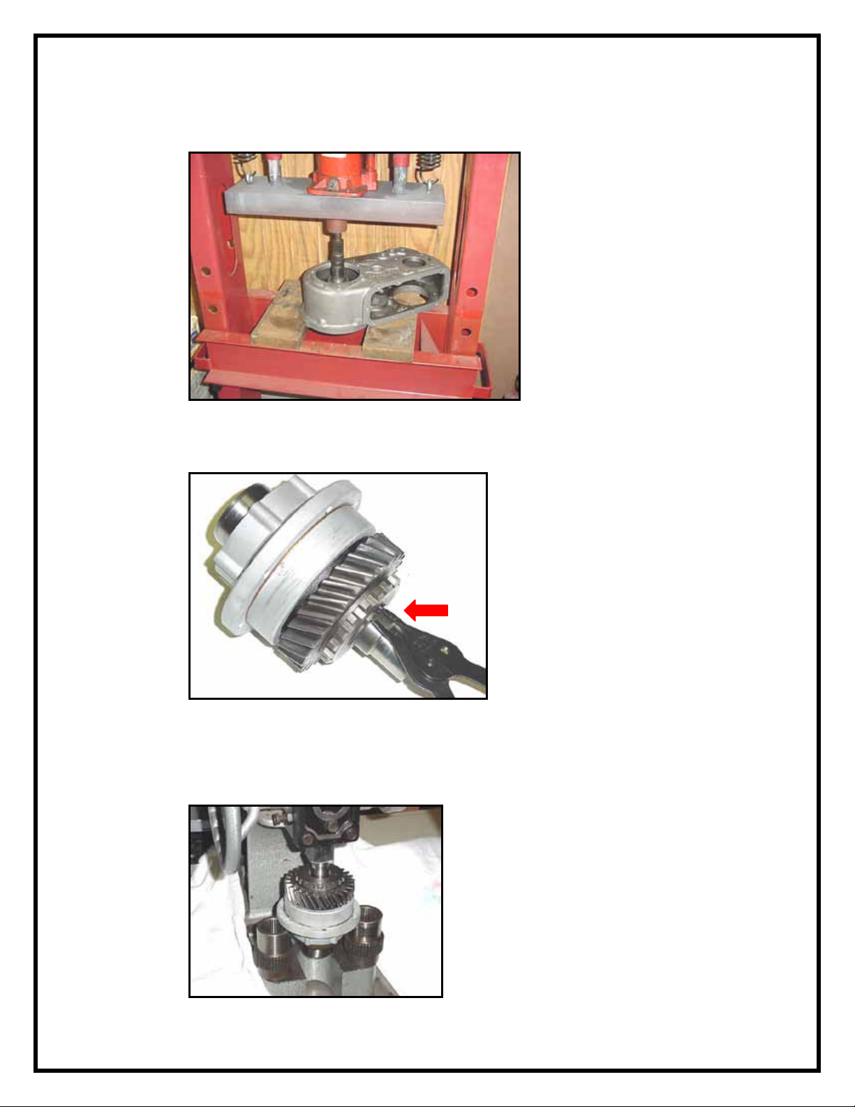
10) Remove the rear bearing retainer plate and shims from the case followed by
the bearing cup (Fig.9).
Fig.9
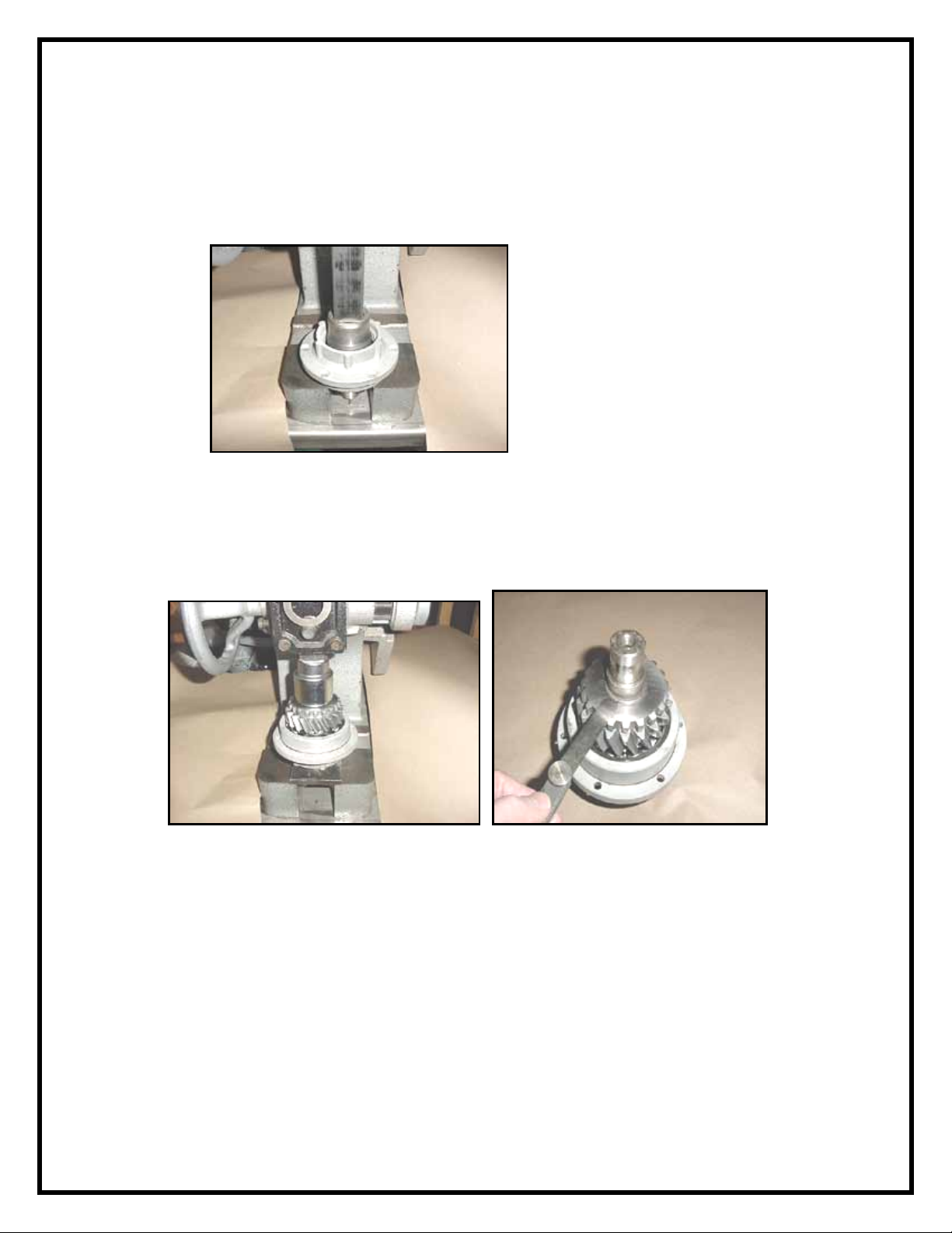
11) Remove the front output bearing retainer using a rubber hammer and pry
bar (Fig. 10).
Fig.10
Page 7
12) Using a 2-jaw puller remove the helical gear and roller bearing as shown
(Fig. 11). Remove the slider as shown (Fig.11a).
Fig.11 Fig.11a
13) Position the case in a vertical press and remove the front output shaft from
the helical gear/roller bearing (Fig. 12).
Fig.12
Page 8
14) Reposition the case in the vertical press and remove the rear output shaft
from the helical Gear/roller bearing (Fig. 13).
Fig.13
15) Disassemble the input gear assembly beginning with the removal of the
retaining ring (Fig. 14).
Fig.14
16) Position the input gear assembly in a vertical press and push the input gear
out of the ball bearing (Fig. 15). The seal may be forced out of the housing
as the input shaft is pressed out. Discard the seal. Retain the shims
located between the input gear shoulder and ball bearing.
Fig.15
Page 9
17) With the original shims still in place on the stock input shaft, reverse the
process in #16 above and press the input gear back into the stock ball
bearing (Fig. 16). Before pressing the gear, use a small amount of grease
to hold the shims onto the input gear. This will keep them from dropping
onto the bearing and becoming damaged during the press.
Fig.16
18) Push the new LoMax helical drive gear onto the splines of the stock input
shaft followed by the new retaining ring. Verify 0.00”-0.003” gap below the
retaining ring. Adjust shims as necessary to achieve the proper gap (Fig.
17,17a). We recommend replacing the oil seal in the aluminum bearing
housing with the double lip seal supplied in the optional Seal & Gasket Kit.
Fig.17 Fig.17a
Page 10
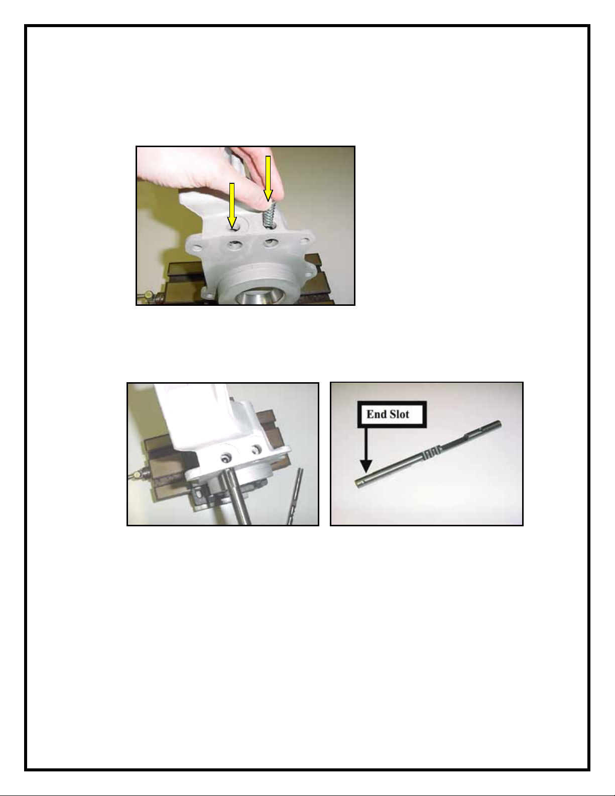
19) Begin installation of the shift rails by mounting the bearing retainer housing
in a smooth-jaw clamp. Install two new springs (Fig.18) into each of the
two vertical bores in the housing. These springs, which can be purchased
as an option, are stiffer than stock therefore reducing the tendency of twin
stick arrangements to cause the tcase to pop out of gear while under load.
Fig.18
20) Place the original detent ball on top of the exposed spring in the left bore
(Fig.19). Begin this procedure on the left rail as shown. Position the proper
shift rail (Fig.19a) with the end-slot facing vertical. Push the rail up to the
detent ball.
Fig.19 Fig.19a
Page 11
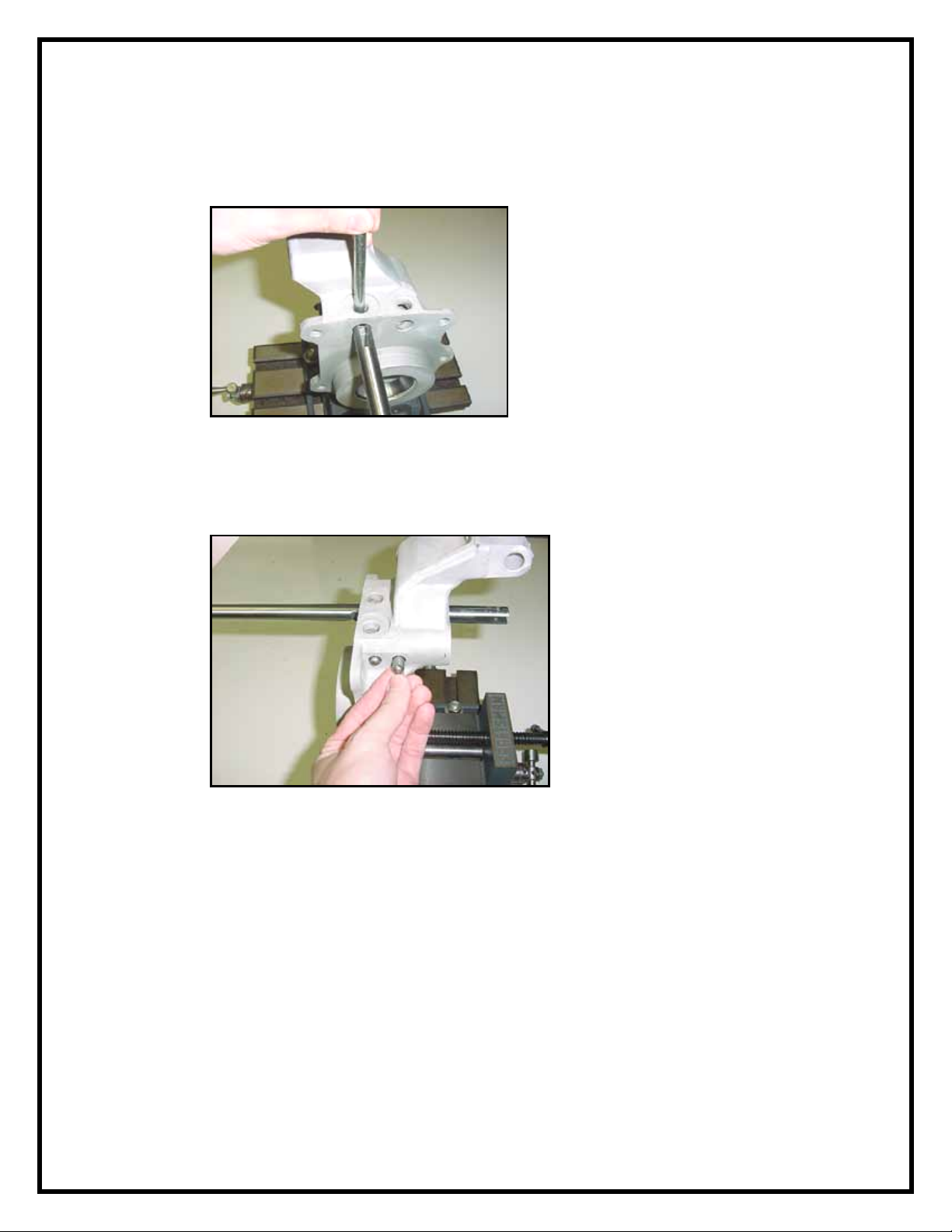
21) Depress the detent ball with a punch while pushing the rail through the
housing (Fig.20). Push the rail forward until 4-11/16” of the rail remains
exposed on the outside of the housing. Do not rotate the rail while
performing this step.
Fig.20
22) Insert the pill-shaped slider plugs into the horizontal bores as shown
(Fig.21). Push them as far inward as they will go. They should seat in the
pockets of the 1
nd
rail) and see no obstruction caused by the “pills”.
2
st
rail. You should be able to look through the bore (for the
Fig.21
Page 12
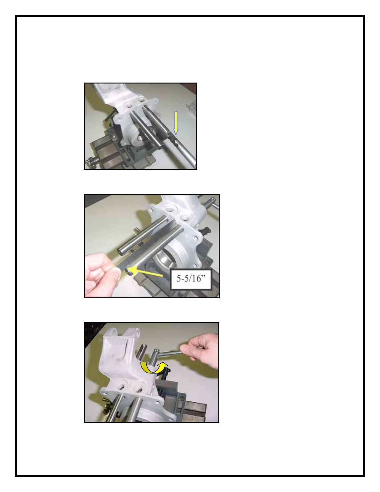
23) Position the 2nd rail and detent ball as done on the 1st rail. Depress the
detent ball with a punch and push the rail through the housing just past the
ball. Be sure the 2
nd
rail is installed as shown (Fig.22) with the detent
pockets positioned as you see here. Do not rotate the rail while performing
this step.
Fig.22
24) Push or tap the 2
nd
rail inward until 5-5/16” of the rail remains exposed. Do
not rotate the rail at this point (Fig.23).
Fig.23
25) Roll the second rail counter-clockwise 90 degrees. You should feel the
detent ball “pop” into place securing the rail (Fig.24).
Fig.24
Page 13
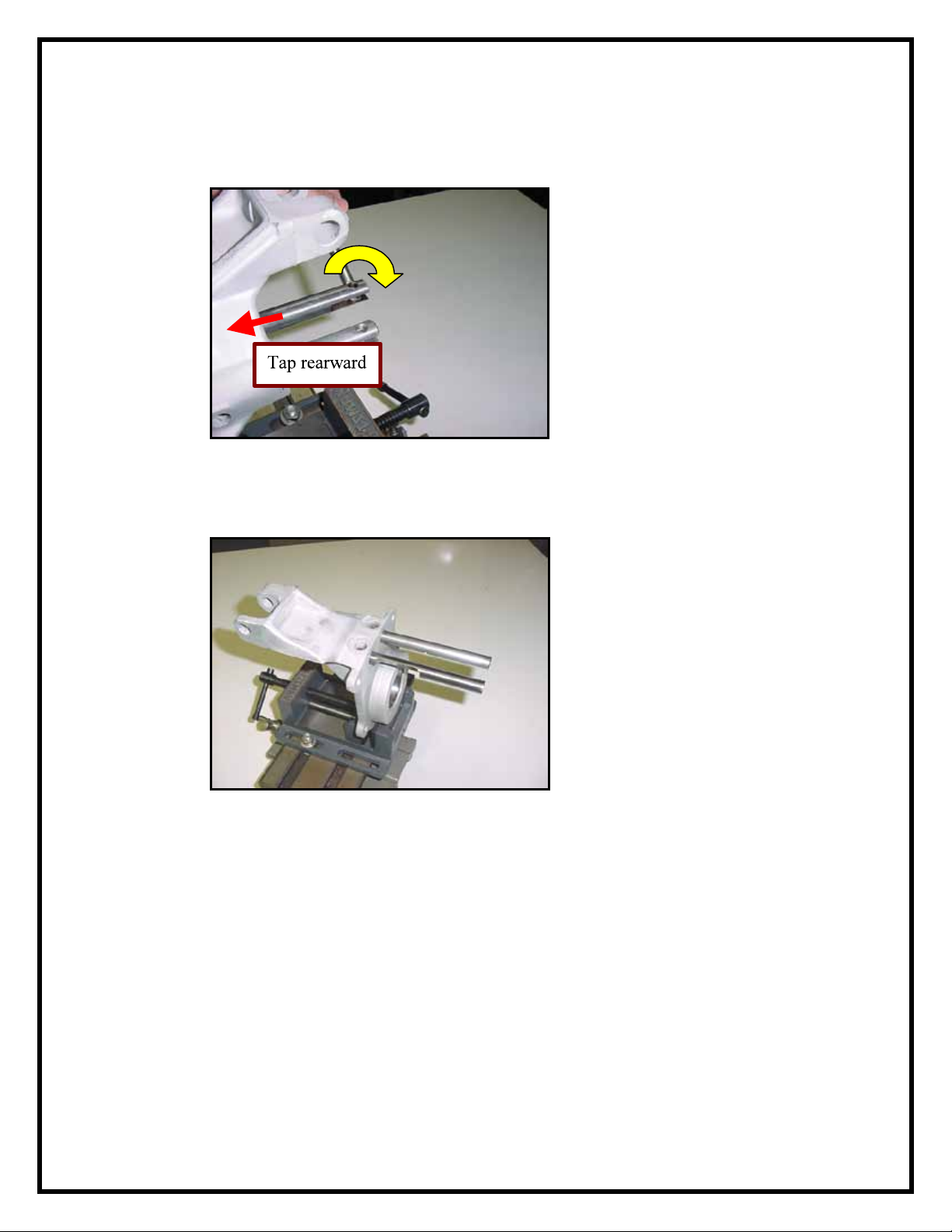
26) Roll the 1st rail 90 degrees in a clockwise rotation (Fig.25). You should not
feel the ball detent pop into place until you tap the 1
st
rail rearward a bit
after it is rotated.
Fig.25
27) Tap the 1
st
rail rearward 1 more notch to the position shown. Both rails
should now be at equal lenth from the rear face of the aluminum housing.
Leave them in this position for further assembly of the tcase (Fig.26).
Fig.26
Page 14
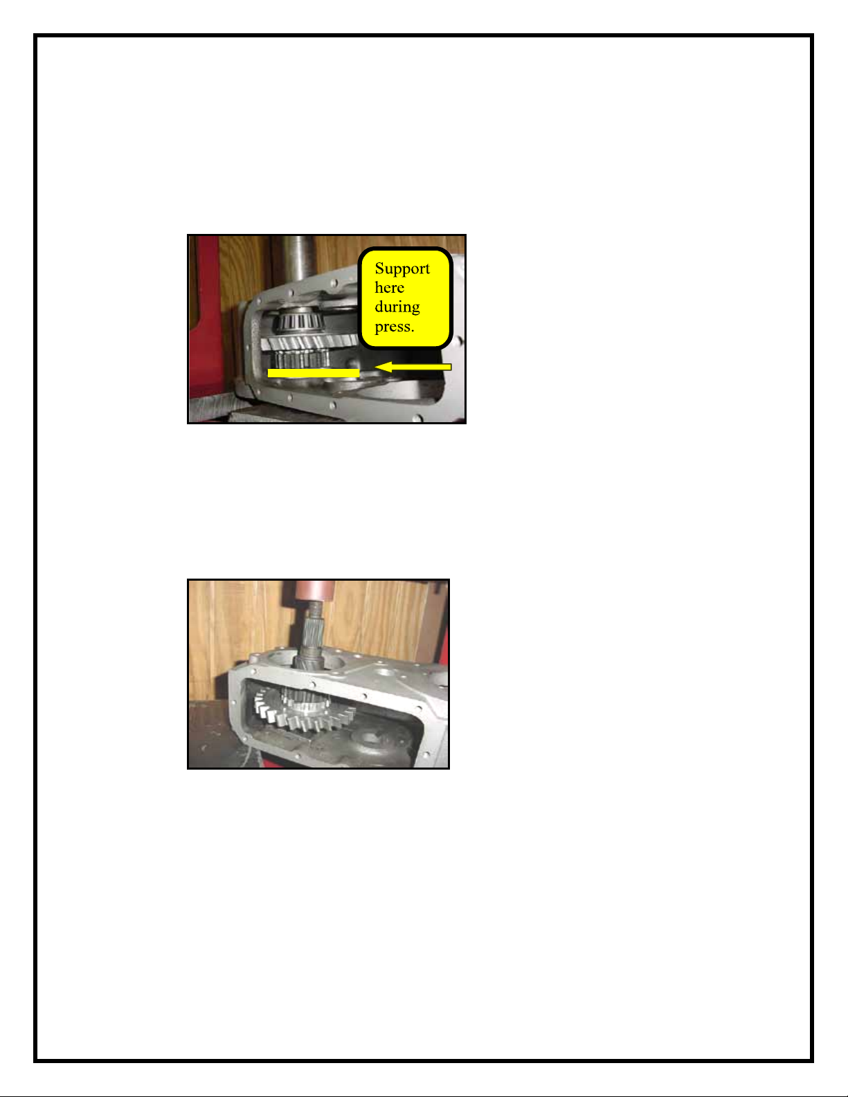
28) Position either of the two 27 tooth LoMax helical gears inside the case and
pass the rear output shaft through the case and bore of the gear. Be sure
to install the stock thrust washer onto the shaft in a position above the
helical gear. Place the case in a vertical press and press the tapered roller
bearing # 25880 onto the shaft. The bearing should stop as it contacts the
thrust washer (Fig. 27). Verify the helical gear can turn free after the press
operation is completed.
Fig.27
29) Position the second 27 tooth LoMax helical gear inside the case and pass the
front output shaft through the case into the bore of the gear. Place the
case in a vertical press and press the tapered roller bearing # 86649 onto
the shaft (under the gear). The bearing should stop as it contacts the
shoulder on the shaft (Fig. 28). During the press procedure, support the
bearing properly so not to damage the cage around the rollers. Verify the
helical gear can turn free after the press operation is completed.
Fig.28
Page 15
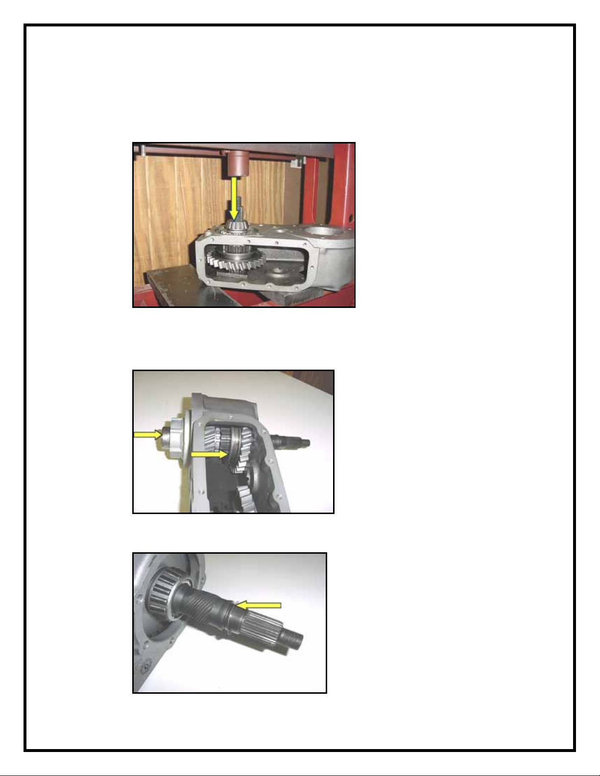
30) Reposition the case in the vertical press to allow the new slider ring and 18
tooth LoMax helical gear to be placed on the front output shaft with a
tapered roller bearing # 86649. Press the bearing onto the shaft until it
stops at the shaft shoulder (Fig.29). Verify the 18 tooth helical gear can
turn free after the press operation is completed. Do not press against the
cage of the bearing.
Fig.29
31) Place the remaining slider ring onto the clutch teeth of the rear output
shaft. Install the input gear cluster into the front of the case followed by
the 6 allen or torx screws (Fig.30). Use RTV to seal the aluminum input
housing.
Fig.30
32) Place the original rear bearing shims onto the rear output shaft in their
original location (Fig.31).
Fig.31
Page 16
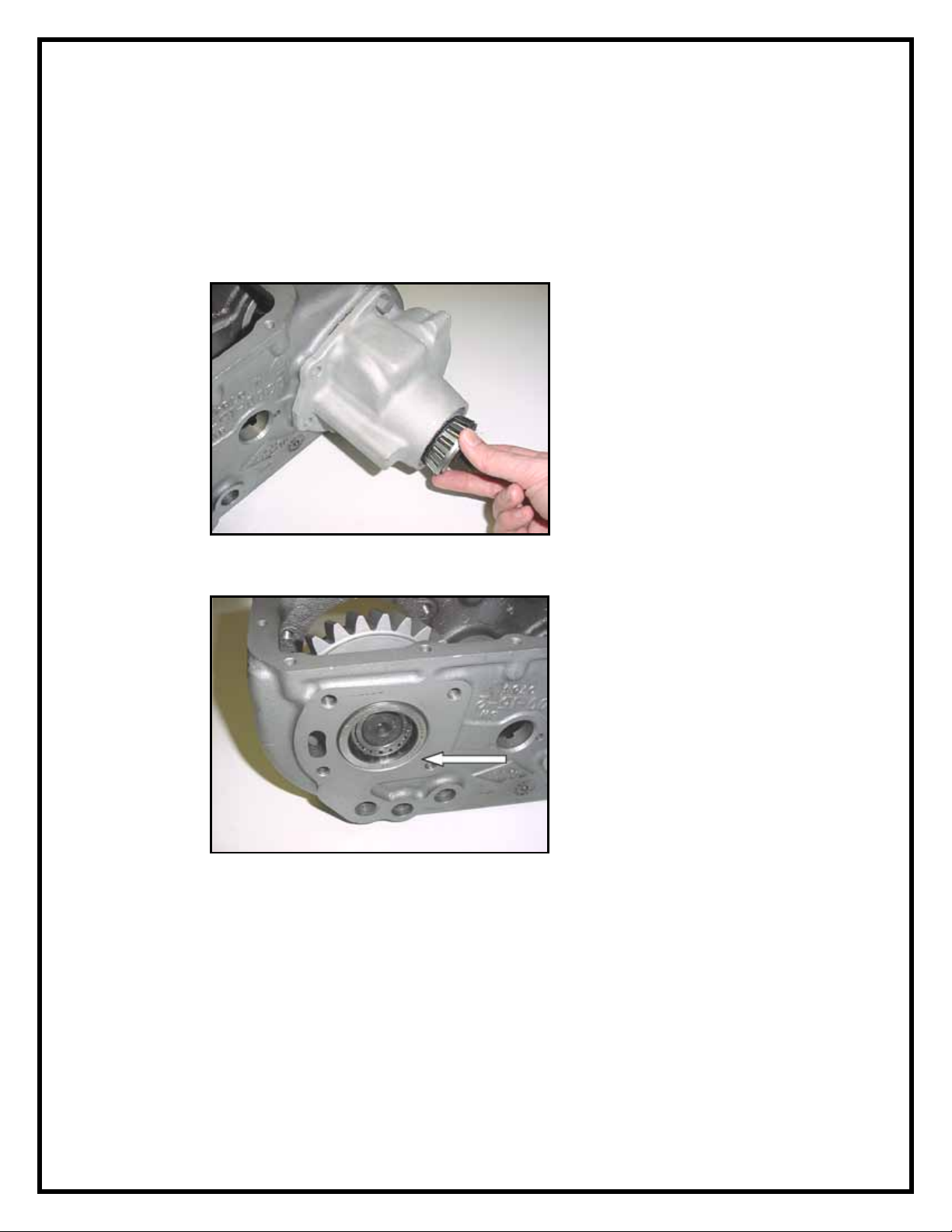
33) Bolt the rear bearing housing onto the case followed by the tapered roller
bearing #15117 (Fig.32). Install the rear output yoke and seal (available
with the optional Seal & Gasket Kit). Torque to 100 lb-ft. Verify end play at
0.002”-0.005”. The installation of the LoMax gears does not affect shaft
end play however if new bearings are being installed, end play may be
effected. If end play is incorrect for any reason, remove the rear bearing
housing and reshim the bearing.
Fig.32
34) Place the bearing cup #M86610 into the rear bore of the case (Fig.33).
Fig.33
Page 17
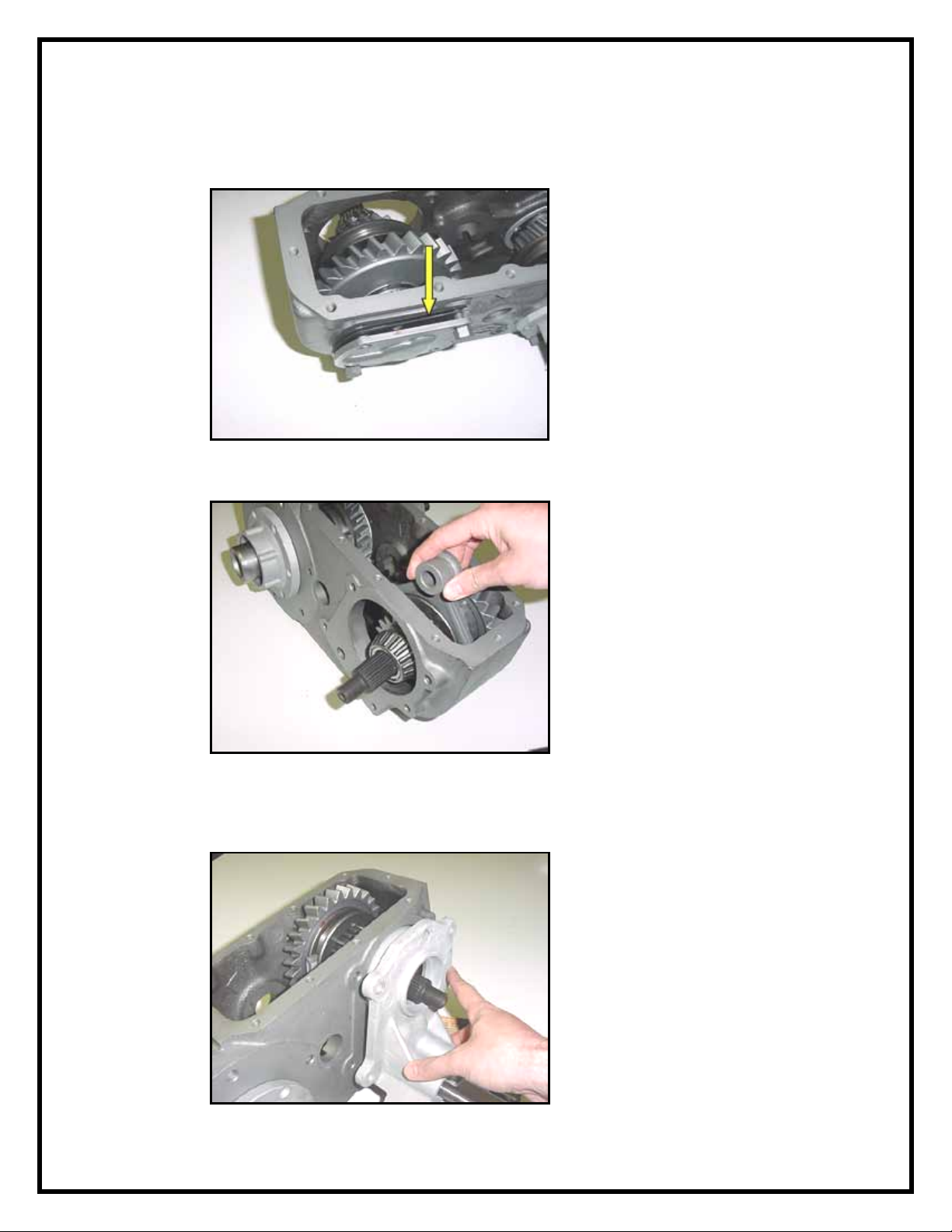
35) Install the retainer plate (Fig.34) and original shim pack in place behind the
bearing cup. Do not seal this plate yet as you may need to reshim if end
play is effected by a new bearing.
Fig.34
36) Arrange the shift forks in the case beginning with the large fork (Fig.35).
Fig.35
37) Insert the aluminum housing/shift rails through the case. The rails should
be worked through the forks as this is done. A bit of oil on the forks will
help them slide through the forks (Fig.36).
Fig.36
Page 18
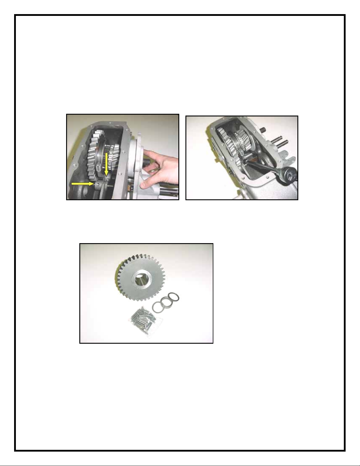
38) Bolt the housing in place. Install the 2 set screws into the forks using
Loctite (Fig.37,37a). You will need to verify shaft end play at this point.
End play should be 0.003”-0.006” on the front output shaft. If new
bearings were installed, you may need to adjust the shim pack noted in step
35. Once proper end play is verified, remove the bearing plate installed in
step 35, apply a seal with RTV and reinstall. Install the front output shaft
seal (available with the optional Seal & Gasket Kit), yoke, and nut. Torque
to 100 lb.ft..
Fig.37 Fig.37a.
39) Install the needle bearings into the idler gear using a thick grease (Fig.38).
Remember to install the three steel rings along with the needle bearings.
Be sure that all needle bearings are installed.
Fig.38
Page 19
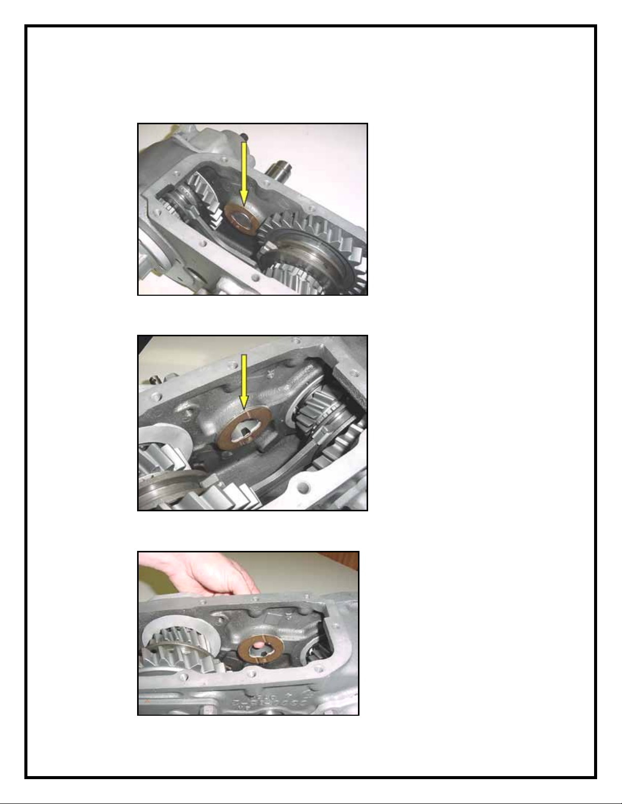
40) Place one of the thrust washers into the case as shown. Coat both sides of
the washer with a tacky grease and place it into the case properly. You can
use the cross shaft as shown to hold the washer in place as you lower the
idler gear into place in step 45 (Fig.39).
Fig.39
41) Place the second thrust washer into the case as shown. Again coat both
sides with grease. The washer should stay in place easily (Fig.40).
Fig.40
42) As you lower the idler gear into place in the next step, you can hold the
thrust washer into place with your finger tip as shown (Fig.41).
Fig.41
Page 20
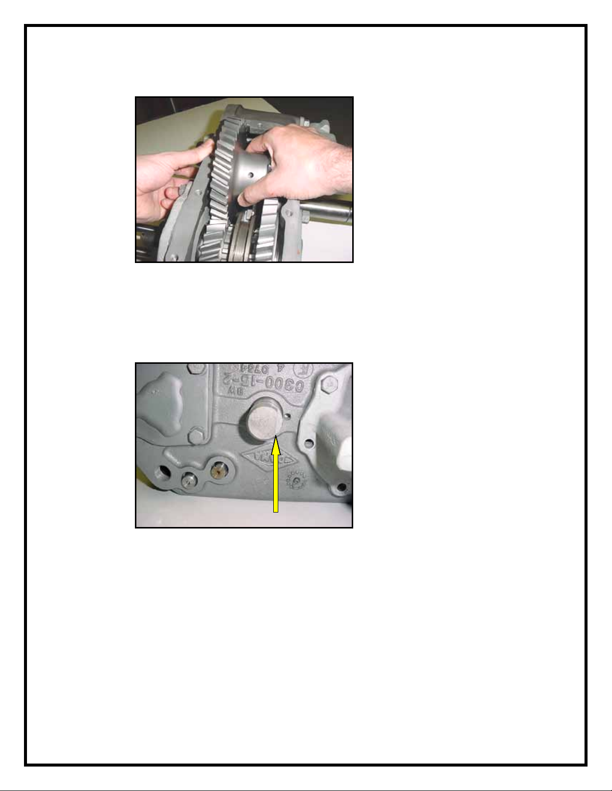
43) Roll the idler gear into place rotating it as it is lowered (Fig.42)
Fig.42
44) When the idler gear is located properly, the cross shaft can be easily pushed
through the center of the idler gear. Pay close attention to be sure all of
the needle bearings remain in place during this procedure. Align the cross
shaft with the flat side in the position shown. This will allow the retainer
plate and bolt to be installed after the cross shaft is tapped into the final
position (Fig.43). Install the shift rail caps if they have been removed.
Fig.43
Page 21
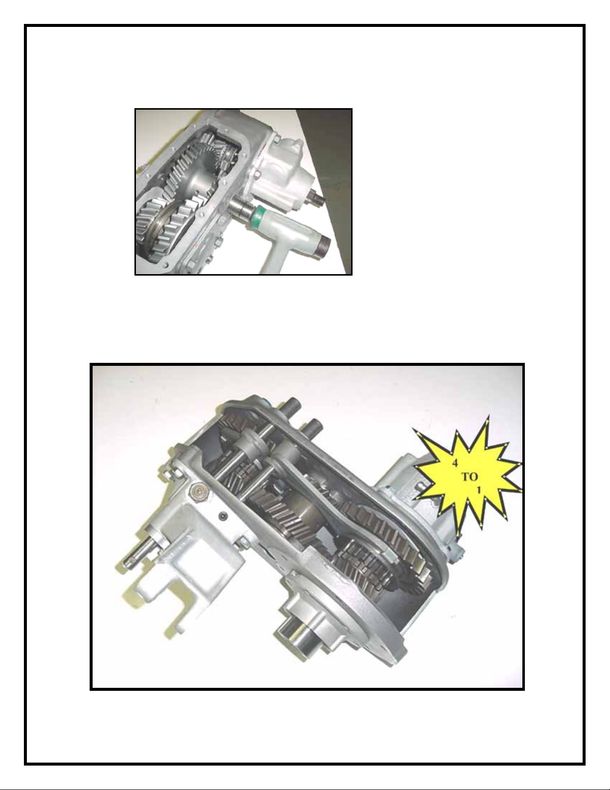
45) Using a brass drift or dead-blow hammer, tap the cross shaft into place
such that the retainer plate and bolt can be installed (Fig.44).
Fig. 44
46) Install the inspection cover and gasket (available with the optional Seal &
Gasket Kit) using a thin coating of RTV sealant. Install the speedometer
gear assembly into the rear bearing housing in the same rotational
orientation as it was previously installed. This completes the installation of
the LoMax gear set.
 Loading...