

Page 1

1
HD Super Short SYE Kit
for the
NP231C or NP233C
Manufactured by JB CONVERSIONS, INC.
Phone: 337-625-2379
Installation Instructions for the
NP231C or NP233C Transfer Case
Part No. 16-1206
Instruction Rev: 2009.10.28
Kit Components
1) Custom rear bearing housing (assembled)
2) 32 spline HD mainshaft
3) 1310 CV end yoke
4) Custom tone wheel
Applications: All applications of the NP231 or NP233 requiring a GM
speed sensor.
Note: Customer reuses existing GM speed sensor. If your sensor is
damaged or missing, a replacement sensor can be purchased as an
option.
Page 2
2
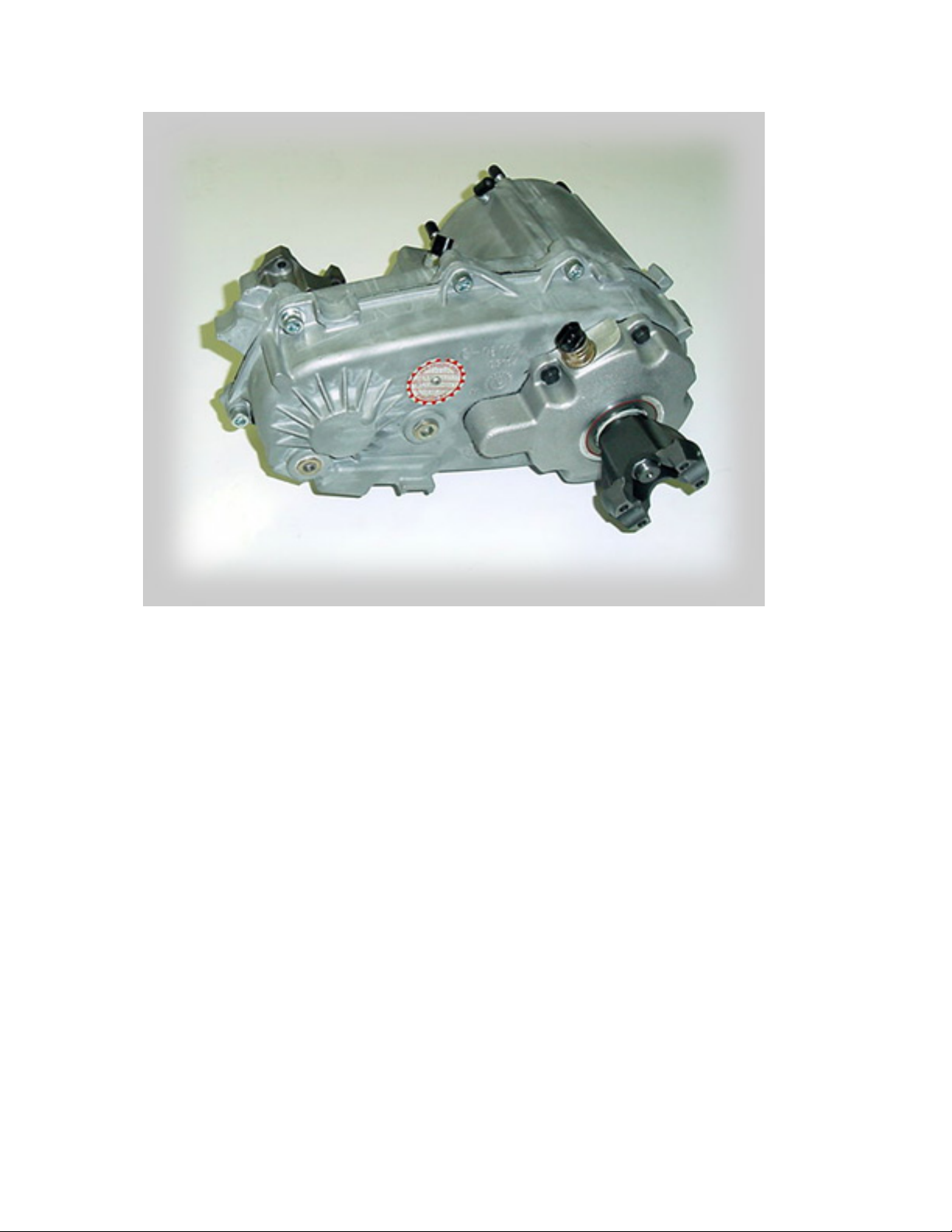
Installed photo.
Installation Instructions
Note: This kit can be installed without removing the transfer case
from the vehicle however it is recommended that the unit be removed
to ease installation of the SYE kit.
1) Drain the fluid from the transfer case. This kit can be installed while
the transfer case remains in the vehicle however, removal is
recommended for an easier installation.
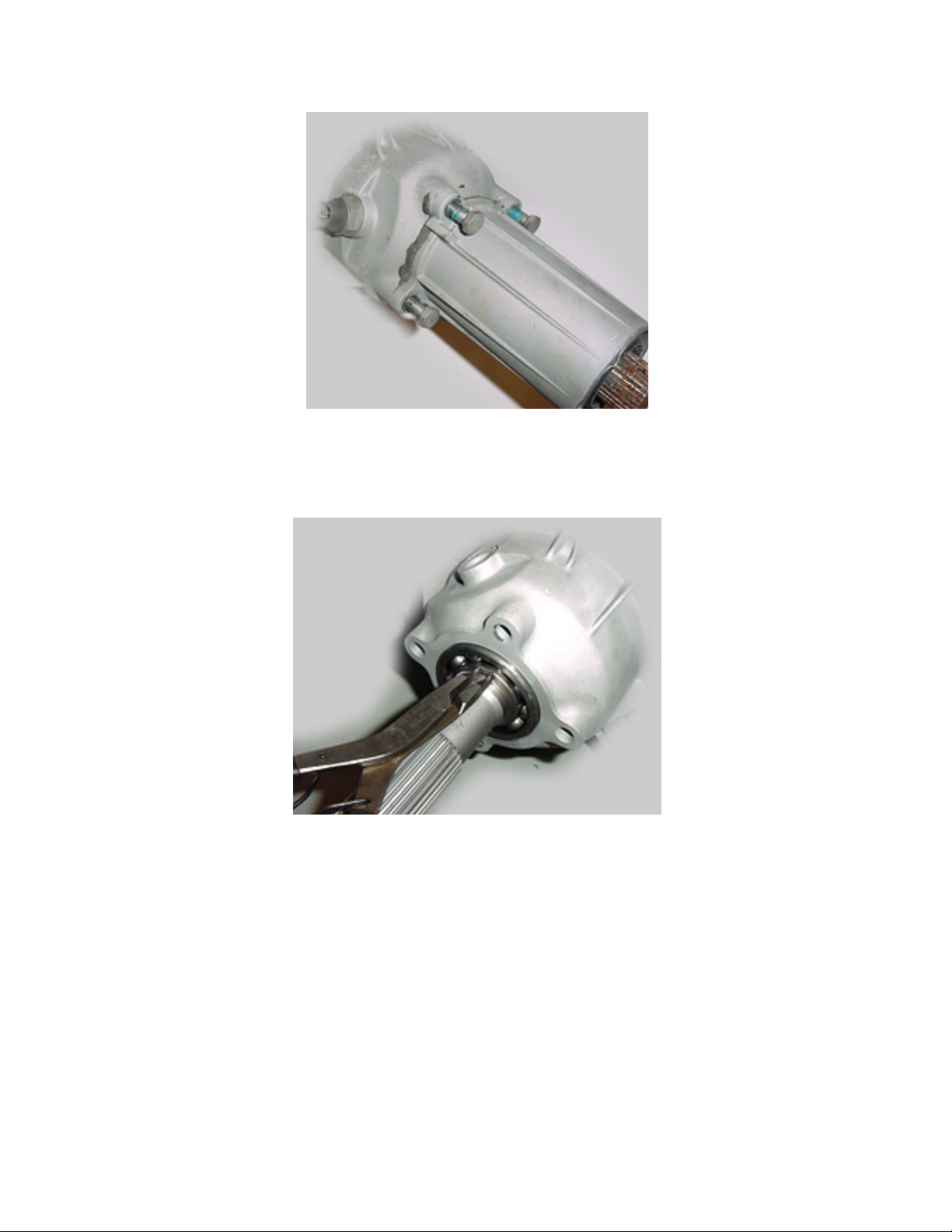
2) Remove the 10mm bolts (4) holding the tail cone onto the bearing
housing (Fig.1).
Page 3
3
FIG: 1
3) Remove the retaining ring (Fig.2).
FIG: 2
4) Remove the 8mm bolts (5) holding the rear bearing housing onto
the rear case half.
5) Remove the bearing housing using a pry device. Be careful not to
damage the case during this process.
Page 4
4
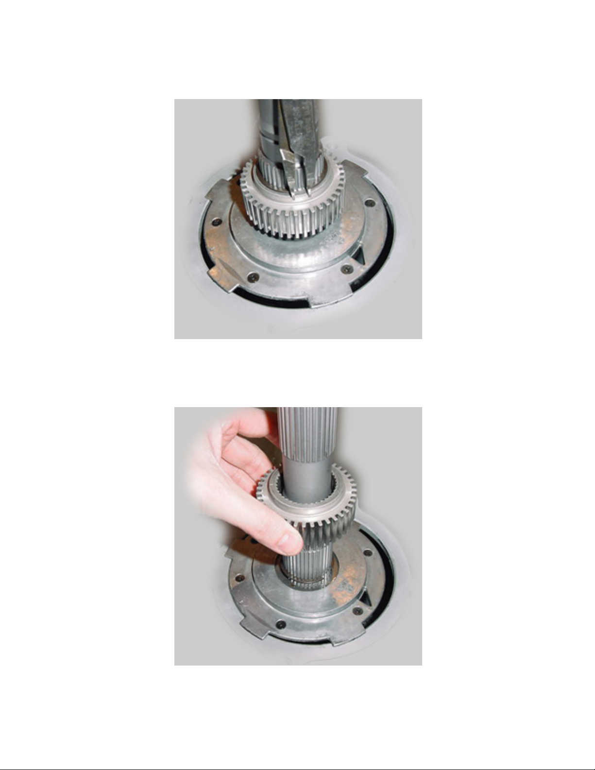
6) Remove the retaining ring above the tone wheel (Fig.3).
FIG: 3
7) Remove the tone wheel (Fig.4).
FIG: 4
Page 5
5
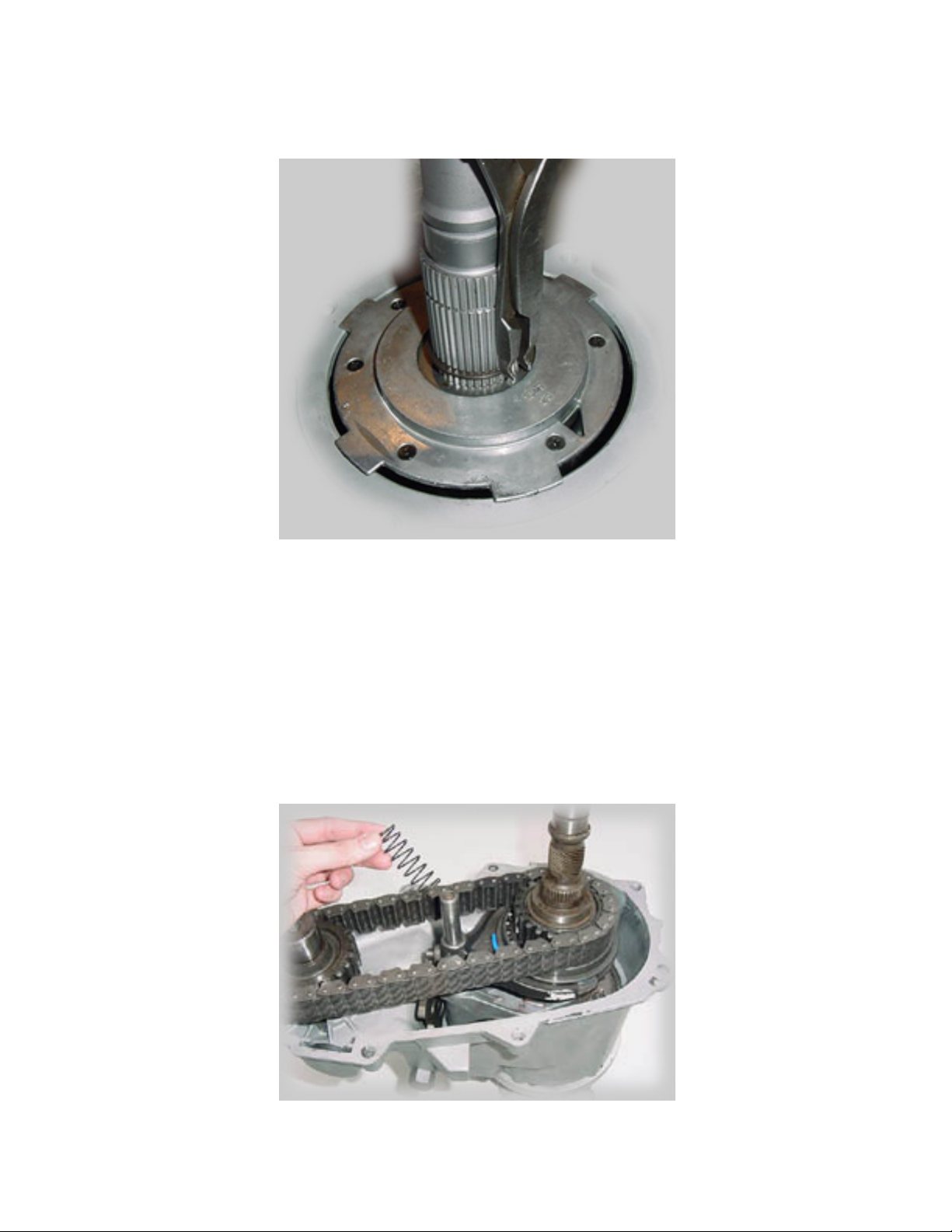
8) Remove the lower retaining ring (Fig.5).
FIG: 5
9) Remove the 10mm bolts holding the two case halves together.
10) Gently pry the two halves apart using a screwdriver. There are two
locations in the case designed for use as pry points. Only use these
two locations. They are located on the sides of the case half.
11) Remove the spring from the top of the mode fork (Fig.6).
Page 6

6
FIG: 6
12) Lift the entire mainshaft assembly, chain, and front output shaft
out of the case as an assembly (Fig.7 & Fig.8).
FIG: 7
FIG: 8
13) Using flat-head snap ring pliers, remove the large retaining ring
which holds the hub to the mainshaft (Fig.9).
FIG: 9
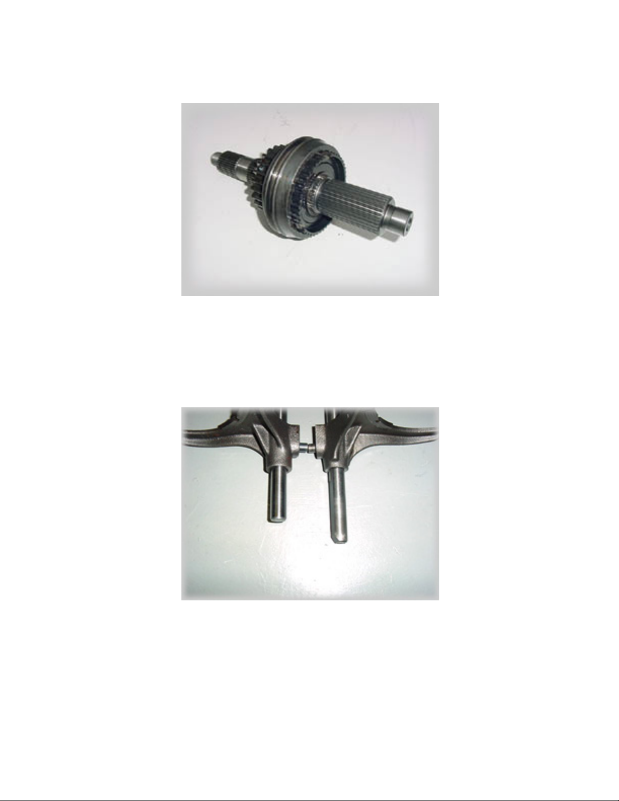
14) Install the hub and sprocket assembly onto the new mainshaft
(Fig.10). If your sprocket has needle bearings located within the main
bore, press them out and discard. It is acceptable to delete these
Page 7
7
bearings. The deletion of these bearings is per factory, NVG design.
FIG: 10
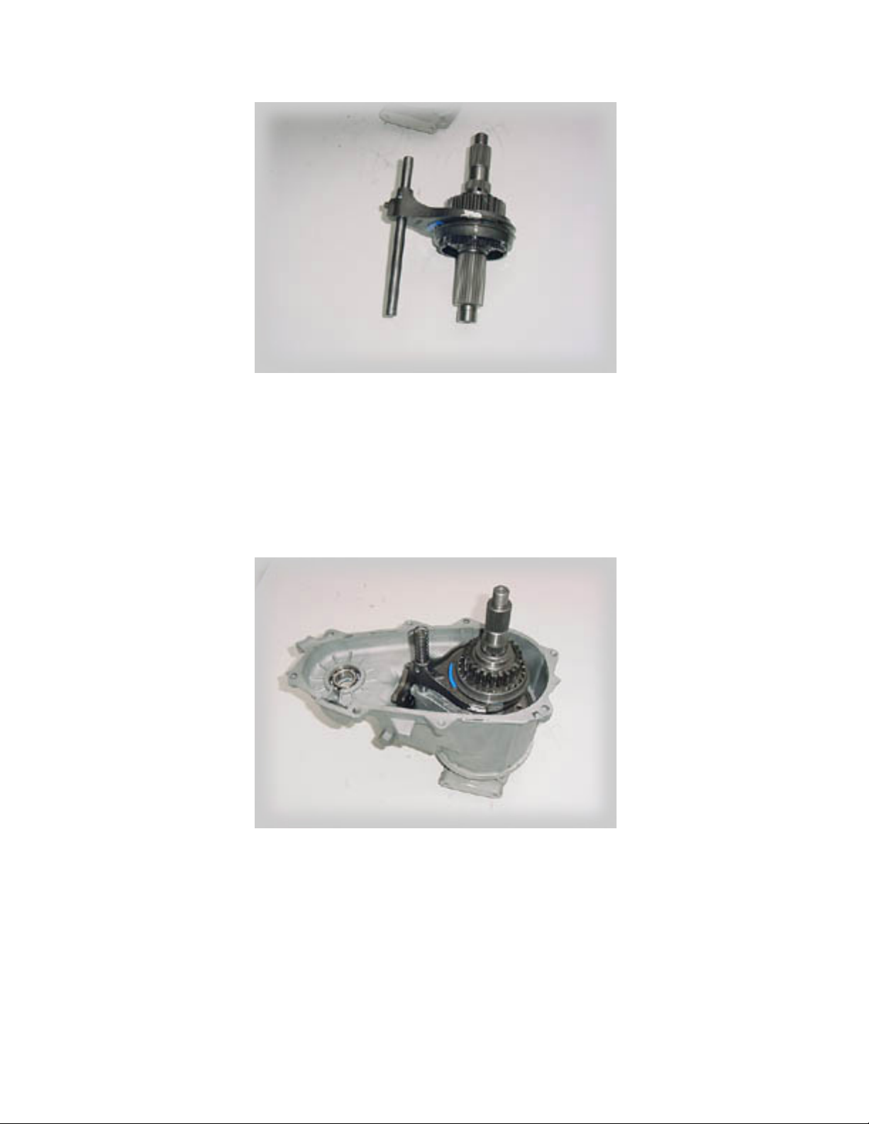
15) Verify the length of your mode fork shift rod as shown (Fig.11). If
your shift rod measures 10.2", it will need to be cut down to a length
of 9.380". This is typical to 1988 and 1989 model YJ's.
FIG: 11
16) Be sure the large hub ring is arranged as shown in the photo. It is
possible to install this ring in a reverse orientation therefore causing
malfunction. Place the fork back into the hub groove being sure that
the pads are in place and of good condition (Fig.12).
Page 8
8
FIG: 12
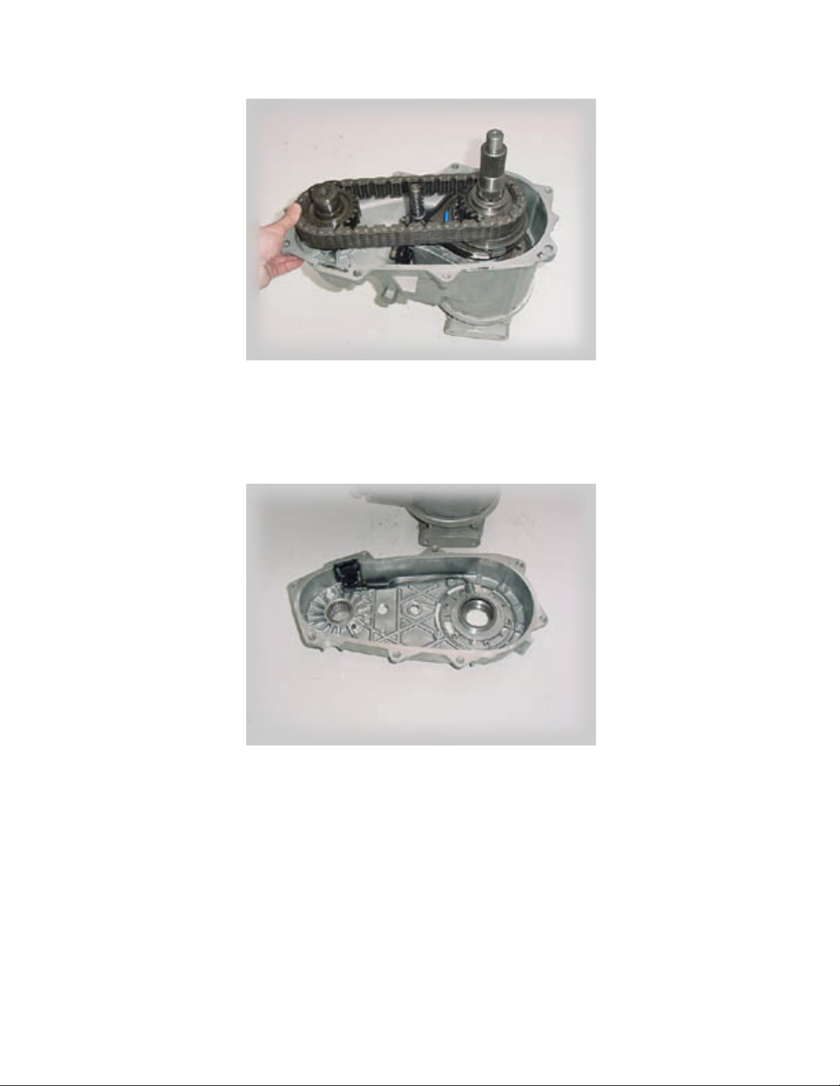
17) Install the mainshaft assembly and mode fork into the case as
shown (Fig.13). The mode fork rod should be well lubricated before
performing this step. The lubricated rod should slide down through the
range fork easily. Install the spring you removed in step 11.
FIG: 13
18) Loop the chain around the main sprocket and front output shaft
then lower the front output shaft through the bearing until it seats
firmly (Fig.14).
Page 9
9
FIG: 14
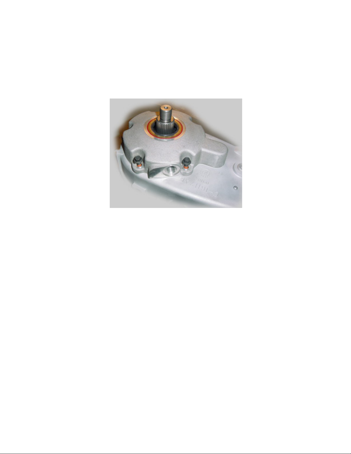
19) Position the pump and pickup tube assembly into the rear case
half as shown (Fig.15).
FIG: 15
20) Install the rear case/pump onto the front case half as shown
(Fig.16a) and installl the 10mm bolts (Fig.16b).
Page 10

10
FIG: 16a
FIG: 16b
21) Place the tone wheel onto the mainshaft as shown (Fig.17). Do not
install the tone wheel in reverse. You will note that at this stage of
assembly, the tone wheel will rest on top of the oil pump. This is not
an issue. Installation of the yoke nut in Step 23 will draw the shaft
upward therefore raising the tone wheel off of the pump surface. You
will also observe that the tone wheel spins freely on the shaft,
however the tone wheel will become stationary upon tightening of the
nut in Step 23.
Page 11
11
FIG: 17
22) Install the new, rear bearing housing into position. Apply a thin
bead of silicone to the back of the housing mounting face and grease
to the seal lip before lowering the housing into place (Fig.18).
FIG: 18
23) Apply a small amount of RTV to the back side of the nut and in the
threads before tightening. Install the 5, 8mm bolts to hold the rear
housing in place. Install the yoke and nut as shown. Torque to 200 lb-
ft. (Fig.19). This kit does not utilize a rubber star washer beneath the
nut.
NOTE: If you experience an erratic speedometer needle, this is an
indication that the nut is insufficiently torqued. Retorque to
recommended amount.
Page 12

12
FIG: 19
24) Install the sensor into the rear housing and fill the case with
Chrysler ATF to complete the installation.
 Loading...