

Page 1

Index Page
English 1
Español 7
Français 13
Deutsch 19
Italiano 25
DIGITAL SOLDERING STATIONS
MD 3050
LD 3100
ID 3110
TD 3120
SD 3140
0415470-3
Page 2
1
We appreciate the confidence you have shown in JBC by purchasing this station.
It has been manufactured with the highest standards of quality to ensure reliable
service. Before starting up the apparatus, we suggest you to read through the
following instructions carefully.
ENGLISH
FEATURES
Stations composition
MD 3050 230V Ref. 3050200:
- Control Unit Ref. 3430200
- 5W soldering iron
with tip R-0 D Ref. 3030000
- Soldering iron stand MS 1300 Ref. 0290130
- Instructions manual Ref. 0415470
LD 3100 230V Ref. 3100200:
- Control Unit Ref. 3130200
- 20W soldering iron
with tip B-05 D Ref. 3000000
- Soldering iron stand LS 1100 Ref. 0290110
- Instructions manual Ref. 0415470
ID 3110 230V Ref. 3110200:
- Control Unit Ref. 3130200
- 50W soldering iron
with tip R-10 D Ref. 3010000
- Soldering iron stand US 1000 Ref. 0290100
- Instructions manual Ref. 0415470
TD 3120 230V Ref. 3120200:
- Control Unit Ref. 3130200
- 60W soldering iron with solder
feed system and tip C-20 D Ref. 3020000
- Soldering iron stand TS 1200 Ref. 0290120
- Instructions manual Ref. 0415470
SD 3140 230V Ref. 3140200:
- Control Unit Ref. 3730200
- 70W soldering iron
with tip T-55 D Ref. 3070000
- Soldering iron stand US 1000 Ref. 0290100
- Instructions manual Ref. 0415470
The 20, 50, 60 and 70W soldering irons may be
connected to Control Unit Ref. 3130200 though
it is recommended to use the 70W soldering
iron with Control Unit Ref. 3730200, which is
specially suited to the power needs of that
soldering iron. This latter control unit can also
be used with all the soldering irons except the
5W one, which needs its own Control Unit Ref.
3430200.
Page 3
2
ENGLISH
Control Unit techical data
1. Safety transformer with mains separator:
LD-ID-TD-SD: 230V/24V 50Hz.
MD: 230V/12V 50Hz.
2. Temperature range: 50°C to 400°C in
one-degree intervals.
3. Programmed temperature accurate to ±3%.
4. Microprocesor with five user-programmable
functions.
5. Keeps all programmed data in store, even
when the appliance is switched off.
6. Digital lecture by LCD display.
7. Abides the CE standards for electrical
security, electromagnetical compatibility
and antistatic protection.
8. Equipotential connector is earth connected to
the plug feed of the station.
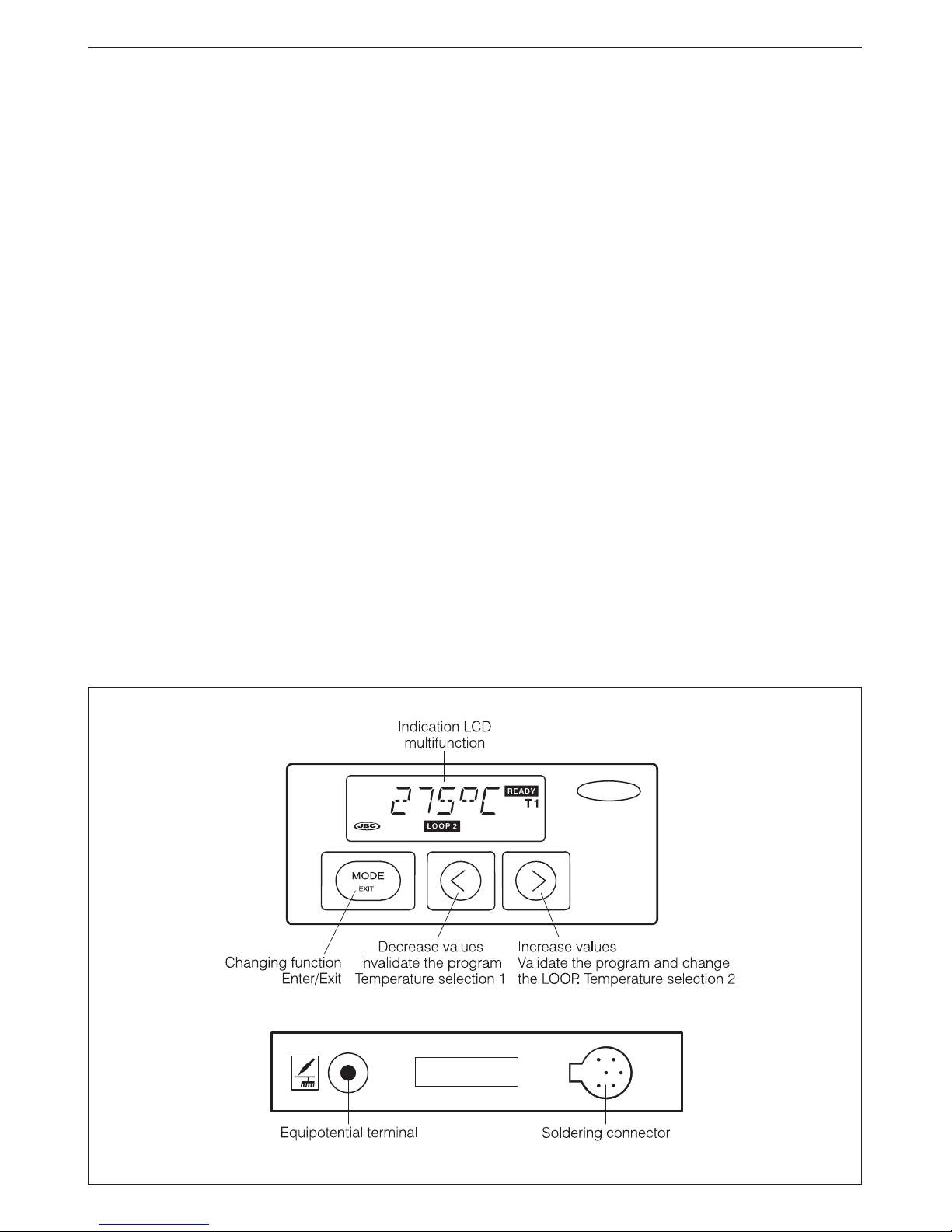
OPERATION
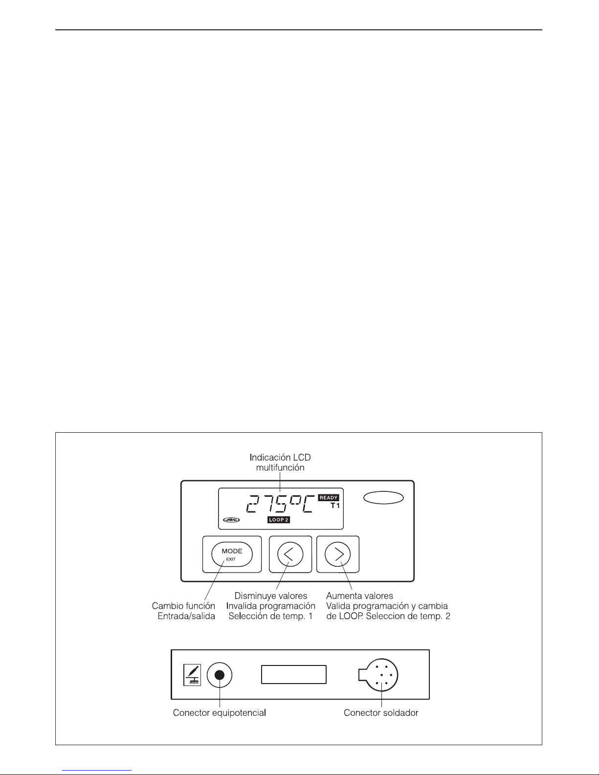
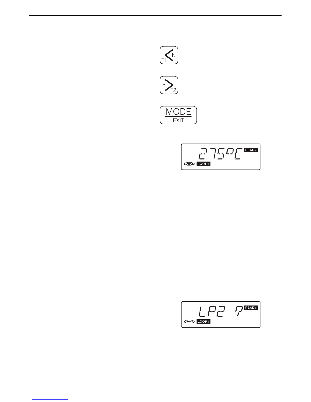
Use of keys
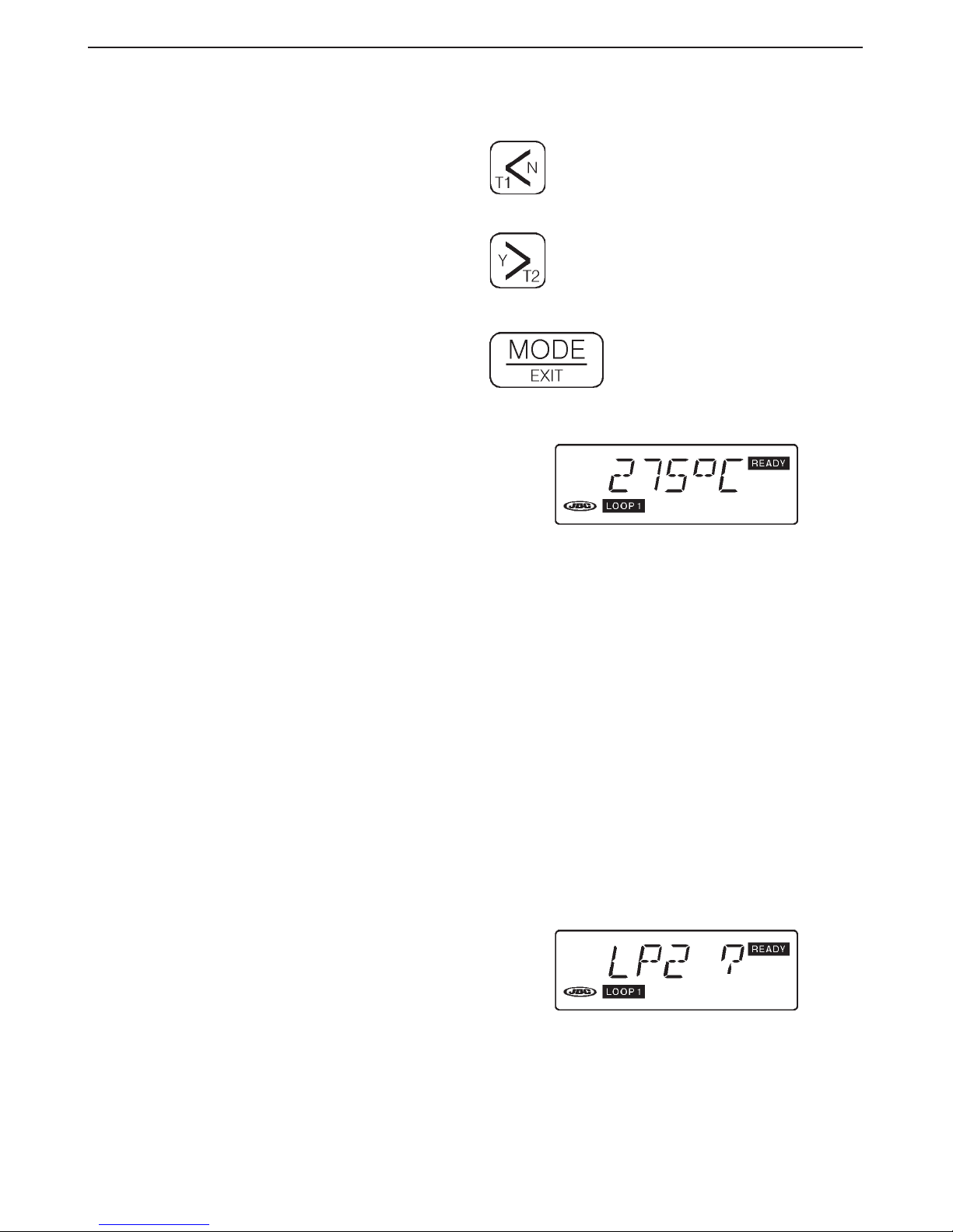
< = Reduces values.
N (No) = Invalidates programming.
T1 = Selection of temperature 1
> = Increases values..
Y (Yes) = Validates programming
and changes LOOP.
T2 = Selection of temperature 2
Switches from one function to
another and programme enter/exit.
Start-up display
When the message READY appears the tip of the
soldering iron will be ± 6°C from the temperature
selected.
WORKING MODES
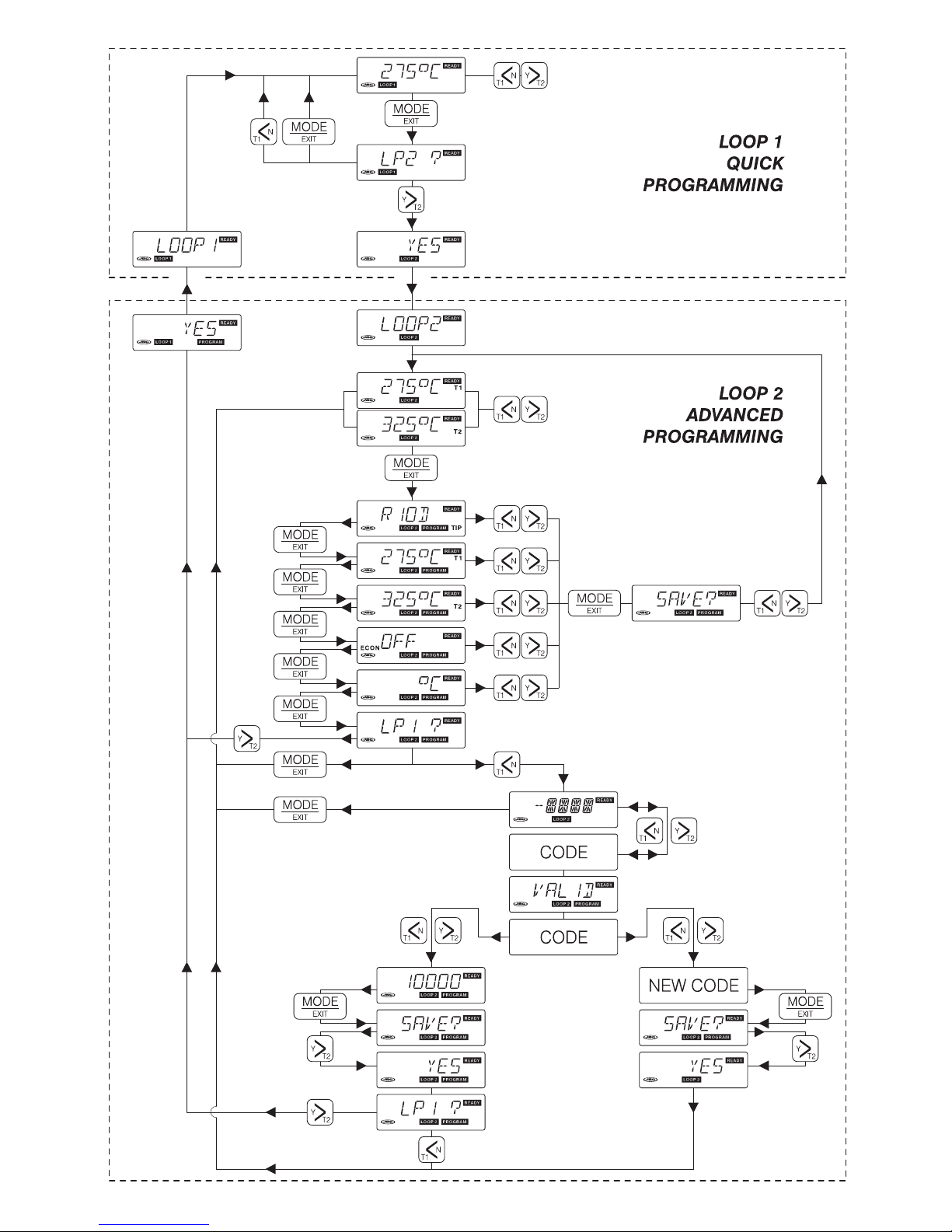
The programme of the circuit has two modes of
operation which we call LOOP 1 and LOOP 2.
LOOP 1
Quick Programming
This mode gives direct access to temperature
changes.
The temperature may be raised or lowered
degree by degree using the < and > keys
and LOOP 2 may be accessed by the MODE
and > keys.
The station is supplied from the works in LOOP 1
and the following tip types are programmed:
Station MD 3050 Tip R- 0 D
" LD 3100 " B-05 D
" ID 3110 " R-10 D
" TD 3120 " C-20D
" SD 3140 " T-55 D
Page 4

3
Page 5
4
ENGLISH
To change the tip model or the °C-°F unit the
data must be programmed in LOOP 2 and
these changes will be taken up in LOOP 1.
LOOP 2
Advanced Programming
Advanced programming system, allowing access
to the 5 functions provided by the system.
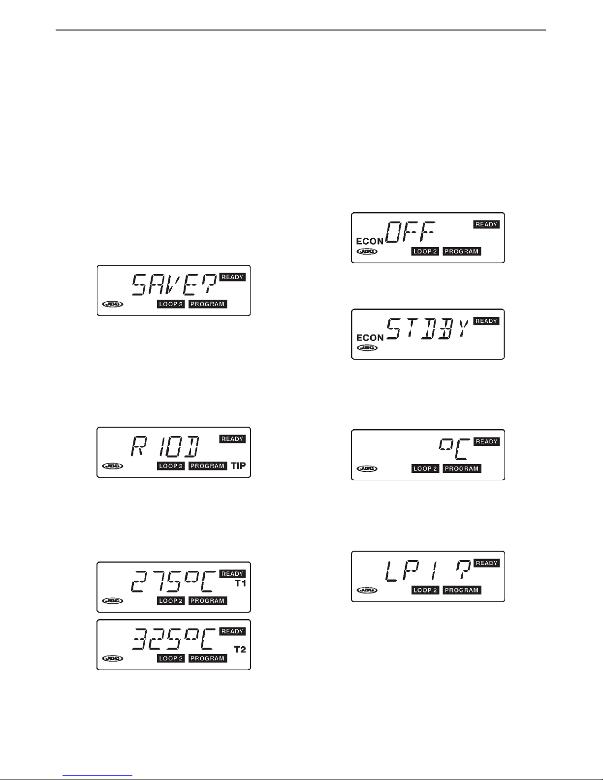
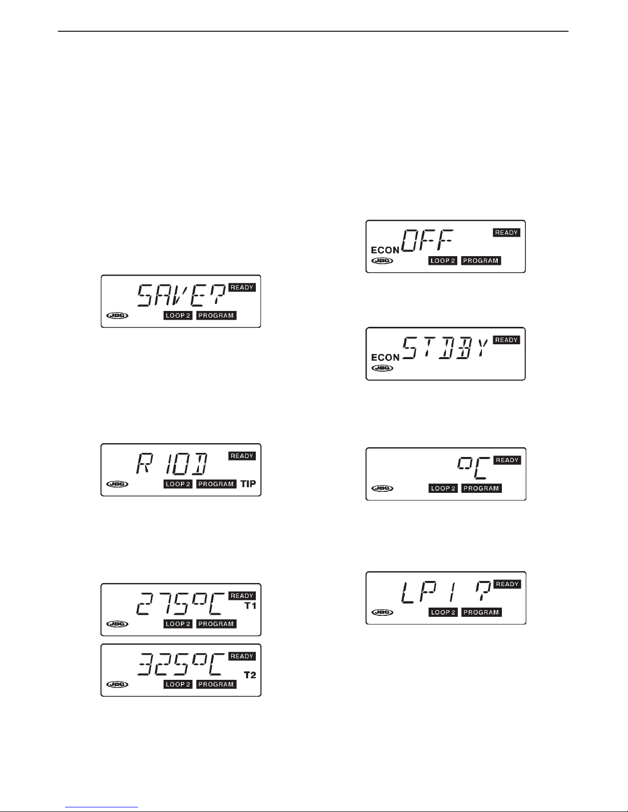
Programming
Press the MODE key as many times as necessary
to reach the function you require. Use the key <
and > to change the value shown. Push the
MODE
key again, and the prompt SAVE? will
appear in the display.
Pressing the > YES key saves the new data,
while pressing the < NO key maintains the
previous data.
Functions
Tip model -TIP-
It shows the tip model selected. If you wish to
change it, use the keys < or >. All the tip models
appear one by one.
Tip temperature -T1- T2-
Two alternative temperatures, T1 and T2, may
be programmed within the 50°C-400°C range.
For fine soldering a low temperature is required,
which can be programmed as T1 while thick
soldering calls for a higher temperature which
can be programmed as T2.
Economizer -ECON-
This function is suitable for repair works or
noncontinuous work where the soldering iron
remains unused for long periods of time.
Lowers the working temperature to 250°C, after
a preselected time of 1 to 99 minutes.
This function helps reducing tin oxidizing and
improves soldering quality results.
The setting programmed at the works is 0
minute, whereby the economizer is inactivated
(OFF message).
When the pre-set time has elapsed, the
message STANDBY appears on the display.
Press any key to return to the working
temperature and to reset the timer.
°C - °F Scale
Choice of units in °C (Celsius)
or °F (Fahrenheit).
Changing the LOOP / access to LOOP 1
Press key > YES if you wish to access LOOP 1,
key < NO to change the access code, or the
MODE
key to stay in LOOP 2 without making
any changes. This screen only appears when
the current access code is 10000.
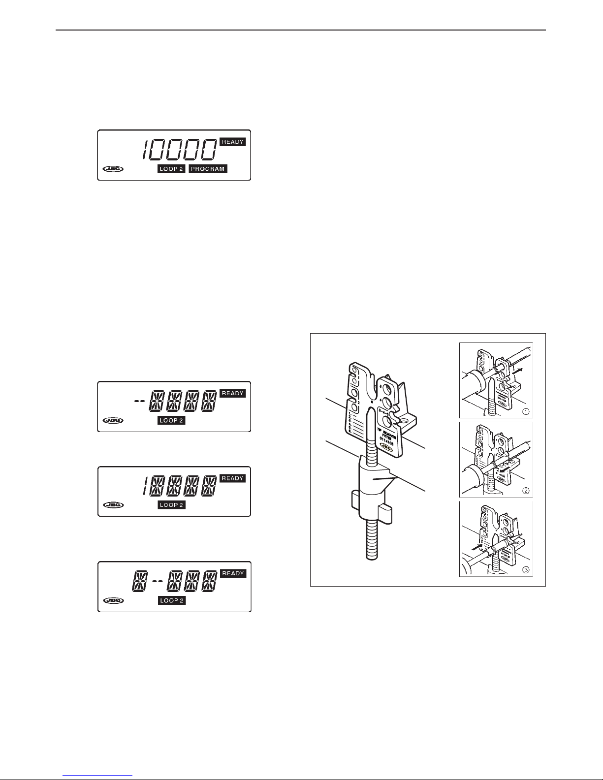
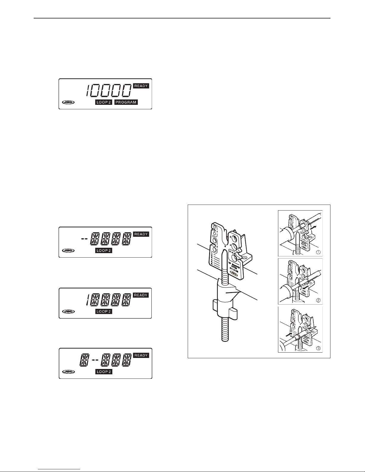
Access code
Using the access code enables the
programmed data to be protected against
change by unauthorized personel.
Page 6
5
ENGLISH
There are two access code categories:
- NO PROTECTION
The code is 10000. It allows to modify all
data and move from one Loop to another.
This code is assigned at source.
- COMPLETE PROTECTION
Numbers between 00001 and 99999
(except 10000). In this category it is
essential to enter the access code before
any data can be modified. Does not allow
access to LOOP 1.
Entering the access code
If you are accessing this display for the first time,
you will first of all have to enter the factoryprogrammed one, i.e. 10000.
1)To enter the figure 1 press < twice.
2)Press > to move the first digit to the right.
3)To enter the first 0 press the < key once, and
so on with the others. Press > to end.
The VALID message which comes up on the
display indicates that the number has been
entered correctly.
Then, the new password may be entered
following the same process.
If an attempt has been made to enter the
password and the number is wrong, it will wink
on the display. To enter the correct password,
push MODE until the enter display appears.
RECOMMENDATIONS FOR USE
For soldering
- The components and the circuit should be
cleaned and degreased.
- Preferably select a temperature below 375°C.
Excess temperature may cause the printed
circuit tracks to break loose.
- The tip must be well tinned for good heat
conduction. If it has been inoperative for any
length of time, it should be retinned.
Soldering iron tip replacement
Use the tip removal device Ref. 0114108.
➀
Remove the ring to release the tip.
➁
Remove the tip by pulling the soldering iron
lengthwise, without forcing the element.
➂
Insert the new tip and make sure that it has
penetrated fully home.
Tip care
- To clean the tips, use the damp sponge
included with the stand.
- Do not file the tips or use abrasive tools
which may damage the tip’s protective
surface coating and avoid knocking them
about.
- If the tip has been a long time without being
tinned, use the metal brush Ref. 0297705
adaptable to the support, to remove any dirt
and oxid.
Page 7
6
TECHNICAL SERVICE
Troubleshooting and solutions
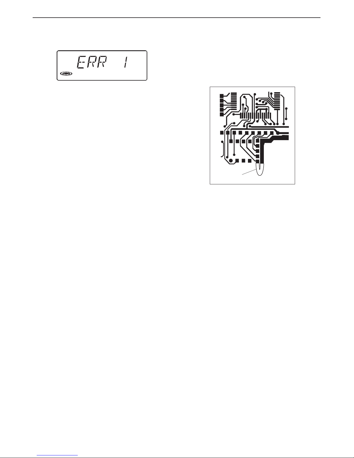
Whenever an ERR message appears, the control
unit switches off completely. To reconnect, use
the main start switch. The following messages will
appear on the display:
- BLANK DISPLAY
Electricity supply failure. Check that the
apparatus is turned on or whether the fuse at
the back of the box (T 315 mA) has blown.
- ERR 1
The temperature does not rise. Possible
causes: heating element fused, heating element
supply cable cut, faulty triac. Check and
replace as required.
- ERR 2
The temperature rises uncontrollably. Possible
causes: crossed Triac.
- ERR 3
There is no thermocouple reading. Possible
causes: the soldering iron is not connected to
the unit, thermocouple open, soldering iron
cord broken.
- ERR 4
Irregular thermocouple readings. Possible
causes: thermocouple or its connections in
bad condition.
- ERR 5
The permanent memory is not functioning.
Information cannot be saved or read. Replace
the whole circuit.
ENGLISH
OFF
CAL
RST
PW
Bridge
JBC reserves the right to change specifications mentioned in
this instructions manual without prior notice.
Cancelling the access code
To carry out this operation, the Control Unit must
be opened and the following operations
performed:
- Solder a bridge between the point marked PW
and the relevant.
- Close the control unit and connect the
apparatus. At this point the previous code is
annulled.
- Disconnect the apparatus, open the Control
Unit, and desolder the bridge.
- You may now introduce a new access code,
after keying in the initial number 10000.
Page 8
7
Agradecemos la confianza depositada en JBC al adquirir esta estación. Ha sido
fabricada con las más estrictas normas de calidad para prestarle el mejor
servicio. Antes de poner en marcha el aparato, recomendamos leer con atención
las instrucciones que a continuación se detallan.
ESPAÑOL
CARACTERISTICAS
Composición de las estaciones
MD 3050 230V Ref. 3050200:
- Unidad de Control Ref. 3430200
- Soldador 5W
con punta R-0 D Ref. 3030000
- Soporte soldador MS 1300 Ref. 0290130
- Manual de instrucciones Ref. 0415470
LD 3100 230V Ref. 3100200:
- Unidad de Control Ref. 3130200
- Soldador 20W
con punta B-05 D Ref. 3000000
- Soporte soldador LS 1100 Ref. 0290110
- Manual de instrucciones Ref. 0415470
ID 3110 230V Ref. 3110200:
- Unidad de Control Ref. 3130200
- Soldador 50W
con punta R-10 D Ref. 3010000
- Soporte soldador US 1000 Ref. 0290100
- Manual de instrucciones Ref. 0415470
TD 3120 230V Ref. 3120200:
- Unidad de Control Ref. 3130200
- Soldador con aportación de
estaño 60W y punta C-20 D Ref. 3120000
- Soporte soldador TS 1200 Ref. 0290120
- Manual de instrucciones Ref. 0415470
SD 3140 230V Ref. 3140200:
- Unidad de Control Ref. 3730200
- Soldador 70W
con punta T-55 D Ref. 3070000
- Soporte soldador US 1000 Ref. 0290100
- Manual de instrucciones Ref. 0415470
A la Unidad de Control Ref. 3130200 se pueden
conectar los soldadores de 20, 50, 60 y 70W,
aunque este ultimo se recomienda utilizarlo con
la Unidad de Control Ref. 3730200, adaptada
especialmente a las necesidades de potencia de
este soldador. A esta unidad también se le pueden
conectar todos los soldadores exceptuando el de
5W que requiere su propia Unidad de Control
Ref. 3430200.
Page 9
8
Datos técnicos de la Unidad de Control
1. Transformador de seguridad separador de red:
LD-ID-TD-SD: 230V/24V 50Hz.
MD: 230V/12V 50Hz.
2. Selección de temperatura entre: 50°C y 400°C
en intervalos de un grado.
3. Precisión de la temperatura programada: ±3%.
4. Microprocesador con 5 funciones
programables por el usuario.
5. Conservación de todos los datos
programados, incluso con el aparato
desconectado.
6. Lectura digital por display LCD.
7. Cumple la normativa CE sobre seguridad
eléctrica, compatibilidad electromagnética y
protección antiestática.
8. El conector equipotencial está conectado a la
toma de tierra de la clavija de la estación.
ESPAÑOL
FUNCIONAMIENTO
Utilidad de las teclas
< = Disminuye valores.
N (No) = Invalida programación.
T1 = Selección de temperatura 1
> = Aumenta valores.
Y (Yes) = Valida programación y
cambia de LOOP.
T2 = Selección de temperatura 2
Pasar de una función a otra y
entrar/salir de programación.
Pantalla inicial
Cuando aparezca el mensaje READY (listo) la
punta del soldador estará a ± 6°C de la
temperatura seleccionada.
MODOS DE TRABAJO
El programa del circuito dispone de dos modos de
trabajo que llamamos LOOP 1 y LOOP 2.
LOOP 1
Quick Programming
(Programación rápida):
En este modo se accede directamente al cambio
de temperatura.
Por medio de las teclas < y > se disminuye
o aumenta la temperatura y se puede pasar
al LOOP 2 por medio de las teclas MODE
y > YES.
La estación sale de fábrica en este LOOP 1 y
están programados los siguientes tipos de
punta:
Estación MD 3050 punta R- 0 D
" LD 3100 " B-05 D
" ID 3110 " R-10 D
" TD 3120 " C-20 D
" SD 3140 " T-55 D
Page 10
9
Page 11
10
ESPAÑOL
Para cambiar el modelo de punta o la unidad °C-°F
se deben programar en el LOOP 2, estos cambios
quedarán asumidos en el LOOP 1.
LOOP 2
Advanced Programming
(Programación avanzada):
Sistema de programación avanzado, con el que se
accede a las 5 funciones que permite el sistema.
Programación
Pulse la tecla MODE las veces necesarias hasta
llegar a la función que desee. Cambie por medio
de las teclas < y > el valor que precise. Pulse de
nuevo MODE
y en el display aparecerá SAVE?
(guardar ?).
Con la tecla > YES se guardan los nuevos
datos, y con la tecla < NO, se mantienen los
anteriores.
Funciones programables
Tipo de punta -TIP-
Muestra el modelo de punta seleccionado. Si desea
cambiarlo, utilice las teclas < o >. Aparecerán
sucesivamente todos los modelos de punta.
Temperatura de la punta -T1- T2-
Se pueden programar dos valores de temperatura
alternativos T1 y T2, comprendidos entre 50 °C y
400 °C. En T1 se recomienda seleccionar
temperaturas bajas para soldaduras finas, y en T2
altas, para soldaduras gruesas. Se cambia T1-T2
por medio de < o >.
Economizador -ECON-
Esta función sirve para trabajos de reparación o
discontínuos, en los que el soldador está largos
períodos de tiempo sin utilizar.
Reduce la temperatura de trabajo a 250 °C, una
vez transcurrido el tiempo seleccionado entre 1 y
99 minutos.
Con esta función se reduce la oxidación del estaño
y las soldaduras son de mejor calidad.
El valor programado en origen es 0 minutos, con
lo que el economizador permanece inactivo
(mensaje OFF).
Cuando haya transcurrido el tiempo seleccionado
aparecerá en pantalla STANDBY (estado de
espera).
Pulse cualquier tecla para volver a la temperatura
de trabajo.
Unidad -°C - °F-
Selección de las unidades
°C (Celsius) o °F (Fahrenheit).
Cambio de LOOP/Acceso al LOOP1
Pulse la tecla > YES si desea acceder al LOOP 1,
la tecla < NO para modificar la clave de acceso, o
la tecla MODE para permanecer en el LOOP 2 sin
realizar ninguna modificación. Esta pantalla aparece
solamente cuando la clave de acceso actual es la
10000.
Clave de acceso
Si se utiliza, permite proteger los datos
programados, impidiendo su modificación por
persona no autorizada.
Page 12
11
ESPAÑOL
Hay dos categorías de clave de acceso:
- SIN PROTECCIÓN
La clave es 10000. Permite modificar todos
los datos y pasar de un Loop a otro. Esta es
la clave asignada en origen.
- PROTECCIÓN COMPLETA
Números comprendidos entre 00001 y 99999
(excepto el 10000). Es indispensable en esta
categoría introducir la clave de acceso para
modificar cualquier dato. No permite acceder
al LOOP1.
Introducción de la clave de acceso
Si accede a esta pantalla por primera vez, es
necesario introducir primero la clave de origen,
es decir 10000.
1) Para introducir el 1 pulse dos veces <.
2) Para desplazar el primer dígito a la derecha
pulse >.
3) Para introducir el primer 0 pulse una vez < y así
sucesivamente.
Pulse > para finalizar.
El mensaje VALID indica que el número ha sido
correcto. Entonces y siguiendo el mismo proceso,
podrá entrar la nueva clave.
Si ha intentado introducir la clave y el número es
erróneo, aparecerá en la pantalla haciendo
intermitencias.
Para volver a introducir la clave correcta, pulse
MODE hasta regresar a la pantalla de
introducción.
RECOMENDACIONES DE USO
Para soldar
- Los componentes y el circuito deben estar
limpios y desengrasados.
- Con preferencia seleccione una temperatura
inferior a 375°C. El exceso de temperatura
puede provocar el desprendimiento de las
pistas del circuito impreso.
- La punta debe estar bien estañada para
conducir bien el calor. Si permanece mucho
tiempo en reposo, estáñela de nuevo.
Cambio de punta del soldador
Utilice el extractor de puntas Ref. 0114108.
➀
Retire la anilla para liberar la punta.
➁
Extraiga la punta tirando del soldador, en
sentido longitudinal y sin forzar la resistencia.
➂
Introduzca la nueva punta y asegúrese de
que ha penetrado a fondo.
Conservación de las puntas
- Para la limpieza de las puntas utilice la
esponja húmeda que lleva el soporte.
- No lime ni utilice herramientas abrasivas que
puedan destruir la capa de protección
superficial de la punta y evite los golpes.
- Si la punta ha estado mucho tiempo sin
ser estañada, utilice el cepillo metálico
Ref. 0297705 adaptable al soporte, para
eliminar el óxido y la suciedad.
Page 13

12
ESPAÑOL
JBC se reserva el derecho de introducir variaciones técnicas
sin previo aviso.
Anulación de la clave de acceso
Para realizar esta operación, es preciso abrir la
Unidad de Control y realizar las operaciones que
a continuación se indican:
- Haga un puente con soldadura entre el punto
marcado PW y el común.
SERVICIO TECNICO
Anomalías y solución
Siempre que aparece un mensaje de error ERR
la Unidad de Control se desconecta por completo.
Para volver a conectar accionar el interruptor
general de puesta en marcha. Posibles mensajes
que puedan aparecer en la pantalla:
- PANTALLA EN BLANCO
Falla la alimentación. Compruebe que está
conectado el aparato. Puede estar fundido el
fusible situado en la parte posterior de la caja
(T 315 mA).
- ERR 1
La temperatura no aumenta. Causas posibles:
resistencia calefactora abierta, cable
alimentación del calefactor cortado, triac
defectuoso. Verificar y cambiar lo que proceda.
- ERR 2
La temperatura aumenta sin control. Causas
posibles: Triac cruzado.
- ERR 3
No hay lectura del termopar. Causas posibles:
no tener conectado el soldador a la unidad,
termopar abierto, cable del soldador roto, etc.
- ERR 4
Lecturas del termopar irregulares. Causas
posibles: termopar o sus conexiones en mal
estado.
- ERR 5
La memoria permanente no funciona. No se
ha podido grabar o leer información. Cambiar
el circuito completo.
Bridge
- Cierre la Unidad de Control y conecte el
aparato. En este momento queda anulada la
clave anterior.
- Desconecte el aparato, abra la Unidad de
Control y desuelde el puente.
- Ahora podrá introducir una nueva clave de
acceso, entrando previamente el número inicial
10000.
OFF
CAL
RST
PW
Page 14

13
Nous vous remercions pour la confiance placée dans JBC lors de l'acquisition de
cette station. Elle a été réalisée avec des hautes performances, avec les plus
strictes normes de qualité. Avant de mettre l'appareil en marche, nous vous
conseillons de lire attentivement les instructions qui sont détaillées ci-dessous.
FRANÇAIS
CARACTERISTIQUES
Composition des stations
MD 3050 230V Réf. 3050200:
- Unité de Contrôle Réf. 3430200
- Fer à souder 5W
avec panne R-0 D Réf. 3030000
- Support fer à souder MS 1300 Réf. 0290130
- Manuel d’instructions Réf. 0415470
LD 3100 230V Réf. 3100200:
- Unité de Contrôle Réf. 3130200
- Fer à souder 20W
avec panne B-05 D Réf. 3000000
- Support fer à souder LS 1100 Réf. 0290110
- Manuel d’instructions Réf. 0415470
ID 3110 230V Réf. 3110200:
- Unité de Contrôle Réf. 3130200
- Fer à souder 50W
avec panne R-10 D Réf. 3010000
- Support fer à souder US 1000 Réf. 0290100
- Manuel d’instructions Réf. 0415470
TD 3120 230V Réf. 3120200:
- Unité de Contrôle Réf. 3130200
- Fer à souder avec apport
d’étain 60W et panne C-20 D Réf. 3020000
- Support fer à souder TS 1200 Réf. 0290120
- Manuel d’instructions Réf. 0415470
SD 3140 230V Réf. 3140200:
- Unité de Contrôle Réf. 3730200
- Fer à souder 70W
avec panne T-55 D Réf. 3070000
- Support fer à souder US 1000 Réf. 0290100
- Manuel d’instructions Réf. 0415470
Sur le Unité de Contrôle Réf 3130200 il est possible
de connecter les fers à souder 20, 50, 60 et 70W,
bien qu'il soit conseillé d'utiliser ce dernier avec
l'Unité de Contrôle Réf. 3730200, spécialement
adaptée aux besoins en puissance de ce fer. Sur
cette dernière unité de contrôle on peut également
connecter tous les fers à souder à l'exception du
5W qui recquière sa propre Unité de Contrôle
Réf. 3430200.
Page 15

14
Données techniques de l'Unité de Contrôle
1. Transformateur de sécurité séparateur du
réseau: LD-ID-TD-SD: 230V/24V 50Hz.
MD: 230V/12V 50Hz.
2. Sélection de température entre: 50°C et 400°C
par intervalles de 1 degré.
3. Précision de la température programmée: ±3%
4. Microprocesseur avec cinq fonctions
programmables par l’utilisateur.
5. Sauvegarde de toutes les données
programmées, même si l'apparéil est
débranché.
6. Lecture digitale sur écran LCD.
7. Elle est conforme aux normes CE pour la
sécurité électrique, la compatibilité électromagnétique et la protection antistatique.
8. La prise équipotentielle est connecté à la prise
de terre de la fiche d'alimentation de la station.
FRANÇAIS
FONCTIONNEMENT
Utilité des touches
< = Diminue valeurs.
N (No) = Annule programmation.
T1 = Sélection de temperature 1
> = Augmente valeurs.
Y (Yes) = Valide programmation et
modifie le LOOP.
T2 = Sélection de temperature 2
Passer d’une fonction à une autre
et entrer/sortir de programmation.
Écran initial
Lorsque apparaît le message READY (prêt) la
panne du fer à souder sera à ± 6°C de la
température sélectionnée.
MODES DE TRAVAIL
Le programme du circuit dispose de deux modes
de fonctionnement que nous appelons LOOP 1 et
LOOP 2.
LOOP 1
Quick Programming
(Programmation rapide):
Ce mode permet d’accéder directement à la
fonction Modification de température.
A l’aide des touches < e > , on diminue ou on
augmente la température de degré en degré.
Les touches MODE et > YES permettent de
passer au LOOP 2.
A sa sortie d’usine, la station est programmée en
LOOP 1 et pour les types de panne suivants:
Station MD 3050 Panne R- 0 D
" LD 3100 " B-05 D
" ID 3110 " R-10 D
" TD 3120 " C-20 D
" SD 3140 " T-55 D
Page 16

15
Page 17

16
FRANÇAIS
Pour modifier le modèle de panne ou l’unité °C-°F,
introduire les modifications dans le LOOP 2. Elles
seront automatiquement prises en compte par le
LOOP 1.
LOOP 2
Advanced Programming
(Programmation avancée):
Système de programmation ultra-moderne
permettant d’accéder aux 5 fonctions réalisées par
le système.
Programmation
Appuyez sur la touche MODE autant de fois que
nécessaire pour parvenir à la fonction désirée.
Modifiez la valeur choisie à l’aide des touches <
et >. Appuyez de nouveau sur MODE, l’écran
affichera SAVE? (sauvegarder?).
La touche > YES permet de sauvegarder les
nouvelles données; avec < NO, on conserve les
données antérieures.
Fonctions programmables
Modèle de panne -TIP-
Signale le modèle de panne sélectionné. Si vous
souhaitez le modifier, utilisez les touches < ou >.
Tous les modèles de panne apparaîtront
successivement sur l’écran.
Température de la panne -T1- T2-
On peut programmer deux valeurs de température
alternatives T1 et T2, comprises entre 50 °C et
400 °C. En T1, nous vous recommandons de
sélectionner des températures basses pour les
soudures fines. En T2, vous les sélectionnerez
élevées pour les soudures épaisses.
Economiseur -ECON-
Cette fonction sert pour les travaux de réparation
ou les travaux discontinus, au cours desquels le
fer à souder reste de longs moments sans l'utiliser.
Réduit la température de travail à 250 °C, lorsque
le temps programmé (de 1 à 99 minutes) s’est
écoulé.
Avec cette fonction, il est possible de réduire
l'oxydation de l'étain et les soudures sont de
meilleure qualité.
La valeur programmée en usine est de 0 minutes;
l’économisateur reste donc inactif (message OFF).
Lorsque le temps sélectionné s’est écoulé, il
apparaîtra sur l’écran STANDBY (état
d’attente).
En pressant n’importe quelle touche, on revient à
la température de travail.
Unité -°C - °F-
Sélection des unités °C (Celsius)
ou °F (Fahrenheit).
Change de LOOP/Accès au LOOP 1
Appuyer sur > YES pour passer en LOOP 1,
sur < NO pour modifier la clé d’accès, ou sur
MODE pour rester en LOOP 2 sans introduire
de modifications. Cet écran n’apparaît que
lorsque la clé d’accès est 10000.
Code d'accès
L'utilisation de la clé d'accès permet de
protéger les données programmées, en
empêchant leur modification par des personnes
non autorisées.
Page 18

17
Il y a deux catégories de clé d'accès:
- SANS PROTECTION
Le code est 10000. Il permet de modifier
toutes les données et passer d'un Loop à un
autre. C'est la clé programmée à l'origine.
- PROTECTION COMPLETE
Numéros compris entre 00001 et 99999
(excepté le 10000). Il est indispensable dans
cette catégorie d’introduire le code d’accès
pour modifier n’importe quelle donnée. Ne
permet d’accéder au LOOP1.
Introduction du code d’accès
Si vous accédez à cet écran pour la première
fois, il est nécessaire d’introduire tout d’abord
celui mémorisé à l’origine, c’est à dire 10000.
1) Pour introduire le 1, pressez deux fois <.
2)Pour déplacer le premier chiffre vers la droite,
pressez >.
3) Pour introduire le premier 0, appuyer une fois sur
<, et ainsi de suite. Appuyer sur > pour terminer.
Le message VALID qui apparaît à l’écran, indique
que l’opération d’entrée du numéro a été correcte.
Ensuite, en suivant le même procédé, vous
pourrez introduire la nouvelle clé.
Vous avez essayé d’introduire la clé, mais le
numéro est erroné: il apparaît sur l’écran par
intermittence. Pour introduire la bonne clé,
appuyez sur MODE jusqu’à ce que la fenêtre
Introduction réapparaisse sur l’écran.
FRANÇAIS
RECOMMANDATIONS D’UTILISATION
Pour souder
- Les composants et le circuit doivent être
propres et dégraissés.
- De préférence choisir une température
inférieure à 375°C. L’excès de température
peut provoquer le décollement des pistes du
circuit imprimé.
- La panne doit être bien étamée pour bien
conduire la chaleur. Lorsqu’elle est restée
longtemps au repos, l’étamer à nouveau.
Changement de la panne du fer à souder
Utilisez l’extracteur de pannes. Réf. 0114108.
➀
Retirez l’anneau pour libérer la panne.
➁
Extraire la panne en tirant légèrement le fer à
souder, afin de ne pas endommager la
résistance.
➂
Introduire la nouvelle panne et assurez-vous
qu'elle soit enfoncée jusqu’au bout.
Conservation des pannes
- Pour le nettoyage des pannes, utilisez
l’éponge humide que contient le support.
- Ne limez ni n’utilisez aucun outil abrasif qui
pourrait détruire la couche de protection
superficielle de la panne et evitez les coups.
- Si la panne n'a pas été étamée depuis
longtemps, nettoyez-la à l'aide de la brosse
métallique Réf. 0297705.
Page 19

18
FRANÇAIS
JBC se réserve le droit d'introduire des variations techniques
ou de conception sans préavis.
SERVICE TECHNIQUE
Anomalies et solution
Chaque fois qu’il apparaît un message d’erreur
ERR, l’Unité de Contrôle se débranche
complètement Pour la brancher à nouveau,
actionnez l’interrupteur général de mise en
marche. Les messages suivants poivent
apparaître à l’écran :
- ECRAN BLANC
Panne d’alimentation. Vérifiez que l'apparéil
est connecté et si le fusible situé dans la
partie postérieure du boîtier n’est pas fondu
(T 315 mA).
- ERR 1
La température n'augmente pas ou le débit
d'air est très bas. Causes possibles :
résistance chauffage ouverte, câble
d'alimentation du chauffage coupé, triac
défectueux. Vérifiez et changez ce qu’il
convient.
- ERR 2
La température augmente sans contrôle.
Causes possibles : Triac croisé.
- ERR 3
Absence de lecture du thermocouple. Causes
possibles: le fer à souder n’est pas branché
à l'Unité, thermocouple ouvert, câble de
connexion du thermocouple cassé.
- ERR 4
Lectures du thermocouple irrégulières. Causes
possibles: thermocouple ou ses connexions
en mauvais état.
- ERR 5
La mémoire permanente ne fonctionne pas.
On n'a pas pu enregistrer ou lire l'information.
Changer le circuit complet.
Annulation du code d’accès
Pour réaliser cette opération, il faut ouvrir l’Unité
de Contrôle et suivre les indications suivantes:
- Faites un pont de soudure entre le point
marqué PW et le point commun.
- Fermez l’Unité de Contrôle et branchez
l’appareil. La clé antérieure est désormais
annulée.
- Débranchez l’appareil, ouvrez l’Unité de
Contrôle et dessoudez le pont.
- Vous pouvez à présent introduire une nouvelle
clé d’accès, après avoir introduit le numéro
initial 10000.
OFF
CAL
RST
PW
Bridge
Page 20

19
Wir danken Ihnen für das JBC mit dem Kauf dieser Station erwiesene Vertrauen.
Er ist mit den strengsten Qualitätsmaßstäben hergestellt, so daß Sie optimale
Lötergebnisse erwarten dürfen. Vor Inbetriebnahme des Geräts lesen Sie bitte
die vorliegende Betriebsanleitung aufmerksam durch.
DEUTSCH
TECHNISCHE MERKMALE
Aufbau der Stationen
MD 3050 230V Art.-Nr. 3050200:
- Steuereinheit Art.-Nr. 3430200
- Lötkolben 5W mit
Spitze R-0 D Art.-Nr. 3030000
- Entlötständer MS 1300 Art.-Nr. 0290130
- Betriebsanleitungen Art.-Nr. 0415470
LD 3100 230V Art.-Nr. 3100200:
- Steuereinheit Art.-Nr. 3130200
- Lötkolben 20W mit
Spitze B-05 D Art.-Nr. 3000000
- Entlötständer LS 1100 Art.-Nr. 0290110
- Betriebsanleitungen Art.-Nr. 0415470
ID 3110 230V Art.-Nr. 3110200:
- Steuereinheit Art.-Nr. 3130200
- Lötkolben 50W mit
Spitze R-10 D Art.-Nr. 3010000
- Entlötständer US 1000 Art.-Nr. 0290100
- Betriebsanleitungen Art.-Nr. 0415470
TD 3120 230V Art.-Nr. 3120200:
- Steuereinheit Art.-Nr. 3130200
- Lötkolben mit Zinnzufhur
60W mit Spitze C-20 D Art.-Nr. 3020000
- Entlötständer TS 1200 Art.-Nr. 0290120
- Betriebsanleitungen Art.-Nr. 0415470
SD 3140 230V Art.-Nr. 3140200:
- Steuereinheit Art.-Nr. 3730200
- Lötkolben 70W mit
Spitze T-55 D Art.-Nr. 3070000
- Entlötständer US 1000 Art.-Nr. 0290100
- Betriebsanleitungen Art.-Nr. 0415470
An die Steuereinheit Art.-.Nr. 3130200 können die
Lötkolben der Leistungen 20 W, 50 W, 60 W und
70 W angeschlossen werden; wir empfehlen jedoch,
letzteren nur mit der Steuereinheit Art.-Nr. 3730200
einzusetzen, die speziell für die Leistungsaufnahme
dieses Kolbens ausgelegt ist. An diese Steuereinheit
können auch alle anderen Lötkolben angeschlossen
werden, mit Ausnahme des 5-W-Kolbens, der seine
eigene Steuereinheit Art.-Nr. 3430200 benötigt.
Page 21

20
Technische Angaben
1. Sicherheitstransformator mit Netztrennung:
LD-ID-TD-SD: 230V/24V 50Hz.
MD: 230V/12V 50Hz.
2. Temperaturwahl zwischen: 50°C und 400°C
und kann in Schritten von 1°C variiert werden.
3. Genauigkeit der eingestellten Temp.: ± 3%
4. Microprocessor mit 5 programmierbaren
Funktionen.
5. Bewahrt alle programmierte Daten auf, auch
wenn abgeschaltet.
6. Digital an-zeige auf LCD-Display ablesbar.
7. Erfüllt die Sicherheitsvorschriften der CE über
elektrische Sicherheit, elektromagnetische
Kompatibilität und antistatischer Schutz.
8. Die Equipotentialausgleichsbuchse ist mit der
Erdung des Netzsteckers verbunden.
DEUTSCH
BETRIEB
Zweck der Tasten
< = Verringerung der Werte.
N (No) = Programmierung außer Kraft.
T1 = Temperaturwahl 1
> = Erhöhung der Werte.
Y (Yes) = Programmierung in Kraft
und LOOP-Wechsel.
T2 = Temperaturwahl 2
Übergang von einer Funktion
zur anderen; Beginn/Ende
Programmierung.
Anfangsanzeige
Wenn im Display die Anzeige READY
(betriebsbereit) erscheint, hat sich die Spitze auf
den vorgewählten Wert (mit einer Toleranz von
± 6°C) erwärmt.
ARBEITSREGIMES
Das Programm des Schaltkreises bietet zwei
Funktionsweisen, die wir LOOP 1 und LOOP 2
(Schleife) nennen.
LOOP 1
Quick Programming
(Schnellprogrammierung):
In diesem Regime hat man direkten Zugang zur
Funktion Temperaturänderung.
Die Tasten < und > erlauben eine gradweise
Verringerung bzw. Erhöhung der Temperatur;
anhand der Tasten MODE und > YES erfolgt
der Übergang zu LOOP 2.
Die Station ist werksmäßig auf LOOP 1 und
folgende Spitzenmodelle programmiert:
Station MD 3050 Spitze R- 0 D
" LD 3100 " B-05 D
" ID 3110 " R-10 D
" TD 3120 " C-20 D
" SD 3140 " T-55 D
Page 22

21
Page 23

22
DEUTSCH
Das Wechseln der Lötspitze bzw. die Umstellung
von °C auf °F wird in LOOP 2 eingegeben. Diese
Veränderungen werden automatisch auch auf
LOOP 1 umgesetzt.
LOOP 2
Advanced Programming
(Programmierung für Fortgeschrittene):
Fortgeschrittenes Programmiersystem, das direkt
auf die fünf verfügbaren Funktionen des Systems
zugreift.
Programmierung
Wiederholt die Taste MODE drücken, bis die
gewünschte Funktion angezeigt wird. Anhand der
Tasten < und > den gewünschten Wert einstellen.
Anschließend erneut die Taste MODE
betätigen;
daraufhin erscheint im Display die Anzeige SAVE?
(Speichern?).
Anhand der Taste > YES können die neu
eingegebenen Parameter abgespeichert werden,
während bei Betätigung der Taste < NO die
bisherigen beibehalten werden.
Programmierbare Menüs
Spitzenmodell -TIP-
Zeigt die gewählte Lötspitze an. Wenn Sie die
Lötspitze auswechseln wollen, drücken Sie die
Tasten < oder >. Es erscheinen der Reihe nach
alle Lötspitzentypen.
Spitzentemperatur -T1- T2-
Es können zwei alternative Werte T1 und T2
zwischen 50 °C und 400 °C programmiert werden.
Es wird empfohlen, in T1 niedrige Temperaturwerte
für feine Lötarbeiten einzugeben, in T2 dagegen
hohe Temperaturwerte für gröbere Lötarbeiten.
Sparfunktion -ECON-
Diese Funktion dient für Wartung- oder
diskontinuierliche Arbeiten, bei denen der Lötkolben
über längere Zeiträume nicht gebraucht wird Setzt
nach Ablauf des vorgewählten Zeitraums (1 bis 99
Minuten) die Arbeitstemperatur auf 250°C herab.
Mit dieser Funktion wird die Oxydierung des Zinns
verringert, womit die Lötungen von besserer
Qualität sind.
Werksmäßig sind 0 Minuten eingestellt, so daß
die Sparfunktion nicht aktiviert ist (Stellung OFF).
Nach Ablauf der voreingestellten Arbeitszeit weist
die Anzeige STANDBY (Stand-by).
Bei Betätigen einer beliebigen Taste wird die
Station in Betrieb genommen.
Einheit -°C - °F-
Wahl der Einheiten °C (Celsius)
oder °F (Fahrenheit).
LOOP-Wechsel / Übergang zu LOOP 1
Wenn Sie zu LOOP 1 übergehen möchten, drücken
Sie bitte die Taste > YES. Bei Drücken der Taste
< NO können Sie das Password verändern, und
bei Betätigen der Taste MODE bleiben Sie in
LOOP 2, ohne Parameter zu verändern. Diese
Anzeige erscheint nur, wenn das gültige
Password 10000 lautet.
Password
Die Verwendung eines Password bietet Ihnen die
Möglichkeit, die eingegebenen Daten vor einer
Veränderung durch nicht befugte Personen zu
schützen.
Page 24

23
Bezüglich des Password gibt es zwei Kategorien:
- OHNE SCHUTZ
Der Sperrcode lautet 10000. Alle Daten können
modifiziert werden. Übergang von einem Loop
zur anderen. Dieses ist den werkseitig
eingegebene Password.
- KOMPLETTE SCHUTZ
Alle Zahlenkombinationen zwischen 00001 und
99999 (außer 10000). Hier bedarf jede
Modifizierung einer vorherigen Eingabe des
Sperrcodes. Gestattet nicht den Zugriff auf
LOOP1.
Eingabe des Sperrcodes
Wird diese Anzeige zur Abänderung des
Sperrcodes zum ersten Mal aufgerufen, muß
zunächst das werkseitig eingestellte Password
10000 eingegeben werden.
1) Zur Eingabe von 1 < zweimal drücken.
2) Zum Übergang auf die nächste Stelle nach
rechts > drücken.
3) Zur Eingabe der ersten 0 drücken Sie bitte
einmal die Taste <, und so fort. Zum Abschluß
Taste > drücken.
Die Anzeige VALID bestätigt, daß die
Zahlenkombination korrekt eingegeben wurde.
Anschließend kann auf die gleiche Weise ein
neues Password eingegeben werden.
Bei Eingabe eines falschen Passwords erscheint
dieses blinkend auf dem Display. Zur erneuten
Eingabe der Zahlenkombination ist die Taste
MODE zu drücken, bis das Display wieder in
Eingabeposition ist.
DEUTSCH
EMPFEHLUNGEN FÜR DEN GEBRAUCH
Zum Löten
- Komponenten und Leiterplatte müssen sauber
und entfettet sein.
- Möglichst immer mit Temperaturen unter
375°C arbeiten. Höhere Temperaturen können
ein Ablösen der Leitungsbahnen zur Folge
haben.
- Wurde der Entlötkolben während einer
längeren Zeit nicht gebraucht, ist er erneut
zu verzinnen.
Spitzenwechsel Lötkolben
Hierzu Spitzenabzieher Art.-Nr. 0114108
verwenden.
➀
Lötspitze durch Abziehen des Rings lösen.
➁
Spitze durch Wegziehen des Lötkolbens
herausnehmen.
➂
Ordnungsgemäßen Sitz der neuen Spitze
überprüfen.
Behandlung der Spitzen
- Spitzen nur mit dem im Kolbenständer
vorgesehenen angefeuchteten Schwamm
reinigen.
- Keine Feilen oder sonstige die Schutzschicht
der Spitze beeinträchtigende Werkzeuge
verwenden und vor Schlägen schützen.
- Ist die Spitze längere Zeit nicht verzinnt
worden, mit der zum Kolbenständer
passenden Metallbürste Art.-Nr. 0297705
reinigen.
Page 25

24
Technische und konstruktive Änderungen vorbehalten.
DEUTSCH
TECHNISCHE PRÜFUNG
Störungen und deren Behebung
Bei Anzeige einer Fehlermeldung ERR schaltet
sich die Kontrolleinheit automatisch ab. Zur
erneuten Inbetriebnahme Hauptschalter betätigen.
Es werden die folgenden Anzeigen ausgewiesen:
- KEINE ANZEIGE
Die Stromversorgung ist ausgefallen. Apparat
ausgeschaltet. Möglicherweise ist die hinten
im Gehäuse untergebrachte Sicherung
durchgebrannt (T 315 mA).
- ERR 1
Kein Temperaturanstieg. Mögliche Ursachen:
defekter Heizkörper, unterbrochenes
Speisekabel, defekter Triac. Überprüfen und
entspre- chend austauschen.
- ERR 2
Unkontrollierter Temperaturanstieg. Mögliche
Ursachen: defekter Triac.
- ERR 3
Keine Anzeige des Thermoelements.
Mögliche Ursachen: Nicht korrekt
angeschlossenen Lötkolbens, offenes
Thermoelement, unterbrochenes Kabel.
- ERR 4
Unregelmäßige Anzeigen des
Thermoelements. Mögliche Ursachen:
Thermoelement bzw. dessen Anschlüße
defekt.
- ERR 5
Speicher defekt. Es können keine
Informationen abgespeichert bzw. abgerufen
werden. Gesamten Kreis neu eichen.
Password-Annullierung
Dazu ist es notwendig, die Steuereinheit zu öffnen
und folgende Manahmen durchzuführen:
- Lötbrücke zwischen Punkt PW und dem
Nulleiter des entsprechenden Schaltkreises
herstellen.
Bridge
- Steuereinheit schließen, Gerät in Betrieb
nehmen. Somit wird der vorherige Code
gelöscht.
- Apparat ausschalten, Steuereinheit öffnen und
Brücke entlöten.
- Nun kann, nachdem die Zahl 10000 gewählt
worden ist, ein neuer Zugriffscode eingegeben
werden.
OFF
CAL
RST
PW
Page 26

25
La ringraziamo per la fiducia riposta nella JBC con l'acquisto di questa
stazione, che è stata fabbricata secondo le più rigide norme di qualità, per
offrirle il servizio migliore. Prima di accendere l'apparecchio, Le consigliamo di
leggere attentamente le istruzioni riportate qui di seguito.
ITALIANO
CARATTERISTICHE
Composizione delle stazioni
MD 3050 230V Rif. 3050200:
- Unità di Controllo Rif. 3430200
- Saldatore 5W
con punta R-0 D Rif. 3030000
- Supporto saldatore MS 1300 Rif. 0290130
- Manuale di istruzioni Rif. 0415470
LD 3100 230V Rif. 3100200:
- Unità di Controllo Rif. 3130200
- Saldatore 20W
con punta B-05 D Rif. 3000000
- Supporto saldatore LS 1000 Rif. 0290110
- Manuale di istruzioni Rif. 0415470
ID 3110 230V Rif. 3110200:
- Unità di Controllo Rif. 3130200
- Saldatore 50W
con punta R-10 D Rif. 3010000
- Supporto saldatore US 1000 Rif. 0290100
- Manuale di istruzioni Rif. 0415470
TD 3120 230V Rif. 3120200:
- Unità di Controllo Rif. 3130200
- Saldatore con apporto di
stagno 60W e punta C-20 D Rif. 3020000
- Supporto saldatore TS 1200 Rif. 0290120
- Manuale di istruzioni Rif. 0415470
SD 3140 230V Ref. 3140200:
- Unità di Controllo Rif. 3730200
- Saldatore 70W
con punta T-55 D Rif. 3070000
- Supporto saldatore US 1000 Rif. 0290100
- Manuale di istruzioni Rif. 0415470
Alle Unità di Controllo Rif. 3130200, si possono
collegare i saldatori da 20, 50, 60, e 70W,
quest'ultimo però si raccomanda di utilizzarlo
con l'unità di controllo Rif. 3730200, adatta
espressamente alla necessità di potenza di
questo saldatore. A questa unità si possono
anche collegare tutti i saldatori con esclusione
del 5W che necessita della propria Unità di
Controllo Rif. 3430200.
Page 27

26
Dati tecnici dell’Unità di Controllo
1. Trasformatore di sicurezza con isolamento
della rete: LD-ID-TD-SD: 230V/24V 50Hz.
MD: 230V/12V 50Hz.
2. Selezione di temperatura tra 50 e 400°C:
ad intervalli di un grado.
3. Precisione della temp. programmata: ±3%
4. Microprocessore con cinque funzioni
programmabili dall’utente.
5. Conservazione di tutti i dati programmati,
persino ad apparecchio spento.
6. Lettura digitale mediante display LCD.
7. Assolve la normativa CE riguardante la
sicurezza elettrica, compatibilita' electtromagnetica e protezione antistatica.
8. Il connettore equipotenziale è collegato alla
presa di terra della spina.
ITALIANO
FUNZIONAMENTO
Utilità dei tasti
< = Riduce i valori.
N (No) = Annulla la programmazione.
T1 = Selezione della temperatura 1
> = Aumenta i valori.
Y (Yes) = Conferma la programmazione
e cambia di LOOP.
T2 = Selezione della temperatura 2
Passare da una funzione
all’altra ed entrare/uscire
dalla programmazione.
Display iniziale
Quando appaia il messaggio READY (pronto), la
punta del saldatore si troverà a ± 4°C dalla
temperatura selezionata.
MODALITÀ DI LAVORO
Il programma del circuito dispone di due modi di
funzionamento che chiamiamo LOOP 1 e LOOP 2.
LOOP 1
Quick Programming
(Programazione rapida):
In questo modo si accede direttamente al
cambio della temperatura. Mediante i tasti
< e > si diminuisce o si aumenta la temperatura
di grado in grado e mediante i tasti MODE
e > YES.
La stazione esce di fabbrica in LOOP 1 e sono
programmati i seguenti tipi di punta:
Station MD 3050 Panne R- 0 D
" LD 3100 " B-05 D
" ID 3110 " R-10 D
" TD 3120 " C-20 D
" SD 3140 " T-55 D
Page 28

27
Page 29

28
ITALIANO
Per cambiare il modello di punta o l’unità di misura
(°C o °F), questi dati devono essere programmati
nel LOOP 2, e saranno automaticamente acquisiti
nel LOOP 1.
LOOP 2
Advanced Programming
(Programazione avanzata):
Sistema di programmazione avanzata, con cui si
accede alle 5 funzioni permesse dal sistema.
Programmazione
Premere il tasto MODE il numero di volte
necessario per giungere alla funzione desiderata.
Cambiare mediante i tasti < e > il valore di cui si
abbia bisogno. Premere di nuovo MODE
e sul
display apparirà SAVE? (Memorizzare?).
Col tasto > YES si memorizzano i nuovi dati,
mentre col tasto < NO si mantengono gli anteriori.
Funzioni programmabili
Tipo di punta -TIP-
Mostra il modello di punta selezionato. Se lo si
vuole cambiare, utilizzare i tasti < o > .
Appariranno in successione tutti i modelli di punta.
Temperatura della punta -T1-T2-
Si possono programmare due valori di temperatura
alternativi, T1 e T2, compresi tra 50°C e 400°C. Si
consiglia di selezionare in T1 temperature basse
per saldature sottili, ed in T2 temperature alte per
saldature spesse.
Economizzatore -ECON-
Questa funzione serve per lavori di riparazione o
discontinui, in cui il saldatore rimane lunghi periodi
di tempo senza essere utilizzato
Riduce la temperatura di lavoro a 250 °C una
volta trascorso un periodo di tempo
predeterminato (selezionabile tra 1 e 99 minuti)
Con questa funzione si riduce l'ossidazione dello
stagno e le saldature sono di migliore qualità
Il valore programmato in origine è di 0 minuti, col
che l’economizzatore rimane inattivo (messaggio
OFF).
Una volta trascorso il tempo selezionato, sul
pannello comparirà STANDBY (stato d’attesa).
Premere un tasto qualsiasi per tornare alla
temperatura di lavoro.
Unità -°C - °F-
Selezione dell'unità
°C (Celsius) o °F (Fahrenheit).
Cambio di LOOP / acceso al LOOP 1
Premere il tasto > YES se si desidera accedere al
LOOP 1, il tasto < NO per modificare la chiave
d’accesso o il tasto MODE per rimanere nel LOOP
2 senza realizzare nessuna modifica. Questo
schermo appare soltanto quando la chiave
d’accesso attuale è 10000.
Chiave d’accesso
L'uso della chiave d'accesso permette di
proteggere i dati programmati, facendo sì che
questi non possano venir modificati da persone
non autorizzate.
Page 30

29
ITALIANO
Ci sono due categorie di chiave d’accesso:
- SENZA PROTEZIONE
La chiave è 10000. Permette di modificare
tutti i dati e passare da un Loop all'altro. Questa
è la chiave assegnata in origine.
- PROTEZIONE COMPLETA
Numeri compresi tra 00001 e 99999 (eccetto il
10000). E‘ indispensabile in questo caso
introdurre la chiave d’accesso per modificare
qualsiasi dato. Non consente di accedere al
LOOP 1.
Introduzione della chiave d’accesso
Se si accede a questo pannello per la prima
volta e si desidera modificare la chiave, è
necessario introdurre per prima quella
d’origine, cioè 10000.
1) Per introdurre l’1 premere due volte <.
2) Per spostare la prima cifra a destra premere >.
3) Per introdurre il primo 0 premere una volta <,
e così di seguito. Per terminate premere >.
Il messaggio VALID che appare sul pannello
indica che l’operazione d’introduzione dei numeri
è avvenuta in modo corretto.
Allora, e seguendo lo stesso procedimento, si
potrà introdurre la nuova chiave d’accesso.
Se la chiave d’accesso introdotta non è corretta,
apparirà lampeggiando sul display. Per tornare
ad introdurre la chiave corretta, premere MODE
finché sul display appare la maschera
d’introduzione.
CONSIGLI PER L’USO
Per saldare
- I componenti ed il circuito devono essere
puliti e sgrassati.
- Selezionare preferibilmente una temperatura
inferiore a 375°C. Una temperatura eccessiva
può causare il distacco delle piste del circuito
stampato.
- La punta deve essere ben stagnata per
condurre bene il calore. Quando la stessa
sia rimasta molto tempo in riposo, stagnarla
di nuovo.
Cambio della punta del saldatore
Utilizzare l’estrattore di punte Rif. 0114108.
➀
Togliere l’anello per liberare la punta.
➁
Estrarre la punta tirando il saldatore in senso
longitudinale e senza forzare la resistenza.
➂
Collocare la nuova punta e accertarsi che sia
entrata fino in fondo.
Conservazione delle punte
- Per la pulizia delle punte utilizzare la
spugnetta umida incorporata nel supporto.
- Non limare, né utilizzare utensili abrasivi che
possano distruggere lo strato di protezione
superficiale della punta e evitare i colpi.
- Se la punta non è stata stagnata da molto
tempo, utilizzare la spazzola metallica,
Rif. 0297705, adattabile al supporto, per
eliminare la sporcizia e l’ossidazione.
Page 31

30
ITALIANO
JBC si reserva il diritto d'introdurre variazioni tecniche o di
disegno senza preavviso.
SERVIZIO TECNICO
Anomalie e loro soluzione
Ogniqualvolta appaia il messaggio ERR l’Unità di
Controllo si disinserisce completamente. Per
ripristinare la connessione, azionare l’interruttore
generale d’accensione. Sul pannello compariranno
i seguenti messaggi:
- PANNELLO IN BIANCO
Manca l’alimentazione. Controllare se si è
collegatto l’apparecchio e si é fuso il fusibile
situato nella parte posteriore della scatola
(T 315 mA).
- ERR 1
La temperatura non aumenta. Possibili
cause: Resistenza riscaldante aperta, cavo
d’alimentazione del saldatore interrotto, triac
difettoso. Controllare e sostituire i pezzi
necessari.
- ERR 2
La temperatura aumenta senza controllo.
Possibili cause: Triac in corto circuito
- ERR 3
Non c’è lettura della termocoppia. Possibili
cause: saldatore non inserito nell' unità,
termocoppia aperta, cavo del saldatore
interrotto.
- ERR 4
Letture della termocoppia irregolari. Possibili
cause: termocoppia o suoi collegamenti in
cattivo stato.
- ERR 5
La memoria permanente non funziona. Non
si sono potute memorizzare o leggere
informazioni. Sostituire il circuito completo.
Annullamento chiave d'accesso
Per realizzare questa operazione, è necessario
aprire l'Unità di Controllo e realizzare le operazioni
indicate qui di seguito:
- Realizzare con una saldatura un ponte tra il
punto contrasseg nato con PW e il contatto
comune.
- Chiudere l'Unità di Controllo e collegare
l'apparecchio. In questo momento la chiave
anteriore viene annullata.
- Staccare l'apparecchio, aprire l'Unità di Comando
e dissaldare il ponte.
- Adesso si potrà introdurre la nuova chiave
d'accesso, introducendo previamente il numero
iniziale 10000.
Bridge
OFF
CAL
RST
PW
Page 32

ELECTRIC WIRING DIAGRAM
MD 3050
Page 33

ELECTRIC WIRING DIAGRAM
LD 3100 - ID 3110 - TD 3120
Page 34

ELECTRIC WIRING DIAGRAM
SD 3140
Page 35

Page 36

Page 37

Page 38

WARRANTY ENGLISH
The JBC 2 years warranty, guarantees
this equipment against all manufacturing
defects, covering the replacement of
defective parts and all necessary labour.
Malfunctions caused by misuse are not
covered.
In order for the warranty to be valid,
equipment must be returned, postage
paid, to the dealer where it was purchased
enclosing this, fully filled in, sheet.
GARANTIA ESPAÑOL
JBC garantiza este aparato durante 2
años, contra todo defecto de
fabricación, cubriendo la reparación con
sustitución de las piezas defectuosas
e incluyendo la mano de obra necesaria.
Quedan excluidas de esta garantía
las averías provocadas por mal uso
del aparato.
Es indispensable para acogerse a esta
garantía el envio del aparato al
distribuidor donde se adquirió, a portes
pagados, adjuntando esta hoja
debidamente cumplimentada.
GARANTIE FRANÇAIS
JBC garantit cet appareil 2 ans contre
tout défaut de fabrication. Cela
comprend la réparation, le remplacement
des pièces défectueuses et la main
d'oeuvre nécessaire.
Sont exclues de cette garantie les
pannes provoquées par une mauvaise
utilisation de l'appareil.
Pour bénéficier de cette garantie il est
indispensable d'envoyer l'appareil chez
le distributeur où il a été acquis, en
ports payés, en joignant cette fiche
dûment remplie.
1 Kupferkern
2 Eisen
3 Nickel
4 Chrom
5 Verzinnung
1 Nucleo di rame
2 Ferro
3 Nichel
4 Cromo
5 Stagnatura
How are the JBC long life tips manufactured
All these protection layers avoid that
tin comes into contact with the copper
basis and damages it which gives
such tip a 10 to 20 times longer working
life than the traditional tip, while
keeping its original shape without
deformation by wear.
Cómo se fabrican las puntas de Larga DuraciónJBC
Todas estas capas de protección evitan
que el estaño entre en contacto con la
base de cobre y produzca su deterioro,
con lo que se consigue una duración de
10 a 20 veces superior a una punta de
cobre convencional, conservando su
forma inicial sin deformación por el
desgaste.
Comment sont fabriquées les pannes Longe Durée JBC
Toutes ces couches de protection évitent
que l'étain n'entre en contact avec la
base de cuivre et ne produise sa
détérioration, ce qui permet d'obtenir une
durée de vie 10 ou 20 fois supérieure à
celle de la panne de cuivre traditionnelle,
tout en conservant sa forme initiale sans
déformation par l'usure.
Wie sind die JBC-Spitzen mit hoher Lebensdauer
Alle diese Schutzschichten vermeiden,
daß das Zinn in Berührung mit der
Kupferbasis kommt, und sie beschädigt; hierdurch wird eine um 10 bis 20
mal höhere Lebensdauer erreicht als
bei der konventionellen Kupferspitze,
unter Beibehaltung der ursprüngliche
Form ohne Verformung durch Verscheiß.
Come vengono fabricate le punte Lunga Durata JBC
Tutti questi strati di protezione evitano
che lo stagno sia in contatto con le
basi di rame e la possa danneggiare.
Così si ottiene una durata della punta
superiore di 10 o 20 volte alla durata
della punta convenzionale,
conservando la sua forma iniziale
senza deformazione per l'usura.
1 Copper core
2 Iron
3 Nickel
4 Chromium
5 Tin plate
1 Núcleo de cobre
2 Hierro
3 Niquel
4 Cromo
5 Estañado
1 Noyau de ciuvre
2 Fer
3 Nickel
4 Chrome
5 Étain
✂
Page 39

GARANTIE DEUTSCH
Für das vorliegende Gerät übernimmt
JBC eine Garantie von 2 Jahre , für alle
Fabrikationsfehler. Diese Garantie
schliesst die Reparatur bzw. den Ersatz
der defekten Teile sowie die
entsprechenden Arbeitskosten ein.
Ausgeschlossen von dieser
Garantieleistung sind durch
unsachgemässen Gebrauch
hervorgerufene Betriebsstörungen.
Zur Inanspruchnahme dieser Garantie
muss das Gerät portofrei an den
Vertriebshändler geschickt werden, bei
dem es gekauft wurde. Fügen Sie dieses
vollständig, ausgefüllte Blatt, bei.
GARANZIA ITALIANO
La JBC garantisce quest'apparato 2
anni contro ogni difetto di fabbricazione,
e copre la riparazione e la sostituzione
dei pezzi difettosi, includendo la mano
d'opera necessaria.
Sono escluse da questa garanzia le avarie
provocate da cattivo uso dell'apparato.
Per usufruire di questa garanzia, è
indispensabile inviare, in porto franco,
l'apparato al distributore presso il quale
è stato acquistato, unitamente a questo
foglio debitamente compilato.
DATE OF PURCHASE
FECHA DE COMPRA
DATE D'ACHAT
KAUFDATUM
DATA DI ACQUISTO
STAMP OF DEALER
SELLO DEL DISTRIBUIDOR
CACHET DU DISTRIBUTEUR
STEMPEL DES HÄNDLERS
TIMBRO DEL DISTRIBUTORE
SERIAL Nº
DIGITAL SOLDERING STATIONS
MD 3050
LD 3100
ID 3110
TD 3120
SD 3140
MANUFACTURED BY
JBC Industrias, S.A.
Ramón y Cajal, 3 - 08750 MOLINS DE REI - SPAIN
Tel.: +34 93 325 32 00 - Fax: +34 93 680 49 70
http://www.jbctools.com e-mail:info@jbctools.com
0415470-3
✂
 Loading...