

Page 1
Index Page
English 1
Español 3
Français 5
Deutsch 7
Italiano 9
THERMOREGULATED SOLDERING STATIONS
MB 3260
LB 3200
IB 3210
TB 3220
SB 3240
Instructions manual
0425450-mb3260-230v.pmd 13/05/2004, 9:091
Page 2

We appreciate the confidence you have shown in JBC by purchasing this station.
It has been manufactured with the highest standards of quality to ensure reliable
service. Before starting up the apparatus, we suggest you to read through the
following instructions carefully.
ENGLISH
FEATURES
Stations composition
MB 3260 230V Ref. 3260200
- Control Unit Ref. 3635200
- 5W soldering iron
with tip R-0 D Ref. 3030000
- Soldering iron stand MS 1300 Ref. 0290130
- Instructions manual Ref. 0425450
LB 3200 230V Ref. 3200200
- Control Unit Ref. 3230200
- 20W soldering iron
with tip B-05 D Ref. 3000000
- Soldering iron stand LS 1100 Ref. 0290110
- Instructions manual Ref. 0425450
IB 3210 230V Ref. 3210200
- Control Unit Ref. 3230200
- 50W soldering iron
with tip R-10 D Ref. 3010000
- Soldering iron stand US 1000 Ref. 0290100
- Instructions manual Ref. 0425450
TB 3220 230V Ref. 3220200
- Control Unit Ref. 3230200
- 60W soldering iron with tip C-20 D
and solder feed system Ref. 3020000
- Soldering iron stand TS 1200 Ref. 0290120
- Instructions manual Ref. 0425450
SB 3240 230V Ref. 3240200
- Control Unit Ref. 3830200
- 70W soldering iron
with tip T-55 D Ref. 3070000
- Soldering iron stand US 1000 Ref. 0290100
- Instructions manual Ref. 0425450
The 20, 50, 60 and 70W soldering irons may be
connected to Control Unit number 3230200,
though it is recommended to use the 70W
soldering iron with control unit 3830200, which is
specially suited to the power needs of that
soldering iron. This latter control unit can also be
used with all the soldering irons except the 5W
one, which needs its own control unit - Ref.
3635200.
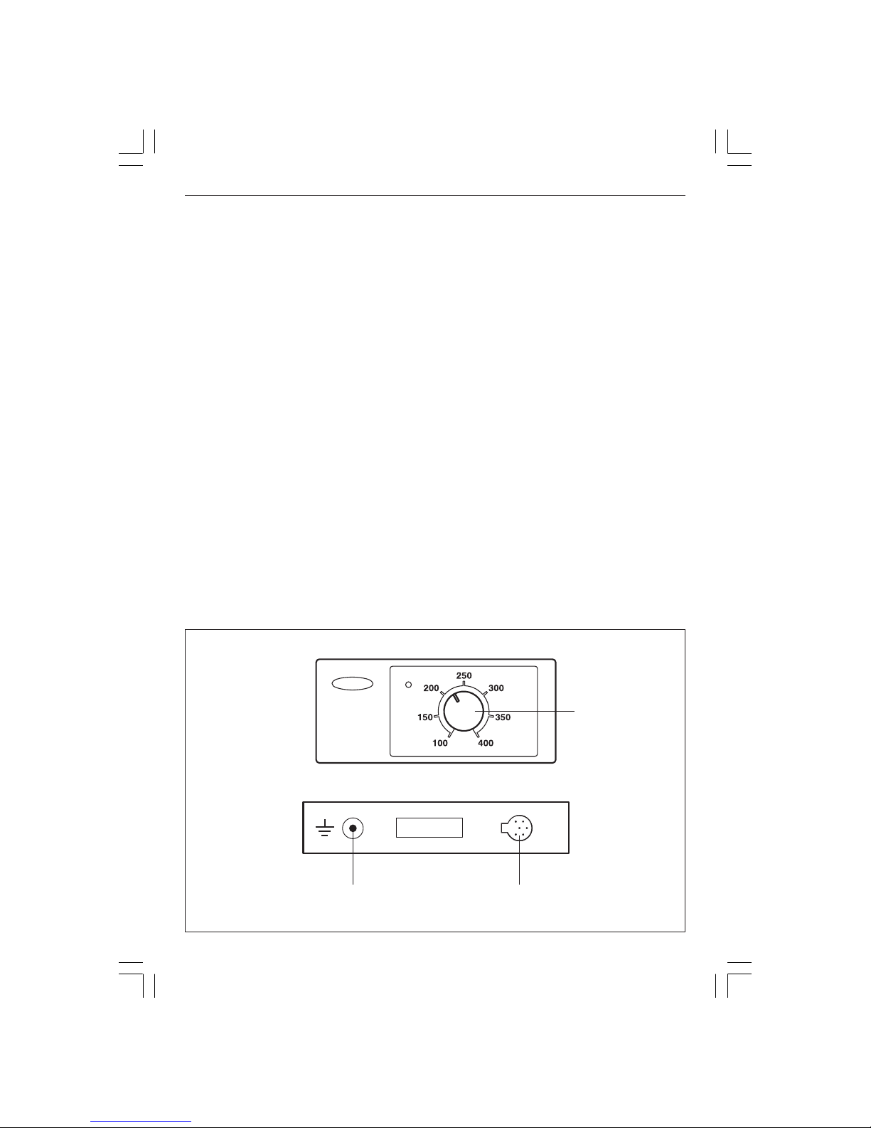
Temperature
selector
Equipotential
terminal
Soldering
connector
1
0425450-mb3260-230v.pmd 13/05/2004, 9:093
Page 3
MAINTENANCE
Soldering iron tip replacement
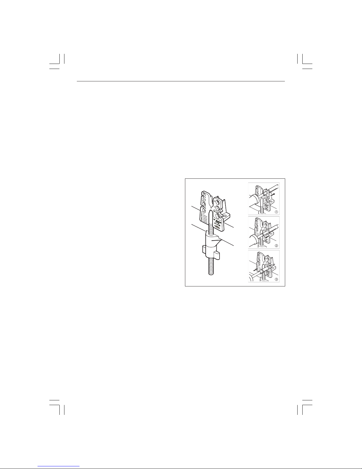
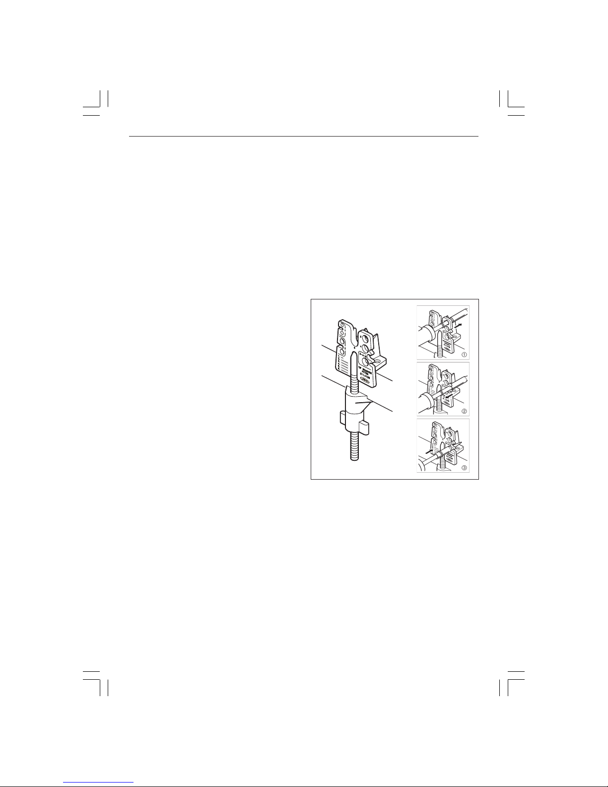
Use the tip removal device Ref. 0114108.
Remove the ring to release the tip.
Remove the tip by pulling the soldering
iron lengthwise without forcing the element.
Before fitting the new tip, clean the part of
the element which is covered by the tip, to
eliminate any contamination and facilitate the
insertion of the new tip.
Insert the new tip and make sure that it has
penetrated fully home, otherwise its thermic
performance would be altered and would
not correspond to the temperature reading.
Tip care
- To clean the tips, use the sponge included
with the stand and check it is slightly moisted.
Only deionised water (car battery water)Only deionised water (car battery water)
Only deionised water (car battery water)Only deionised water (car battery water)
Only deionised water (car battery water)
should be used in order to wet the spongeshould be used in order to wet the sponge
should be used in order to wet the spongeshould be used in order to wet the sponge
should be used in order to wet the sponge. If
normal water was to be used, it is very likely
that the tip will become dirty due to the salts
dissolved within the water.
- Do not file the tips or use abrasive tools which
may damage the tip’s protective surface
coating and avoid knocking them about.
- If the tip has been a long time without being
tinned, use the metal brush Ref. 0297705
adaptable to the support, to remove any dirt
and oxid.
ENGLISH
JBC reserves the right to after specifications without prior
notice.
Control Unit techical data
1. Safety transformer with mains separator:
LB-IB-TB-SB: 230V/24V 50Hz.
MB: 230V/12V 50Hz.
2. Analogue temperature range: from 100 to
400°C
3. Programmed temperature accurate to ±5%.
4. Green LED temperature adjustment optical
control.
5. Abides the CE standards for electrical
security, electromagnetical compatibility and
antistatic protection.
6. Equipotential connector is earth connected to
the plug feed of the station.
RECOMMENDATIONS FOR SOLDERING
- The components and the circuit should be
cleaned and degreased.
- Preferably select a temperature below 375°C.
Excess temperature may cause the printed
circuit tracks to break loose.
- The tip must be well tinned for good heat
conduction. If it has been inoperative for any
length of time, it should be retinned.
➀
➁
➂
2
0425450-mb3260-230v.pmd 13/05/2004, 9:094
Page 4
Agradecemos la confianza depositada en JBC al adquirir esta estación. Ha sido
fabricada con las más estrictas normas de calidad, para prestarle el mejor
servicio. Antes de poner en marcha el aparato, recomendamos leer con atención
las instrucciones que a continuación se detallan.
CARACTERISTICAS
Composición de las estaciones
MB 3260 230V Ref. 3260200
- Unidad de Control Ref. 3635200
- Soldador 5W
con punta R-0 D Ref. 3030000
- Soporte soldador MS 1300 Ref. 0290130
- Manual de instrucciones Ref. 0425450
LB 3200 230V Ref. 3200200
- Unidad de Control Ref. 3230200
- Soldador 20W
con punta B-05 D Ref. 3000000
- Soporte soldador LS 1100 Ref. 0290110
- Manual de instrucciones Ref. 0425450
IB 3210 230V Ref. 3210200
- Unidad de Control Ref. 3230200
- Soldador 50W
con punta R-10 D Ref. 3010000
- Soporte soldador US 1000 Ref. 0290100
- Manual de instrucciones Ref. 0425450
ESPAÑOL
TB 3220 230V Ref. 3220200
- Unidad de Control Ref. 3230200
- Soldador con aportación de
estaño 60W y punta C-20 D Ref. 3020000
- Soporte soldador TS 1200 Ref. 0290120
- Manual de instrucciones Ref. 0425450
SB 3240 230V Ref. 3240200
- Unidad de Control Ref. 3830200
- Soldador 70W
con punta T-55 D Ref. 3070000
- Soporte soldador US 1000 Ref. 0290100
- Manual de instrucciones Ref. 0425450
A la Unidad de Control Ref. 3230200, se pueden
conectar los soldadores de 20, 50, 60 y 70W,
aunque este último se recomienda utilizarlo con la
Unidad de Control Ref. 3830200, adaptada
especialmente a las necesidades de potencia de
este soldador. A esta unidad tambien se le pueden
conectar todos los soldadores exceptuando el
de 5W que requiere su propia unidad de control
Ref. 3635200.
Selector de
temperatura
Conector
equipotencial
Conector
soldador
3
0425450-mb3260-230v.pmd 13/05/2004, 9:095
Page 5
MANTENIMIENTO
Cambio de punta del soldador
Utilice el extractor de puntas Ref. 0114108.
Retire la anilla para liberar la punta.
Extraiga la punta tirando del soldador en
sentido longitudinal y sin forzar la resistencia.
Antes de colocar la nueva punta, limpie la parte
de la resistencia que queda cubierta por la
punta, para eliminar la contaminación que pudiera
tener y facilitar así la introducción del recambio.
Introduzca la nueva punta y asegúrese de
que ha penetrado a fondo, de lo contrario
alteraría su rendimiento térmico y no
correspondería la lectura de temperaturas.
Conservación de las puntas
- Para la limpieza de las puntas utilice la esponja
del soporte, que debe estar húmeda pero no
empapada de agua.
Es necesario utilizar sólo agua desionizadaEs necesario utilizar sólo agua desionizada
Es necesario utilizar sólo agua desionizadaEs necesario utilizar sólo agua desionizada
Es necesario utilizar sólo agua desionizada
para humedecer la esponja.para humedecer la esponja.
para humedecer la esponja.para humedecer la esponja.
para humedecer la esponja. Si utiliza agua
normal es muy probable que la punta se
ensucie con las sales disueltas que hay en
el agua.
- No lime ni utilice herramientas abrasivas que
puedan destruir la capa de protección
superficial de la punta y evite los golpes.
- Si la punta ha estado mucho tiempo sin ser
estañada, utilice el cepillo metálico Ref.
0297705 adaptable al soporte, para eliminar
el óxido y la suciedad.
Datos técnicos de la Unidad de Control
1. Transformador de seguridad separador de red:
LB-IB-TB-SB: 230V/24V 50Hz.
MB: 230V/12V 50Hz.
2. Selección analogica de la temperatura:
de 100 a 400°C
3. Precisión de la temperatura programada: ±5%.
4. Indicador de la regulación de la temperatura
por led verde.
5. Cumple la normativa CE sobre seguridad
electrica, compatibilidad electromagnética y
protección antiestatica.
6. El conector equipotencial está conectado a la
toma de tierra de la clavija de la estación.
RECOMENDACIONES PARA SOLDAR
- Los componentes y el circuito deben estar
límpios y desengrasados.
- Con preferencia seleccione una temperatura
inferior a 375°C. El exceso de temperatura
puede provocar el desprendimiento de las
pistas del circuito impreso.
- La punta debe estar bien estañada para
conducir bien el calor. Si permanece mucho
tiempo en reposo, estáñela de nuevo.
ESPAÑOL
JBC se reserva el derecho de introducir variaciones técnicas
sin previo aviso.
➀
➁
➂
4
0425450-mb3260-230v.pmd 13/05/2004, 9:096
Page 6

Nous vous remercions de la confiance que vous avez déposé en JBC en acquèrant cette
Station. Elle a été fabriquée dans les plus strictes normes de qualité pour vous rendre le
meilleur service. Avant de mettre en route l'apparéil, nous vous recommandons de lire
attentivement les instructions détaillées ci-après.
FRANÇAIS
CARACTERISTIQUES
Composition des stations
MB 3260 230V Réf. 3260200
- Unité de Contrôle Réf. 3635200
- Fer à souder 5W
avec panne R-0 D Réf. 3030000
- Support fer à souder MS 1300 Réf. 0290130
- Manuel d’instructions Réf. 0425450
LB 3200 230V Réf. 3200200
- Unité de Contrôle Réf. 3230200
- Fer à souder 20W
avec panne B-05 D Réf. 3000000
- Support fer à souder LS 1100 Réf. 0290110
- Manuel d’instructions Réf. 0425450
IB 3210 230V Réf. 3210200
- Unité de Contrôle Réf. 3230200
- Fer à souder 50W
avec panne R-10 D Réf. 3010000
- Support fer à souder US 1000 Réf. 0290100
- Manuel d’instructions Réf. 0425450
TB 3220 230V Réf. 3220200
- Unité de Contrôle Réf. 3230200
- Fer à souder avec apport
d’étain 60W et panne C-20 D Réf. 3020000
- Support fer à souder TS 1200 Réf. 0290120
- Manuel d’instructions Réf. 0425450
SB 3240 230V Réf. 3240200
- Unité de Contrôle Réf. 3830200
- Fer à souder 70W
avec panne T-55 D Réf. 3070000
- Support fer à souder US 1000 Réf. 0290100
- Manuel d’instructions Réf. 0425450
Sur l'unité de contrôle Réf. 3230200 il est possible
de connecter les fers à souder 20, 50, 60 et 70W,
bien qu'il soit conseillé d'utiliser ce dernier avec
l'Unité de Contrôle Réf. 3830200, spécialement
adaptée aux besoins en puissance de ce fer.
Sur cette derniere unité de contrôle on peut
également connecter tous les fers à souder à
l'exception du 5W qui recquière sa propre unité
de contrôle Réf. 3635200.
Sélecteur de
température
Connecteur
équipotentiel
Connecteur
fer à souder
5
0425450-mb3260-230v.pmd 13/05/2004, 9:097
Page 7

FRANÇAIS
Données techniques de l'Unité de Contrôle
1. Transformateur de sécurité séparateur du
réseau: LB-IB-TB-SB: 230V/24V 50Hz.
MB: 230V/12V 50Hz.
2. Sélection analogique de la température:
de 100 à 400°C
3. Précision de la température programmée: ±5%
4. Contrôle optique de régulation par led vert.
5. Elle est conforme aux normes CE pour la sécurité
électrique, la compatibilité électro-magnétique et
la protection antistatique.
6. La prise équipotentielle est connecté à la prise de
terre de la fiche d'alimentation de la station.
RECOMMANDATIONS POUR SOUDER
- Les composants et le circuit doivent être
propres et dégraissés.
- De préférence choisir une température
inférieure à 375°C. L’excès de température
peut provoquer le décollement des pistes du
circuit imprimé.
- La panne doit être bien étamée pour bien
conduire la chaleur. Lorsqu’elle est restée
longtemps au repos, l’étamer à nouveau.
ENTRETIEN
Remplacement de la panne du fer à souder
Utiliser l'extracteur de pannes Réf. 0114108.
Retirer l’anneau pour libérer la panne.
Extraire la panne en tirant sur le fer à souder
dans le sens de la longueur et sans forcer la
résistance.
Avant de placer la nouvelle panne, nettoyez
la partie de la résistance qui reste couverte
par la panne, afin d'éliminer les déchets qu'elle
pourrait avoir et faciliter ainsi l'introduction de
la pièce de rechange.
Introduire la nouvelle panne et assurez-vous
qu’elle soit enfoncée jusqu'au bout, sinon son
rendement thermique serait altéré et la lecture
des températures ne correspondrait pas.
Conservation des pannes
- Pour le nettoyage des buses veuillez utiliser l’éponge
du support, qui doit être légèrement humide.
Il est nécessaire d’utiliser de l’eau deioniséeIl est nécessaire d’utiliser de l’eau deionisée
Il est nécessaire d’utiliser de l’eau deioniséeIl est nécessaire d’utiliser de l’eau deionisée
Il est nécessaire d’utiliser de l’eau deionisée
pour humidifier l’épongepour humidifier l’éponge
pour humidifier l’épongepour humidifier l’éponge
pour humidifier l’éponge
..
..
. Si vous utilisez de
l’eau courante, il est très probable que la
panne soit contaminée par les sels dissous
contenus dans l’eau.
- Ne limez pas ni n’utilisez aucun outil abrasif
qui pourrait détruire la couche de protection
superficielle de la panne et évitez les coups.
- Si la panne n’a pas été étamée depuis longtemps,
utiliser la brosse métallique Réf. 0297705
(adaptable à tous les supports) pour la
débarrasser de toute trace de rouille et de saleté.
JBC se réserve le droit d'introduire des variations techniques
ou de conception sans préavis.
➀
➁
➂
6
0425450-mb3260-230v.pmd 13/05/2004, 9:098
Page 8

Wir danken Ihnen für das JBC mit dem Kauf dieser Station erwiesene Vertrauen.
Er ist mit den strengsten Qualitätsmaßstäben hergestellt, so dass Sie optimale
Lötergebnisse erwarten dürfen. Vor Inbetriebnahme des Geräts lesen Sie bitte die
vorliegende Betriebsanleitung aufmerksam durch.
DEUTSCH
TECHNISCHE MERKMALE
Aufbau
MB 3260 230V Ident-Nr. 3260200
- Steuereinheit Ident-Nr. 3635200
- Lötkolben
5W
mit Spitze R-0 D Ident-Nr. 3030000
- Lötkolbenständer MS 1300 Ident-Nr. 0290130
- Betriebsanleitungen Ident-Nr. 0425450
LB 3200 230V Ident-Nr. 3200200
- Steuereinheit Ident-Nr. 3230200
- Lötkolben 20W
mit Spitze B-05 D Ident-Nr. 3000000
- Lötkolbenständer LS 1100 Ident-Nr. 0290110
- Betriebsanleitungen Ident-Nr. 0425450
IB 3210 230V Ident-Nr. 3210200
- Steuereinheit Ident-Nr. 3230200
- Lötkolben 50W
mit Spitze R-10 D Ident-Nr. 3010000
- Lötkolbenständer US 1000 Ident-Nr. 0290100
- Betriebsanleitungen Ident-Nr. 0425450
TB 3220 230V Ident-Nr. 3220200
- Steuereinheit Ident-Nr. 3230200
- Lötkolben 60W mit Zinnzufuhr
und Spitze C-20 D Ident-Nr. 3020000
- Lötkolbenständer TS 1200 Ident-Nr. 0290120
- Betriebsanleitungen Ident-Nr. 0425450
SB 3240 230V Ref. 3240200
- Steuereinheit Ident-Nr. 3830200
- Lötkolben 70W
mit Spitze T-55 D Ident-Nr. 3070000
- Lötkolbenständer US 1000 Ident-Nr. 0290100
- Betriebsanleitungen Ident-Nr. 0425450
An die Steuereinheit Art.-.Nr. 3230200 können die
Lötkolben der Leistungen 20 W, 50 W, 60 W und
70 W angeschlossen werden; wir empfehlen jedoch,
letzteren nur mit der Steuereinheit
Art.-Nr. 3830200 einzusetzen, die speziell für die
Leistungsaufnahme dieses Kolbens ausgelegt ist.
An diese Steuereinheit können auch alle anderen
Lötkolben angeschlossen werden, mit Ausnahme
des 5-W-Kolbens, der seine eigene Steuereinheit
Art.-Nr. 3635200 benötigt.
Temperatur
Regler
Potentialausgleichsbuchse Buchse
Lötgerät
7
0425450-mb3260-230v.pmd 13/05/2004, 9:099
Page 9

DEUTSCH
Technische Angaben von der Steuereinheit
1. Sicherheitstransformator mit Netztrennung:
LB-IB-TB-SB: 230V/24V 50Hz.
MB: 230V/12V 50Hz.
2. Temperaturwahl: von 100 bis 400°C.
3. Genauigkeit der eingestellten Temp.: ±5%
4. Optische Temperaturkontrolle durch grüne
LED-Anzeige.
5. Erfüllt die Sicherheitsvorschriften der CE über
elektrische Sicherheit, elektromagnetische
Kompatibilität und antistatischer Schutz.
6. Die Equipotentialausgleichsbuchse is mit der
Erdung des Netzsteckers verbunden.
EMPFEHLUNGEN ZUM LÖTEN
- Komponenten und Leiterplatte müssen
sauber und entfettet sein.
- Möglichst immer mit Temperaturen unter 375°C
arbeiten. Höhere Temperaturen können ein
Ablösen der Leitungsbahnen zur Folge haben.
- Die Spitze sollte immer gut verzinnt sein
damit die Wärme besser fliest. Wurde der
Entlötkolben während einer längeren Zeit
nicht gebraucht, ist er erneut zu verzinnen.
Technische und konstruktive Änderungen vorbehalten.
WARTUNG
Wechsel der Lötspitze
Hierzu Spitzenabzieher Ident-Nr 0114108 verwenden.
Ring zur Freigabe der Spitze abziehen.
Die Spitze durch vorsichtiges Ziehen in
Längsrichtung lösen.
Vor Einsatz einer neuen Lötspitze, den
freigewordenen Teil des Heizkörpers reinigen,
um evtl. anhaftenden Schmutz zu entfernen
und das Einführen der neuen Spitze zu
erleichtern.
Neue Spitze vollständig aufschieben, da
sonst die Temperatuverhältnisse beeinflußt
werden und die ablesbaren Werte nicht dem
tatsächlichen Zustand entsprechen.
Behandlung der Spitzen
- Zur Reinigung der Spitzen ist der im
Kolbenständer vorgesehenen Schwamm zu
benutzen, der leicht mit Wasser angefeuchtet
sein sollte.
Es ist erforderlich zum Befeuchten desEs ist erforderlich zum Befeuchten des
Es ist erforderlich zum Befeuchten desEs ist erforderlich zum Befeuchten des
Es ist erforderlich zum Befeuchten des
Schwamms nur entionisiertes Wasser zuSchwamms nur entionisiertes Wasser zu
Schwamms nur entionisiertes Wasser zuSchwamms nur entionisiertes Wasser zu
Schwamms nur entionisiertes Wasser zu
verwendenverwenden
verwendenverwenden
verwenden. Wenn normales Wasser benutzt wird,
ist es sehr wahrscheinlich, dass die Spitze durch
die im Wasser gelösten Salze verschmutzt wird.
- Keine Feilen oder sonstige die Schutzschicht
der Spitze beeinträchtigende Werkzeuge
verwenden und vor Schlägen schützen.
- Wenn die Spitze lange Zeit nicht verzinnt
wurde, benutzen Sie bitte die an den Ständer
anpaßbare Metallbürste 0297705, um Rostund sonstige Schmutzreste zu entfernen.
➀
➁
➂
8
0425450-mb3260-230v.pmd 13/05/2004, 9:0910
Page 10

La ringraziamo per la fiducia riposta nella JBC con l’acquisto di questa stazione,
prodotta secondo le più rigide norme di qualità, per offrirle il servizio migliore.
Prima di accendere l’apparecchio, Le consigliamo di leggere attentamente le
istruzioni riportate qui di seguito.
ITALIANO
CARATTERISTICHE
Composizione della stazione
MB 3260 230V Rif. 3260200
- Unità di Controllo Rif. 3635200
- Saldatore 5W
con punta R-0 D Rif. 3030000
- Supporto saldatore MS 1300 Rif. 0290130
- Manuale d’istruzioni Rif. 0425450
LB 3200 230V Rif. 3200200
- Unità di Controllo Rif. 3230200
- Saldatore 20W
con punta B-05 D Rif. 3000000
- Supporto saldatore LS 1100 Rif. 0290110
- Manuale d’istruzioni Rif. 0425450
IB 3210 230V Rif. 3210200
- Unità di Controllo Rif. 3230200
- Saldatore 50W
con punta R-10 D Rif. 3010000
- Supporto saldatore US 1000 Rif. 0290100
- Manuale d’istruzioni Rif. 0425450
TB 3220 230V Rif. 3220200
- Unità di Controllo Rif. 3230200
- Saldatore con apporto
di stagno 60W e punta C-20 D Rif. 3020000
- Supporto saldatore TS 1200 Rif. 0290120
- Manuale d’istruzioni Rif. 0425450
SB 3240 230V Ref. 3240200
- Unità di Controllo Rif. 3830200
- Saldatore 70W
con punta T-55 D Rif. 3070000
- Supporto saldatore US 1000 Rif. 0290100
- Manuale d’istruzioni Rif. 0425450
A l'Unità di Controllo Rif. 3230200, si possono
collegare i saldatori da 20, 50, 60, e 70W,
quest'ultimo però si raccomanda di utilizzarlo
con l'unità di controllo Rif. 3830200, adatta
espressamente alla necessità di potenza di questo
saldatore. A questa unità si possono anche
collegare tutti i saldatori con esclusione del 5W
che necessita della propria unità di controllo
Rif. 3635200.
Selettore di
temperatura
Connettore
equipotenziale
Connettore
saldatore
9
0425450-mb3260-230v.pmd 13/05/2004, 9:0911
Page 11

ITALIANO
Dati tecnici dell’Unità di Controllo
1. Trasformatore di sicurezza con isolamento
della rete: LB-IB-TB-SB: 230V/24V 50Hz.
MB: 230V/12V 50Hz.
2. Selezione di temperatura analogiche:
da 100 a 400°C.
3. Precisione della temp. programmata: ±5%
4. Controllo ottico della regolazione della
temperatura mediante led verde.
5. Assolve la normativa CE riguardante la
sicurezza elettrica, compatibilita' electtromagnetica e protezione antistatica.
6. Il connettore equipotenziale è collegato alla
presa di terra della spina.
CONSIGLI PER SALDARE
- I componenti ed il circuito devono essere
puliti e sgrassati.
- Selezionare preferibilmente una temperatura
inferiore a 375°C. Una temperatura eccessiva
può causare il distacco delle piste del circuito
stampato.
- La punta deve essere ben stagnata per
condurre bene il calore. Quando rimane per
molto tempo in riposo, stagnarla di nuovo.
MANUTENZIONE
Cambio della punta del saldatore
Utilizzare l'estrattore di punte Rif. 0114108.
Togliere l’anello per liberare la punta.
Estrarre la punta tirando il saldatore in senso
longitudinale e senza forzare la resistenza.
Prima di sistemare la nuova punta, si deve
pulire la parte della resistenza che viene
coperta dalla punta, per eliminare eventuali
scorie e facilitare l'inserimento del ricambio.
Collocare la nuova punta ed assicurarsi che
sia penetrata fino in fondo, altrimenti ne
verrebbe alterato il rendimento termico, e la
lettura delle temperature non sarebbe quella
giusta.
Conservazione delle punte
- Per la pulizia delle punte utilizzare la
spugnetta, umida non molto bagnata,
incorporata nel supporto.
Per inumidire la spugna è necessario usarePer inumidire la spugna è necessario usare
Per inumidire la spugna è necessario usarePer inumidire la spugna è necessario usare
Per inumidire la spugna è necessario usare
solo acqua distillatasolo acqua distillata
solo acqua distillatasolo acqua distillata
solo acqua distillata. Se si utilizza acqua
normale il calcare può danneggiare la punta.
- Non limare, né utilizzare utensili abrasivi che
possano distruggere lo strato di protezione
superficiale della punta e evitare i colpi.
- Se la punta non è stata stagnata da molto
tempo, utilizzare la spazzola metallica,
Rif. 0297705, adattabile al supporto, per
eliminare la sporcizia e l’ossidazione.
JBC si reserva il diritto d'introdurre variazioni tecniche o di
disegno senza preavviso.
➀
➁
➂
10
0425450-mb3260-230v.pmd 13/05/2004, 9:0912
Page 12

ELECTRIC WIRING DIAGRAM
MB 3260
11
0425450-mb3260-230v.pmd 13/05/2004, 9:0913
Page 13

ELECTRIC WIRING DIAGRAM
LB 3200 - IB 3210 - TB 3220
12
0425450-mb3260-230v.pmd 13/05/2004, 9:0914
Page 14

ELECTRIC WIRING DIAGRAM
SB 3240
13
0425450-mb3260-230v.pmd 13/05/2004, 9:0915
Page 15

14
0425450-mb3260-230v.pmd 13/05/2004, 9:0916
Page 16

15
0425450-mb3260-230v.pmd 13/05/2004, 9:0917
Page 17

16
0425450-mb3260-230v.pmd 13/05/2004, 9:0918
Page 18

WARRANTY ENGLISH
The JBC 2 years warranty, guarantees
this equipment against all manufacturing
defects, covering the replacement of
defective parts and all necessary labour.
Warranty does not cover product wear
due to use or mis-use.
In order for the warranty to be valid,
equipment must be returned, postage
paid, to the dealer where it was
purchased enclosing this, fully filled in,
sheet.
GARANTIA ESPAÑOL
JBC garantiza este aparato durante 2
años, contra todo defecto de fabricación,
cubriendo la reparación con sustitución
de las piezas defectuosas e incluyendo
la mano de obra necesaria.
Quedan excluidas de esta garantía las
averías provocadas por mal uso del
aparato y desgaste por uso.
Es indispensable para acogerse a esta
garantía el envio del aparato al
distribuidor donde se adquirió, a portes
pagados, adjuntando esta hoja
debidamente cumplimentada.
GARANTIE FRANÇAIS
JBC garantit cet appareil 2 ans contre
tout défaut de fabrication. Cela comprend
la réparation, le remplacement des
pièces défectueuses et la main d'oeuvre
nécessaire.
La garantie ne couvre pas l’usure liée à
l’utilisation et à la mauvaise utilisation du
matériel.
Pour bénéficier de cette garantie il est
indispensable d'envoyer l'appareil chez
le distributeur où il a été acquis, en ports
payés, en joignant cette fiche dûment
remplie.
✂
0425450-mb3260-230v.pmd 13/05/2004, 9:0919
Page 19

0425450-0504
GARANTIE DEUTSCH
Für das vorliegende Gerät übernimmt
JBC eine Garantie von 2 Jahren, für alle
Fabrikationsfehler. Diese Garantie
schliesst die Reparatur bzw. den Ersatz
der defekten Teile sowie die
entsprechenden Arbeitskosten ein.
Ausgeschlossen von dieser
Garantieleistung sind durch
unsachgemässen Gebrauch
hervorgerufene Betriebsstörungen und
normale Gebrauchsabnützungen.
Zur Inanspruchnahme dieser Garantie
muss das Gerät portofrei an den
Vertriebshändler geschickt werden, bei
dem es gekauft wurde. Fügen Sie dieses
vollständig ausgefüllte Blatt bei.
GARANZIA ITALIANO
La JBC garantisce quest'apparato 2
anni contro ogni difetto di fabbricazione,
e copre la riparazione e la sostituzione
dei pezzi difettosi, includendo la mano
d'opera necessaria.
Sono escluse da questa garanzia le
avarie provocate da cattivo uso
dell'apparato e logorio da utilizzo.
Per usufruire di questa garanzia, è
indispensabile inviare, in porto franco,
l'apparato al distributore presso il quale
è stato acquistato, unitamente a questo
foglio debitamente compilato.
DATE OF PURCHASE
FECHA DE COMPRA
DATE D'ACHAT
KAUFDATUM
DATA DI ACQUISTO
STAMP OF DEALER
SELLO DEL DISTRIBUIDOR
CACHET DU DISTRIBUTEUR
STEMPEL DES HÄNDLERS
TIMBRO DEL DISTRIBUTORE
SERIAL Nº
✂
MANUFACTURED BY
JBC Industrias, S.A.
Ramón y Cajal, 3 - 08750 MOLINS DE REI
BARCELONA - SPAIN
Tel.: +34 93 325 32 00 - Fax: +34 93 680 49 70
http://www.jbctools.com e-mail:info@jbctools.com
0425450-mb3260-230v.pmd 13/05/2004, 9:0920
 Loading...