

Page 1
www.jbctools.com
INSTRUCTION MANUAL
Hot Air Station
without Extractor desk
Ref. JTSE-QA
Page 2
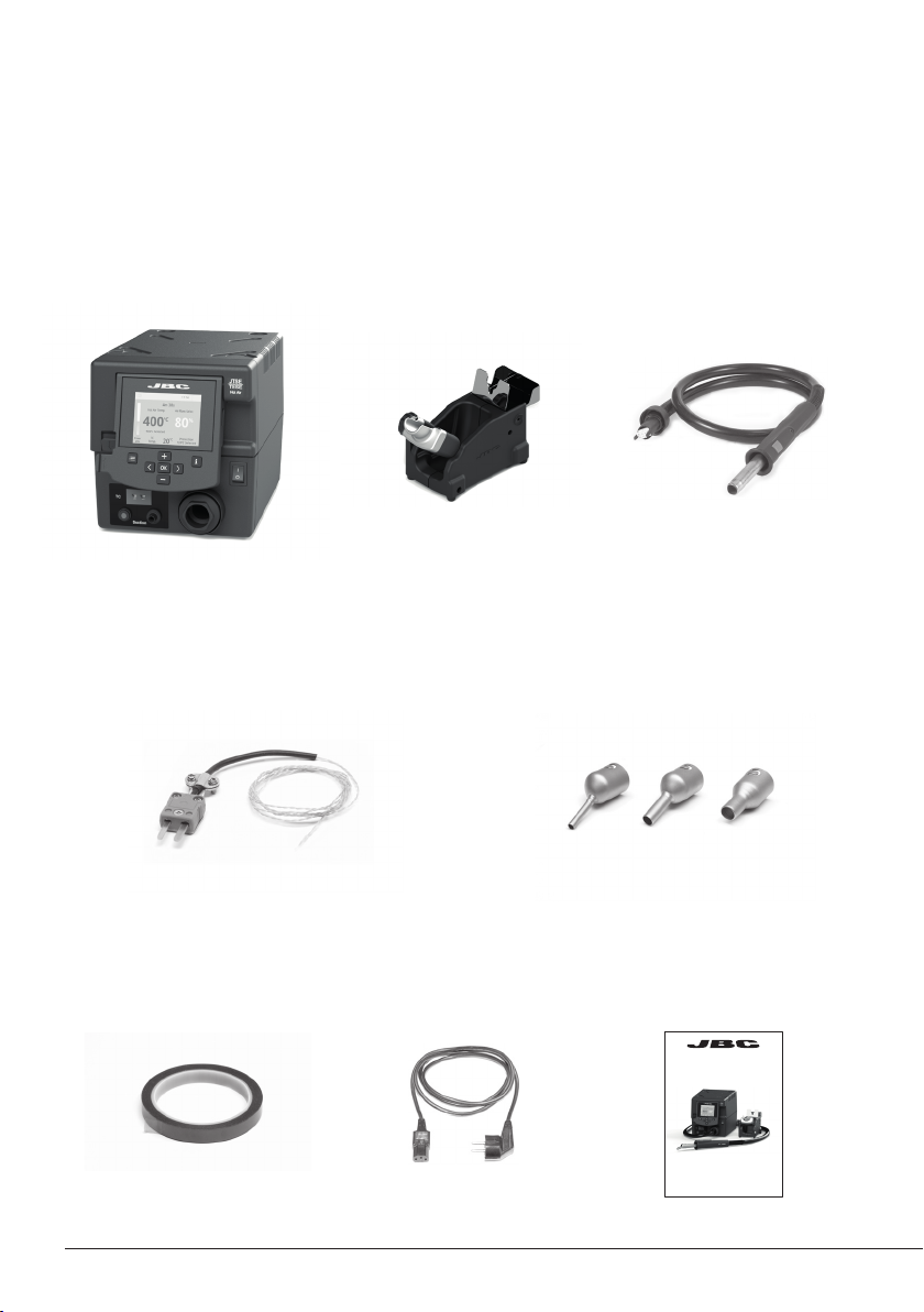
Packing List
The following items are included:
JTSE Control Unit .........1 unit
Ref. JTSE-1A (100V / 120V)
Stand ................................1 un it
Re f. J T- SE
JTSE-2A (230V )
Thermocouple type K ..................................1 unit
Ref. PH218
Heater hose set .............1 uni t
Ref. JT-T1A (100V / 120V)
JT-T2A (230V)
Nozzles ............................................................. 1 unit
Ref. JN2015
JN 2012
JN2020
Kapton Tape ................. 1 unit
Ref. PH217
2
2
Power cable ....................1 unit
Ref. 0009417 (100V / 120V)
0009401 (230V)
Manual ...............................1 un it
Re f. 0 018814
www.jbctools.com
INSTRUCTION MANUAL
Hot Air Station
without Extractor desk
Ref. JTSE-QA
Page 3
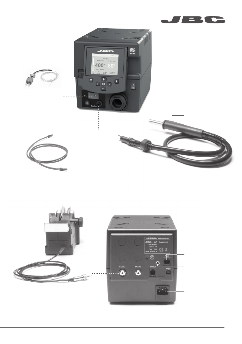
Features
Thermocouple type K
Activates the suction pump
Suction Tube
For tripods and extractors
Re f. J T- SE
www.jbctools.com
USB-A connector
Heating element
Hot Air button
(On / Off )
Heater Hose set
Re f. J T-T1A (10 0V/12 0V)
JT-T2A (230V)
Stand
P-005 Pedal connector
Auxiliar connector
Equipotential connector
USB connector
Robot RS232 connector
Power Socket
Fuse
3
3
Page 4

JTSE / TESE Work Screen
The JTSE /TESE offers an intuitive user interface which provides quick access to station pa rameters.
Default PIN: 0105
Status bar
Instant power
supplied to
heater
Current
air
temp.
Air
temp.
selected
Current
Externa l
TC temp.
Menu Options
Set the station
parameters
4m 38s
Hot Air Temp. Air Flow Selec.
ºC
400
400ºC Selected
Power
45%
TC
Temp.
20
Set the tool
parameters
80
ºC
120ºC Selected
17:14
%
Protection
Status
indicator
Selected
Air flow
Selected
External Tc
temp.
Station
Information
Display the hours
worked in each cycle
Station Tools Counters
It is possible to
choose the language
from a list.
ResetLanguage
4
4
Allows you to carry
out an overall station
reset restoring all the
parameters to their
default values.
Page 5
Point
2/5
Temp
250
ºC
Flow
60
%
Time
2m 30s
3m 18s
Hot Air Temp
240
ºC ºC %
Ext. TC Temp
20
Air Flow
80
3m 18s
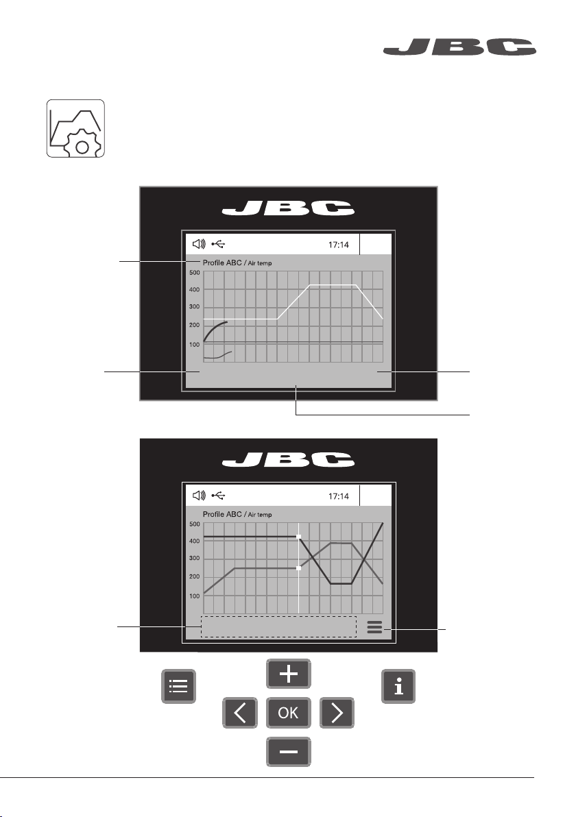
Advanced functionalities
To work with profiles it is essential to use the RWB / RWS / RWT rework arms. The
Rework Arms supports the Hot Air Heater maintaining the distance and position to
the component.
www.jbctools.com
Profiles
Profile name
Current
air temp.
Edit Mode
In this mode you can set up or edit as many as 25 profiles of temperature and air flow.
Current
air flow
Current
Externa l
TC temp.
Data for
these points
Menu
Options
· Add point
· Delete point
· Load profile
· Save profile
· Exit
5
5
Page 6

450
400
350
300
250
150
100
50
200
Power Temp
Graphics
Power (%)
Temperature
JBC Net
Files
Update
By pressing Graphics in the main MENU, temperature and power fi gures in real time
are displayed. This helps you decide which tip to use to obtain the best quality solder
joints.
17:14
Ext. te mp
Externa l
temp.
The fi rst system to optimize traceability in soldering
- Get greater quality and control in your production
- Manage your whole soldering process remotely in real time
Export graphics
Insert a USB flash drive into the USB-A
connector to save your soldering process
in csv format.
Station update
Download the JBC Update File from
www.jbctools.com/software.html
Insert the USB flash drive with the file downloadedto the station.
System notifications
The following icons will be displayed on the screen’s status bar.
USB fl ash drive is connected.
Station is controlled by a PC.
Station is controlled by a robot.
66
Station sof tware update.
Press INFO to start the process.
Warning.
Press INFO for failure description.
Er r or.
Press INFO for failure description,
the type of error and how to proceed.
Page 7

www.jbctools.com
Adjustable Stand
Adjust the tool holder angle to suit your work position.
Operation Modes
1. From the Tool Settings Menu, select the mode to activate the tool depending on the task.
Tool button
Press
Press the start/stop button to blow hot air. Press the Pedal to blow hot air and release to
2. The tool stops blowing when pressing the start/stop button.
If the stand is connected to the station and for safety it will also stop when returned to the stand.
Pedal*
Press
stop.
*The P-005 Pedal is not supplied with this
station. See our website.
7
7
Page 8

Operation
Position the extractor with the
appropriate suction cup and
press the suction button.
2. Heating
Heat the component.
3. Extracting1. Placing
The component lifts off
automatically when the
solder melts.
Protectors & Extractors
For small components (fig. 1 and 2). For large components (fig. 3 and 4).
We recommend using the protector + tripod We recommend using the manual extractors
1 2 3 4
8
8
Page 9

www.jbctools.com
Using the Thermocouple type K
Connect a TC type K (PH218) to the station and use it as a protection or regulation sensor.
You can define its use mode by means of the “Ext TC mode” option in the “Tool” menu.
You can choose from two work modes:
Regulation: the station regulates the air
temperature automatically to maintain the
External Thermocouple (TC) temperature.
Fix the TC with Kapton Tape (Ref. PH217) as near as possible to the component being worked on.
If Kapton tape is not ESD you must use an ionizer.
IPC* does not recommend exceeding ramp-up rates over 3-4ºC / sec. (5-7ºF / sec) so as to reduce
the risk of thermal stress on the PCB.
Protection: the station cuts the air supply off
when the External Thermocouple (TC)
temperature is reached.
* IPC was founded in the U.S. in 1957 as the Institute for Printed Circuits.
9
9
Page 10

Quick Nozzle Changer
Changing nozzles quickly and safely.
2
Turn the tool
off and handle with
care. The heating
element and the
nozzle are still hot.
Compatible Nozzles
The JT-TA works with JT nozzles. Find the model that best suits your soldering needs in www.jbctools.com
Straight Bent Flat
Ø Ø A x B
1
* Ref. Shape Ø Size
(mm)ØSize (in)
* JN2020 Straight Ø 8 Ø 0.31
* JN8417 Straight Ø 10 Ø 0.4
* JN2015 Bent Ø 4 Ø 0 .16
* JN2 012 Bent Ø 6 Ø 0.24
* JN6633 Bent Ø 8 Ø 0.31
* JN76 37 Flat 10 x 2 0.4 x 0.08
* JN7638 Flat 20 x 2 0.8 x 0.08
* JN7639 Flat 30 x 2 1.18 x 0.08
In case of a loosely fitting nozzle:
1. Push the nozzle tab inwards with a screwdriver or flat-nosed pliers.
10
10
* Not included
2. Insert the nozzle into the JT-TA again.
Page 11

www.jbctools.com
Replacing the Heating Element
Only perform this operation when the element is cold and the unit is disconnected from the mains.
1. Loosen the screw.
2. Pull the heating element out of the handle.
3. Connect the new heating element, ensuring it is pushed all the way in.
4. Tighten the screw.
Heating Element
Ref. 0014107 (230V)
0014105 (100V / 120V)
Handle
Ref. 0009829
Heating Hose Set
Ref. JT-T1A (100V / 120V)
JT-T2A (230V)
Changing the JT-TA Heater Hose Set
1. Unplug the power cable.
2. Use a spanner to unscrew the nut.
3. Make sure that the new heater tube fits into
the grooves in the socket.
4. Tighten the screw.
11
11
Page 12

Maintenance
Before carrying out maintenance, always allow the equipment to cool.
- Clean the station screen with a glass cleaner
or a damp cloth.
- Use a damp cloth to clean the casing and the
tool. Alcohol can only be used to clean the
metal parts.
- Periodically check that the metal parts of the
tool and stand are clean so that the station
can detect the tool status.
- Periodically check all cables and tubes.
- Replace a blown fuse as follows:
1. Pull of f the fuse holder and remove the
fuse. If necessar y use a tool to lever it off.
Fuse holder
- Replace any defective or damaged pieces. Use original JBC spare parts only.
- Repairs should only be performed by a JBC authorized technical service.
2. Insert the new fuse into the fuse holder
and return it to the station.
Fuse
Fuse holder
12
12
Page 13

www.jbctools.com
Safety
It is imperative to follow safety guidelines to prevent electric
shock, injury, fire or explosion.
- Do not use the units for any purpose other than soldering or rework. Incorrect use may cause fire.
- The power cord must be plugged into approved bases. Make sure that it is properly grounded
before use. When unplugging it, hold the plug, not the wire.
- Do not work on electrically live parts.
- The tool should be placed in the stand when not in use to turn off the hot air. The soldering tip, the
metal part of the tool and the stand may still be hot even when the station is turned of f. Handle with
care, including when adjusting the stand position.
- Do not leave the appliance unattended when it is on.
- Do not cover the ventilation grills. Heat can cause inflamable products to ignite.
- Avoid the contact of flux with skin or eyes to prevent irritation.
- Be careful with the fumes produced when soldering.
- Keep your workplace clean and tidy. Wear appropriate protection glasses and gloves when
working to avoid personal harm.
- Utmost care must be taken with liquid tin waste which can cause burns.
- This appliance can be used by children over the age of eight and also persons with reduced
physical, sensory or mental capabilities or lack of experience provided that they have been given
adequate supervision or instruction concerning use of the appliance and understand the hazards
involved. Children must not play with the appliance.
- Maintenance must not be carried out by children unless supervised.
13
13
Page 14

有害物质含量表
产品中有害物质的名称及含量
有害物质
部件名称
铅(Pb) 汞(Hg) 镉(Cd)
烙铁头 O O O O O O
手柄 O O O O O O
电源线 O O O O O O
主机 O O O O O O
电源插座 O O O O O O
保险丝 O O O O O O
主开关 O O O O O O
六价铬
(Cr(VI))
多溴联苯
(PBB)
多溴二苯醚
(PBDE)
电位连接 X O O O O O
变压器 O O O O O O
线路板 X O O O O O
O 表示该有害物质在该部件所有均质材料中的含量均在GB/T 26572 规定的限量要求以下。
X 表示该有害物质至少在该部件的某一均质材料中的含量超出GB/T 26572 规定的限量要求。
14
14
Page 15

Specifications
JTSE -1A 100V - 120V 50/60Hz. Input fuse: 8A. Rated current: 7A
JTSE-2A 230V 50/60Hz. Input fuse: 4A. Rated current: 3A
- Nominal power: 700W
- Temperature selection: Room temp. / 150 - 450 °C (300 - 840 °F)
Cool mode: T off. Used to blow air at room temperature
- Ambient operating temp.: 10 - 50 ºC (50 - 122 ºF)
- Air flow regulation: 5 - 50 SLPM
- Vacuum: 30% / 228 mmHg / 9 inHg
- Connectors: USB-A / USB-B
RJ12 for RS232
Pedal for P-005
- Control Unit Weight: 1,9 kg (10.86 lb)
- Control Unit Dimensions: 148 x 184 x 140 mm (5.83 x 7.24 x 5.51 in)
- Total Package: 474 x 368 x 195 mm / 4.62 kg
18.7 x 14.5 x 7.7 in / 10.2 lb
Complies with CE standards.
ESD protected.
www.jbctools.com
15
15
Page 16

Warranty
JBC’s 2 year warranty covers this equipment against
all manufacturing defects, including the replacement
of defective parts and labour.
Warrant y does not cover product wear or misuse.
In order for the warranty to be valid, equipment must
be returned, postage paid, to the dealer where it was
purchased.
Get 1 extra year JBC warranty by registering here:
https://www.jbctools.com/productregistration/
within 3 0 days of purchase.
This product should not be thrown in the garbage.
In accordance with the European directive 2012/19/EU, electronic equipment at the end of its life must
be collected and returned to an authorized recycling facility.
www.jbctools.com
00 188 14- 0819
 Loading...