

Page 1

Index Page
English 1
Español 7
Français 13
Deutsch 19
Italiano 25
HOT-AIR FLOW DESOLDERING STATION
JT 6040
Page 2

ENGLISH
We appreciate the confidence you have placed in JBC in purchasing this station.
It is manufactured to the most stringent quality standards in order to give you the
best possible service. Before turning on your station, we recommend you to read
these instructions carefully.
SPECIFICATIONS
The JT6040 is a hot air generating station intended
for repair work involving electronic circuits with
SMDs of any size.
- JT 6040 230V 50Hz: Ref. 6040200
- JT 6040 115V 60Hz: Ref. 6040100
The station’s components
- Control Unit with 700 W heater
- JT 1800 heater stand Ref. 0930180
- Extractor stand Ref. 0932845
- Set of 5 protectors (Fig. 1, page 34)
- Set of 5 extractors (Fig. 2, page 34)
- 2 tripods for the protectors (Fig. 1, page 34)
- Set of 4 suction cups Ref. 0930110
- 3 nozzles
In order to make the nozzles removal easier, the
stand has a special bushing.
(Fig. 3, page 34).
- Suction tube with connectors: Ref. 0932330
- Pedal with cable and connector Ref. 0964551
- Spare filters Ref. 0966689
- Instruction manual Ref. 0935400
Control Unit technical specifications
- Temperature selection from 150 to 450°C
- Accuracy of selected temperature: ± 5%
- Air flow regulation: 6-34 l/min
- Station's maximum power: 750W
- Abides the CE standards for electrical security,
electromagnetical compatibility and antistatic
protection.
- Weight of complete unit: 6.2 kg
1
Page 3
ENGLISH
OPERATION
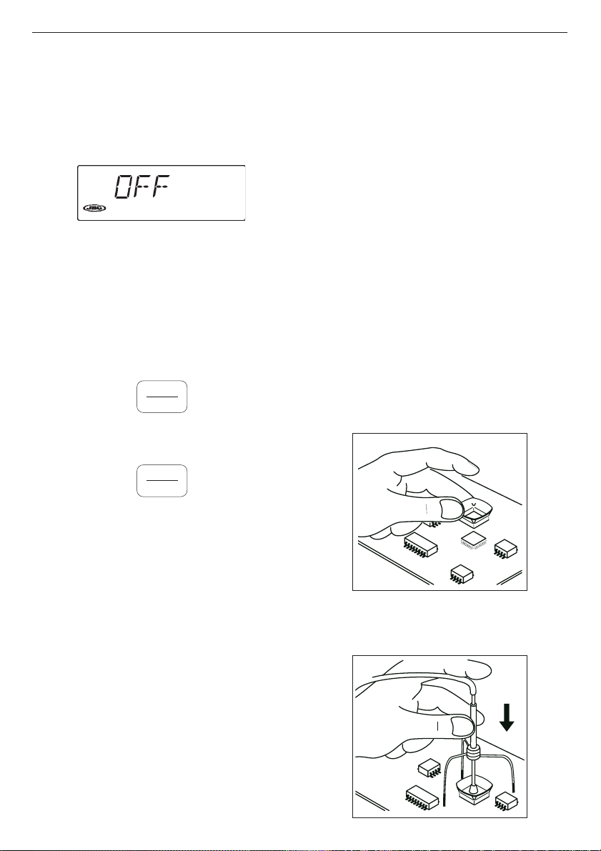
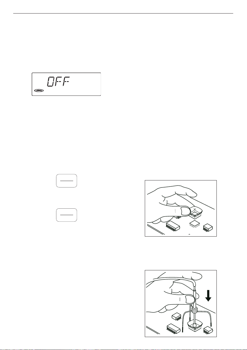
Turning on
Turn on using the switch on the rear of the
control unit. The version of the software will first
be displayed, and then the OFF screen will
appear.
Description of controls
- PEDAL:
Hot air is produced when it is held down.
Releasing it returns the system to OFF, though
the turbine continues to operate until the air
temperature falls below 100°C.
- KEYS:
HEAT
ON
OFF
Performs the same function as the pedal.
VACUUM
ON
OFF
On/off switch for the suction pump.
DESOLDERING PROCEDURE
Depending on their size, the protectors and
extractors are grouped on the console in three
colours - yellow, orange and red - like the
temperature and air-flow regulating scales on the
front panel of the station. This means that, according
to the extractor size, we would recommend air-flow
and temperature selection to match colour codes.
We would also recommend the use of the nozzles
of larger diameter, reserving the smallest one
(diam. 4 mm) for desoldering small components
such as resistors, condensers and the like, bearing
in mind that with this small nozzle the concentration
of heat is greater and care must be taken to avoid
burning the printed circuit; we recommend keeping
below a temperature of 350 °C and air flow of 6.
Depending on the size of the integrated circuit to
be desoldered, you will have to use:
A)Protector + trípod
B) Extractor
C)Tripod
A) Protector + tripod:
- Select protector and tripod size in function of
the IC to be desoldered and place it over the
component.
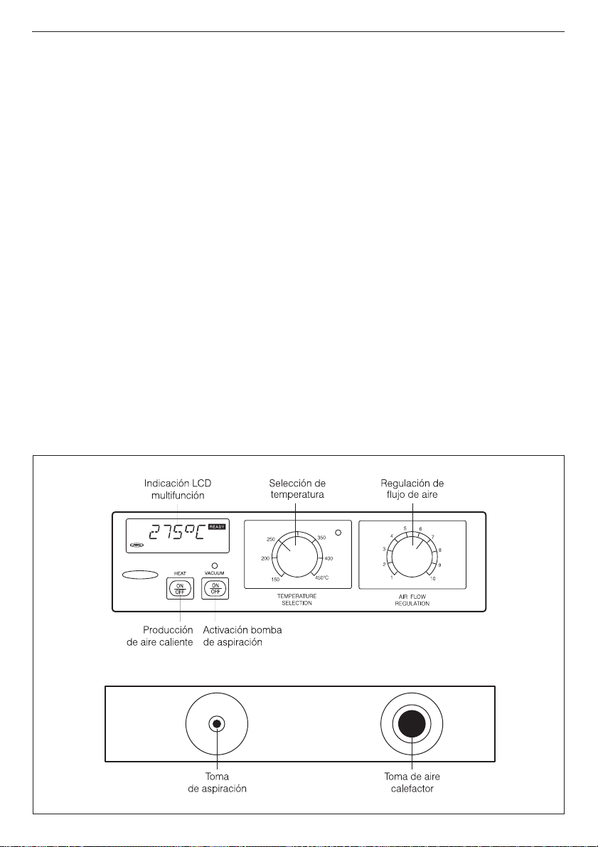
- CONTROLS:
TEMPERATURE
SELECTION
This enables temperatures from 150 to 450°C
to be selected.
The display shows the actual air temperature
when the unit is working.
AIR FLOW
REGULATION
This enables the air flow to be set on a scale
from 1 (corresponding to the lowest setting
of 6 l/min) to 10 (corresponding to the highest
of 34 l/min).
- Use the VACUUM button to start the suction
pump and then fit the tripod. Press the sucker
down until it sticks onto the component.
2
Page 4
ENGLISH
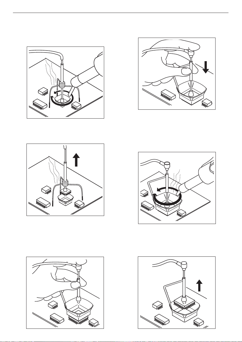
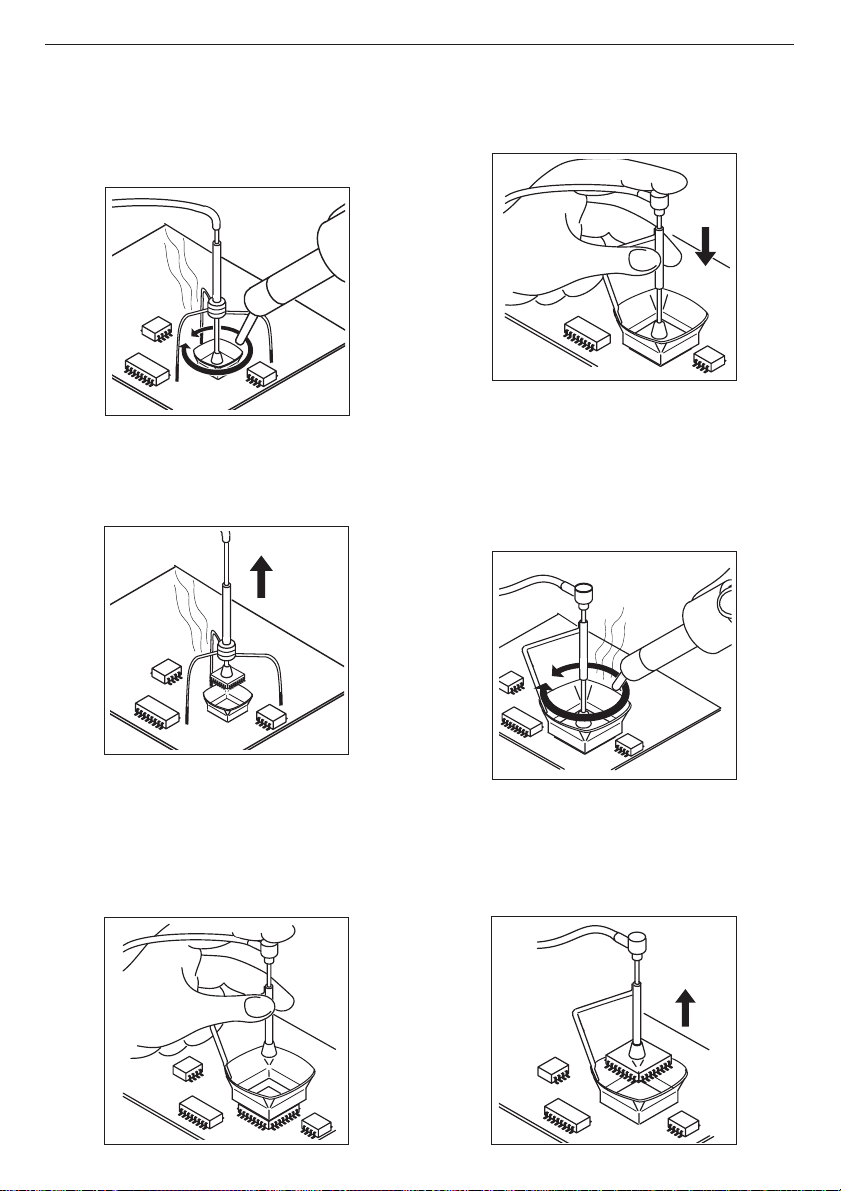
- Use the pedal to start the hot-air generator,
directing it with a circular movement at the
component terminals and taking care to
distribute the heat evenly.
- When the soldering flux turns liquid the extractor
will automatically lift the component.
- Fit the extractor and press the sucker down until
it sticks onto the component.
- Use the pedal to start the hot-air generator,
directing it with a circular movement at the
component terminals and taking care to distribute
the heat evenly.
B)Extractor:
- Select extractor size in function of the IC to be
desoldered. Use the
the suction pump.
VACUUMVACUUM
VACUUM button to start
VACUUMVACUUM
- When the soldering flux turns liquid the extractor
will automatically lift the component.
3
Page 5

ENGLISH
There are different models of protectors and
extractors as accessories.
The measurements of all the extractors and
protectors are given on page 34 of instructions
manual.
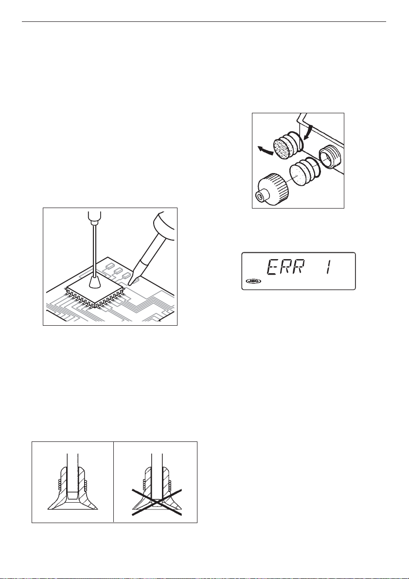
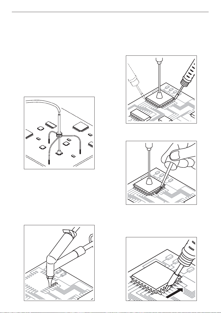
C)Tripod:
For small components for which an extractor
cannot be used, we recommend use of tripod 20
Ref. 0932050, as shown in the figure.
Use the tripod 40 Ref. 0932250 for larger integrated
circuits.
2 Place the component or printed circuit.
3 When the component is correctly placed,
solder its pins.In the case of integrated circuits
of the Flat Pack type, first solder one pin of
every IC angle to fix it in place in the circuits.
4 Apply Flux FL9582 in pads and leads.
SOLDERING PROCEDURE
1 After desoldering the component, any solder
left on the printed circuit should be removed
using a desoldering station. We recommend
one of our stations, the RP 5100, the RA 5150
or the TA 5120 station.
5 Solder the remaining pins. For that, we
recommend you use our soldering station,
the Advanced Series, which has 2 models
of irons.
4
Page 6
ENGLISH
Soldering Iron 2010 for great precision tasks,
like SMD solders, etc.
Soldering Iron 2045 for general soldering
tasks in professional electronics.
These soldering irons have a wide range of
cartridges with different models of tips. The
cartridge 2045-009 and 2045-010 are
specially designed for soldering SMD circuits
of the QFP and PLCC types.
Solder wire with a diameter of between 0.5 and
0.7 mm should be used.
6 Depending on the nature of the component to
be soldered, use soldering paste together
with our hot air station JE 6050, which gives
very accurate air-flow regulation, between
1 and 9 l/min.
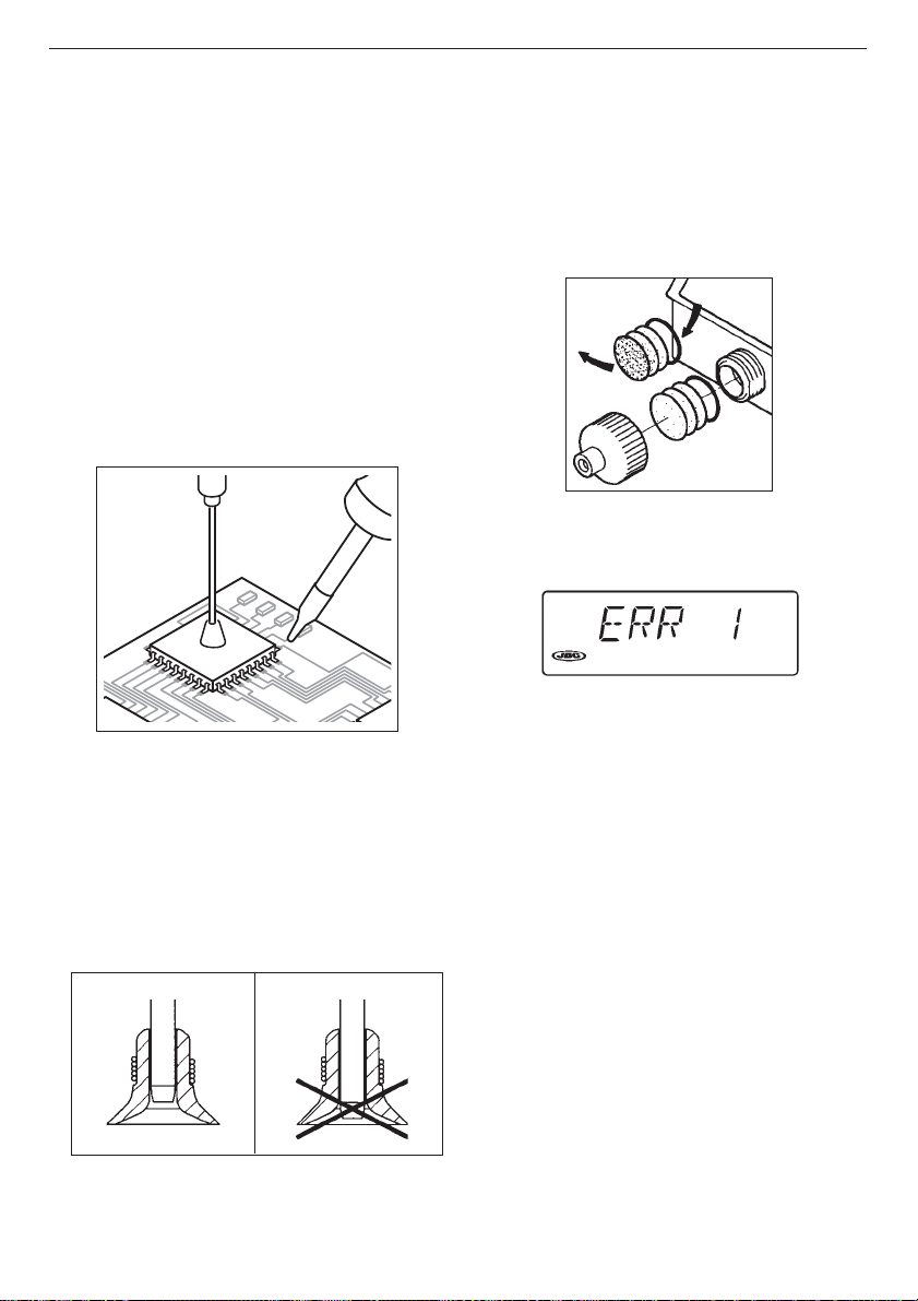
Disconnect the filter plug tube. Unscrew the
plug and remove the gasket.
Remove the three paper filters, throw away the
dirty ones and replace with new ones.
Insert the three filters and the gasket in this order;
screw-up the cover and connect the tube.
Check for air tightness.
Error messages
Whenever the ERR message appears, the
equipment turns itself off completely.
The following messages are displayed:
OPERATING INCIDENTS
The suction cup does not adhere to the
component.
Deficient aspiration, Vacuum.
1 Verify if the suction cup is well placed and in
perfect condition.
2 Verify the filters at the entrance of the pump,
and change them if dirty or obturated, therefor:
- BLANK SCREEN
Power failure.
Check for blown fuses.
- ERR 1
The temperature will not rise.
Possible causes: heating element open or blown
fuse.
- ERR 2
The temperature is rising out of control.
Possible causes: shorted triac or insufficient
airflow.
- ERR 3
No reading from the thermocouple.
Possible cause: open thermocouple.
- ERR 4
Erratic readings from the thermocouple.
Possible causes: the thermopar or its
connections are in poor condition.
5
Page 7

ENGLISH
- ERR 5
Inability to save information to, or retrieve
information from, the permanent E2ROM
memory.
- ERR 6
Insufficient air flow which causes an excesive
rise of the heating temperature.
Before recuperating this type of error you must
wait until the temperature goes down.
Possible causes: leaking or blocked air conducts
or faulty air pump.
To recuperate any of these errors actuate the
general switch at the back of the station, the
pedal should not be pushed at this moment.
JBC reserves the right to make technical changes without
prior notification.
6
Page 8
ESPAÑOL
Agradecemos la confianza depositada en JBC al adquirir esta estación. Ha sido
fabricada con las más estrictas normas de calidad para prestarle el mejor servicio.
Antes de poner en marcha el aparato, recomendamos leer con atención las
instrucciones que a continuación se detallan.
CARACTERISTICAS
La JT 6040 es una estación generadora de aire
caliente, destinada a trabajos de reparación de
circuitos electrónicos, con componentes de
tecnología SMD de cualquier tamaño.
- JT 6040 230V 50Hz: Ref. 6040200
- JT 6040 115V 60Hz: Ref. 6040100
Composición de la estación
- Unidad de Control con calefactor 700 W
- Soporte calefactor JT 1800 Ref. 0930180
- Soporte para extractores Ref. 0932845
- Conjunto de 5 protectores (Fig. 1, pág. 34)
- Conjunto de 5 extractores (Fig. 2, pág. 34)
- 2 trípodes para los protectores (Fig. 1, pág. 34)
- Conjunto de 4 ventosas Ref. 0930110
- 3 Boquillas
Para facilitar la extracción de las boquillas el
soporte del calefactor dispone de un útil
especial (Fig 3, pág. 34).
- Tubo aspiración con conectores Ref. 0932330
- Pedal con cable y conector Ref. 0964551
- Filtros de recambio Ref. 0966689
- Manual de instrucciones Ref. 0935400
Datos técnicos de la Unidad de Control
- Selección temperatura entre 150 y 450°C.
- Precisión de la temperatura seleccionada ±5%.
- Regulación del caudal de aire de 6 a 34 l/min.
- Potencia máxima de la estación 750W.
- Cumple la normativa CE sobre seguridad
eléctrica, compatibilidad electromagnética y
protección antiestática.
- Peso del equipo completo 6,2 kg.
7
Page 9
ESPAÑOL
FUNCIONAMIENTO
Puesta en marcha
Accione el interruptor situado en la parte
posterior de la unidad de control.
Seguidamente se visualizará la versión del
software e inmediatamente aparecerá la
pantalla OFF.
Descripción de los mandos
- PEDAL:
Activa la producción de aire caliente mientras
se mantiene accionado.
Cuando se deja de presionar, el sistema
retorna a OFF, pero la turbina continua
funcionando hasta que la temperatura del
aire es inferior a 100 °C.
- TECLAS:
HEAT
ON
OFF
Tiene la misma función que el pedal.
PROCESO PARA DESOLDAR
Los protectores y extractores, dependiendo de
su tamaño, están agrupados en el pupitre en
tres colores, amarillo, naranja y rojo al igual que
las escalas de regulación de temperatura y
caudal de aire. Aconsejamos hacer coincidir los
colores de los protectores y extractores con los
de las escalas de regulación.
Recomendamos utilizar las boquillas de mayor
diámetro y reservar la mas pequeña (ø4mm) para
la desoldadura de pequeños componentes como
resistencias, condensadores, etc, téngase en
cuenta que con esta boquilla la concentración de
calor es mayor, por lo que para evitar quemar el
circuito impreso, aconsejamos no sobrepasar la
temperatura de 350 °C y el caudal de aire de 6.
Dependiendo del tamaño del circuito integrado
a desoldar, deberá utilizar:
A)Protector + trípode
B) Extractor
C)Trípode
A) Protector + trípode:
- Seleccione el tamaño de protector y trípode en
función del IC a desoldar y colóquelo sobre el
componente.
VACUUM
ON
OFF
A cada pulsación, se activa o desactiva la
bomba de aspiración.
- MANDOS:
TEMPERATURE
SELECTION
Permite seleccionar la temperatura entre
150 y 450°C.
El display indica la temperatura real
del aire cuando el aparato esta en
funcionamiento.
AIR FLOW
REGULATION
Permite regular el caudal de aire en una
escala de 1 a 10, equivalente a un mínimo de
6 l/min, y un máximo de 34 l/min.
- Ponga en marcha la bomba de aspiración
mediante la tecla VACUUM y coloque el
trípode. Presione la ventosa hasta que quede
adherida al componente.
8
Page 10
ESPAÑOL
- Mediante el pedal ponga en marcha el
generador de aire caliente, dirigiéndolo
con un movimiento circular a los terminales
del componente, procurando repartir el
calor de una forma homogénea.
- Cuando la soldadura pase al estado liquido,
el extractor levantará automáticamente el
componente.
- Coloque el extractor y presione la
ventosa hasta que quede adherida al
componente.
- Mediante el pedal ponga en marcha el
generador de aire caliente, dirigiéndolo con
un movimiento circular a los terminales del
componente, procurando repartir el calor de
una forma homogénea.
B) Extractor:
- Seleccione el tamaño del extractor en función
del IC a desoldar. Ponga en marcha la bomba
de aspiración mediante la tecla VACUUM.
- Cuando la soldadura pase al estado liquido,
el extractor levantará automáticamente el
componente.
9
Page 11
ESPAÑOL
Existen como accesorio varios modelos de
protectores y extractores.
Las medidas de todos los protectores y
extractores se detallan en la página 34 del
manual.
C)Trípode:
Para los componentes pequeños y los que no
se puede utilizar extractor, recomendamos el
uso del trípode 20 Ref. 0932050 según la figura.
Use el trípode 40 Ref. 0932250 para integrados
de mayor tamaño.
2 Posicionar el componente o circuito integrado.
3 Una vez colocado el componente en su
posición correcta, suelde las patas. Si se trata
de un circuito integrado tipo "Flat Pack", suelde
primero una pata de cada ángulo del CI para
fijarlo al circuito.
4 Aplicar el Flux FL9582 en los pads y leads.
PROCESO PARA SOLDAR
1 Una vez desoldado el componente, deberá
eliminar la soldadura que haya quedado en
el circuito impreso, mediante una estación
desoldadora. Recomendamos nuestras
estaciones RP 5100, RA 5150 y TA 5120.
5 Soldar las patas restantes. Para ello,
recomendamos utilizar nuestras estaciones
soldadoras Advanced que disponen de
2 modelos de soldador:
10
Page 12
ESPAÑOL
Soldador 2010 para trabajos de gran
precisión, como soldadura SMD,etc.
Soldador 2045 para trabajos generales de
soldadura en electrónica profesional.
Estos soldadores disponen de una amplia
gama de cartuchos con diferentes modelos
de puntas. Los cartuchos 2045-009 y 2045010 están especialmente diseñados para
soldar circuitos SMD tipo QFP y PLCC.
Deberá utilizar hilo de estaño entre 0.5 - 0.7 mm
de diámetro.
6 Dependiendo de las características del
componente utilice pasta de soldar y nuestra
estación de aire caliente JE 6050, que permite
una regulación muy fina del caudal de aire,
entre 1 y 9 l/min.
Desconecte el tubo de la tapa del filtro.
Desenrosque el tapón y quite la junta.
Extraiga los tres filtros de papel, deseche los
que estén sucios y sustitúyalos por otros
nuevos.
Ponga, en este orden, los tres filtros y la junta;
enrosque el tapón y conecte el tubo.
Verifique la estanqueidad.
Mensajes de error
Siempre que aparezca un mensaje de error
ERR, el aparato se desconecta por completo.
Los siguientes mensajes aparecerán en pantalla:
ANOMALIAS DE FUNCIONAMIENTO
La ventosa no queda adherida al componente.
Aspiración deficiente, Vacuum.
1 Compruebe que la ventosa este colocada
correctamente y en perfecto estado.
2 Compruebe los filtros de entrada de la bomba
y cambielos si están sucios u obturados,
para ello:
- PANTALLA EN BLANCO
Falla la alimentación.
Compruebe si está fundido algún fusible.
- ERR 1
La temperatura no aumenta.
Causas posibles: resistencia calefactora
abierta o fusible fundido.
- ERR 2
La temperatura aumenta sin control.
Causas posibles: triac cruzado o caudal de
aire insuficiente.
- ERR 3
No hay lectura del termopar.
Causas posibles: termopar abierto.
- ERR 4
Lecturas del termopar irregulares.
Causas posibles: termopar o sus conexiones
en mal estado.
11
Page 13

ESPAÑOL
- ERR 5
No se ha podido grabar o leer información de
la memoria permanente E2ROM.
- ERR 6
Caudal de aire insuficiente, lo que ha
provocado una subida excesiva de la
temperatura del calefactor.
Antes de recuperar este tipo de error, deberá
esperar a que la temperatura descienda.
Causas posibles: conductos de aire rotos u
obstruidos o bomba de aire estropeada.
Para recuperar cualquiera de los errores
anteriores es necesario accionar el interruptor
general situado en la parte posterior de la
estación; en este momento el pedal no puede
estar apretado.
JBC se reserva el derecho de introducir modificaciones
sin previo aviso
12
Page 14

FRANÇAIS
Vous venez d’acquérir cette station, JBC vous remercie de votre confiance. Elle a été
fabriquée selon les plus strictes normes de qualité afin que vous bénéficiez du
meilleur service. Avant de mettre l’appareil en marche, nous vous recommandons de
lire attentivement ce qui suit.
CARACTERISTIQUES
La JT 6040 est une station génératrice d’air chaud
conçue pour les travaux de réparation sur circuits
électroniques équipés de composants SMD de
toutes tailles.
- JT 6040 230V 50Hz: Réf. 6040200
- JT 6040 115V 60Hz: Réf. 6040100
Composition de la station
- Unité de Contrôle avec corps de chauffe 700 W
- Support corps de chauffe JT 1800 Réf. 0930180
- Support pour extracteurs Réf. 0932845
- Jeu de 5 protecteurs (Fig. 1, page 34)
- Jeu de 5 extracteurs (Fig. 2, page 34)
- 2 trépieds pour les protecteurs (Fig. 1, page 34)
- Jeu de 4 ventouses Réf. 0930110
- 3 buses:
Afin de faciliter l'extraction des buses, le
support du chauffeur dispose d'un outil spécial
(Fig. 3, page 34)
- Tuyau d'aspiration avec connecteurs Réf. 0932330
- Pédale avec câble et connecteur Réf. 0964551
- Filtres de rechangeRéf. 0966689
- Manuel d’instructions Réf. 0935400
Données techniques de l’Unité de Contrôle
- Sélection de la température entre 150 et 450 °C
- Précision de la température sélectionnée: ± 5%
- Réglage du débit d’air: de 6 à 34 l/min.
- Puissance max. de la station: 750W
- Elle est conforme aux normes CE pour la
sécurité électrique, la compatibilité électromagnétique et la protection antistatique.
- Poids de l’équipement complet: 6,2 kg.
13
Page 15

FRANÇAIS
FONCTIONNEMENT
Mise en marche
Actionnez l’interrupteur situé à l’arrière de l’unité
de contrôle. L’écran affiche la version du logiciel
puis le message OFF.
Description des commandes
- PÉDALE:
Quand on l’actionne, elle commande la
production de l’air chaud.
Quand on cesse de l’actionner, le système se
remet en position OFF, mais la turbine demeure
en fonctionnement tant que la température est
supérieure à 100 °C.
- TOUCHES:
HEAT
ON
OFF
Fonction identique à celle de la pédale.
PROCESSUS POUR DESSOUDER
Les protecteurs et extracteurs, selon leur taille, sont
groupés sur le pupitre en trois couleurs, jaune,
orange et rouge de la même manière que les
échelles de régulation de température et débit d’air
de la face avant de la station. Nous vous conséillons
de faire coincider les couleurs des extracteurs et
protecteurs avec ceux des échelles de régulation.
Nous vous recommendons d’utiliser les buses de
plus grand diamètre et réserver la plus petite
(4 mm) pour le dessoudage de petits composants
tels que des résistances, condensateurs,etc.
Quand vous utiliserez la buse de 4mm, à cause de
la concentration de la chaleur, vous risquez de
brûler avec une certaine facilité le circuit imprimé
ou le composant, par conséquent, nous vous
recommendons de ne pas dépasser 6 pour le
débit d’air et 350 °C maximum pour la température.
En fonction de la taille du circuit imprimé à
dessouder, vous devrez utiliser:
A) Protecteur + trépied
B) Extracteur
C) Trépied
A)Protecteur + trépied:
- Sélectionnez la taille du protecteur et trépied
en fonction du CI à dessouder et placez-le sur
le composant.
VACUUM
ON
OFF
Fonctionne comme un interrupteur:
active/désactive la pompe d’aspiration.
- COMMANDES:
TEMPERATURE
SELECTION
Permet de sélectionner la température entre
150 et 450 °C.
L’écran indique la température réelle de l’air
lorsque l’appareil fonctionne.
AIR FLOW
REGULATION
Permet de régler le débit d’air en fonction
d’une échelle de 1 à 10, équivalente à un
minimum de 6 l/min. et un maximum de
34 l/ min.
- Mettre en route la pompe d’aspiration à travers la
touche VACUUM et placez le trépied. Poussez la
ventouse jusqu’à ce qu’elle soit adhérée au
composant.
14
Page 16

FRANÇAIS
- Mettez en route le générateur d’air chaud à
travers la pédale, en le dirigeant avec un
mouvement circulair aux terminaux du
composant, en repartissant la chaleur d’une
façon homogène.
- Quand la soudure deviendra liquide, l’extracteur
levera automatiquement le composant.
- Placez l’extracteur et poussez la ventouse
jusqu’à ce qu’elle soit adhérée au composant.
- Mettez en route le générateur d’air chaud à
travers la pédale, en le dirigeant avec un
mouvement circulaire aux pattes du composant,
en repartissant la chaleur d’une façon homogène.
B)Extracteur:
- Sélectionnez la taille de l’extracteur en fonction
du CI à dessouder. Mettez en route la pompe
d’aspiration à travers la touche VACUUM.
- Quand la soudure deviendra liquide, l’extracteur
lèvera automatiquement le composant.
15
Page 17

FRANÇAIS
Il existe en tant qu’accessoires divers modèles
de protecteurs et d’extracteurs.
Les mesures de tous les protecteurs et
extracteurs sont détailléés sur la page 34 du
manuel.
C)Trepied:
Pour les composants les plus petits et pour ceux
pour lesquels on ne peut pas utiliser l’extracteur,
nous vous recommandons l’usage du trépied 20
Réf. 0932050 selon schèma.
Utilisez le trépied 40 Réf. 0932250 pour des CI de
plus grande taille.
2 Positionner le composant ou le circuit intégré.
3 Placez le composant dans la bonne position
et soudez les pattes. S’il s’agit d’un circuit
intégré type «Flat Pack», soudez tout
d’abord une patte de chaque angle du CI
afin de le fixer au circuit.
4 Appliquer du Flux FL9582 sur les pattes et leads.
PROCESSUS POUR SOUDER
1 Après avoir dessoudé le composant, vous
devrez éliminer les traces de soudure qui
restent sur le circuit imprimé, avec une station
à dessouder. Nous vous recommandons nos
stations: RP 5100, RA 5150 et TA 5120.
5 Souder les pattes qui restent. Pour cela, nous
vous recommendons d’utiliser nos stations à
souder Advanced qui disposent de 2 modèles
de fer à souder:
16
Page 18

FRANÇAIS
Fer à souder 2010 pour des travaux de
grande précision, tels que soudage CMS, etc.
Fer à souder 2045 pour des travaux généraux
de soudage en électronique professionnelle.
Ces fers disposent d’une large gamme
de cartouches avec différents modèles
de pannes. Les cartouches 2045-009 et
2045-010 sont spécialement conçus pour
souder des circuits CMS de type QFP et PLCC.
Vous devrez utiliser du fil d'étain entre 0,5 et
0,7 mm.
6 Dépendant des caractéristiques du
composant, utilisez de la patte à souder et
notre station à air chaud JE 6050, qui permet
de régler au minimum le débit d’air (entre 1 et
9 litre/minute).
ANOMALIES DE FONCTIONNEMENT
La ventouse ne reste pas adhérée au
composant. Aspiration défficiente, Vacuum.
1 Vérifiez que la ventouse soit placée
correctement et dans un parfait état.
Débrancher le tube du bouchon du filtre. Dévisser
le bouchon et enlever le joint.
Oter les trois filtres en papier, jeter ceux qui sont
sales et les remplacer par des neufs.
Mettre, dans cet ordre, les trois filtres et le joint;
visser le bouchon et brancher le tube.
Contrôler l’étanchéité.
Messages d’erreur
Chaque fois qui s’affiche le message d’erreur
ERR, l’appareil se débranche entièrement.
Les messages suivants peuvent apparaître sur
l’écran:
- ÉCRAN BLANC
Panne d’alimentation.
Vérifiez l’état des fusibles.
- ERR 1
La température n’augmente pas.
Causes possibles: résistance de chauffe ouverte
ou fusible fondu.
2 Vérifiez les filtres d'entrée de la pompe et
changez-les s'ils sont sales ou obstrués, pour
cela:
- ERR 2
La température augmente sans contrôle.
Causes possibles: triac en court-circuit ou débit
d’air insuffisant.
- ERR 3
Pas de lectures du thermo-couple.
Causes possibles: thermo-couple ouvert.
- ERR 4
Lectures du thermo-couple irrégulières
Causes possibles: thermo-couple ou connexions
en mauvais état.
17
Page 19

FRANÇAIS
- ERR 5
Les informations de la mémoire permanente
E2ROM n’ont pas pu être enregistrées ou lues.
- ERR 6
Débit d’air insuffisant, ce qui a provoqué une
montée excessive de la température du
chauffeur.
Avant de récupérer ce type d'erreur devrez
attendre que la température descende.
Causes possibles: conduits d'air cassés ou
obstrués, pompe d'air endommagée.
Pour récupérer n'importe laquelle des erreurs
antérieures, appuyer sur l'interrupteur général
situé sur la partie postérieure de la station. A ce
moment-là, la pédale ne peut pas être actionnée.
JBC se réserve le droit d’apporter des modifications techniques
à ses appareils sans préavis.
18
Page 20

DEUTSCH
Wir danken Ihnen für das JBC mit dem Kauf dieser Station erwiesene Vertrauen. Bei
ihrer Fertigung wurden die strengsten Qualitätsmaßstäbe zugrunde gelegt, so dass
Sie optimale Lötergebnisse erwarten dürfen. Vor Inbetriebnahme des Geräts lesen
Sie bitte die vorliegende Betriebsanleitung aufmerksam durch.
TECHNISCHE MERKMALE
Die JT 6040
die hauptsächlich für den Einsatz bei
Reparaturarbeiten an elektronischen Schaltkreisen
mit SMD-Bauteilen beliebiger Größe bestimmt ist.
- JT 6040 230V 50Hz: Ref. 6040200
- JT 6040 115V 60Hz: Ref. 6040100
Aufbau der Station
- Steuereinheit mit 700-W-Heizung
- Halterung für Heizung JT 1800 Ref. 0930180
- Halterung für Abzieher Ref. 0932845
- Satz von 5 Schutzvorrichtungen (Abb. 1, Seite 34)
- Satz von 5 Abzieher (Abb. 2, Seite 34)
- 2 Stativ e für die Schutzvorrichtungen (Abb .1, Seite 34)
- Satz von 4 Saugnapfen Ref. 0930110
- 3 Düsen:
Um die Düsen des Heizelements einfacher zu
wechseln, hat der Heizständer eine
Abziehvorrichtung (Abb 3, Seite 34).
ist eine mit Heißluft arbeitende Station,
- Ansaugrohr mit Anschlußstücken Ref. 0932330
- Pedal mit Kabel und Anschlußstück Ref. 0964551
- Ersatzfilter Ref. 0966689
- Bedienungsanleitung Ref. 0935400
Technische Daten der Steuereinheit
- Temperaturwahl von 150 °C bis 450 °C
- Temperaturgenauigkeit ± 5%
- Regelung des Luftstroms von 6 bis 34 l/min
- Maximale Leistung der Station 750 W
- Erfüllt die Sicherheitsvorschriften der CE über
elektrische Sicherheit, elektromagnetische
Kompatibilität und antistatischer Schutz
- Gewicht der kompletten Anlage 6,2 kg
19
Page 21

DEUTSCH
BEDIENUNG
II
Inbetriebnahme
II
Betätigen Sie den Schalter auf der Hinterseite der
Steuereinheit. Daraufhin wird im Display die jeweilige
Software-Version angezeigt, und anschließend
erscheint die Anzeige OFF.
Beschreibung der Bedienelemente
- PEDAL:
Bei Betätigung dieses Pedals schaltet sich die
Heißlufterzeugung ein. Wird das Pedal nicht mehr
gedrückt, geht das System in OFF zurück,
während das Gebläse weiterarbeitet, bis die
Lufttemperatur unter 100 °C gesunken ist.
- SCHALTTASTEN:
HEAT
ON
OFF
Hat die gleiche Funktion wie das Pedal.
ENTLÖTPROZESS
Die Schutzvorrichtungen und Abzieher sind je nach
Größe in den Farben gelb, orange oder rot auf dem
Pult angeordnet, ebenso wie die Regelskalen für
Arbeitstemperatur und Luftstrom an der Frontseite
der Station. Wir empfehlen, in Abhängigkeit von der
Größe des Abziehers eine Temperatur und einen
Luftstrom der gleichen Farbgruppe zu wählen.
Es empfiehlt sich, in der Regel die Düsen mit einem
größeren Durchmesser zu verwenden und die kleinste
Düse (Ø 4 mm) für Entlötarbeiten an besonders kleinen
Bauteilen, wie Widerständen, Kondensatoren usw.,
vorzusehen. Beachten Sie bitte, dass bei dieser Düse die
Hitze stärker konzentriert wird, weshalb es ratsam ist, eine
Arbeitstemperatur von maximal 350 °C und den
Luftstromregler auf 6 zu wählen.
Je nach Größe des zu entlötenden IC ist eine
Schutzvorrichtung mit Stativ bzw. ein Abzieher zu
verwenden:
A) Schutzvorrichtung + Stativ
B) Abzieher
C) Stativ
A )Schutzvorrichtungen + Stativ:
- Die Größe der Schutzvorrichtung und Stativ
gemäß den Abmessungen des zu entlötenden
IC wählen und auf das Bauteil aufsetzen.
VACUUM
ON
OFF
Bei Betätigung dieser Taste schaltet sich die
Ansaugpumpe ein bzw. aus.
- WAHLSCHALTER:
TEMPERATURE
SELECTION
Ermöglicht die Temperaturwahl zwischen 150
und 450 °C.
Auf dem Display wird während der Arbeit des
Geräts die Ist-Temperatur der Luft angezeigt.
AIR FLOW
REGULATION
Erlaubt die Einstellung des Luftstroms in einem
Bereich von 1 bis 10, was dem Bereich zwischen
dem Minimum von 6 l/min und dem Maximum von
34 l/min entspricht.
- Die Saugpumpe durch Betätigung der
VACUUM-Taste zuschalten und das Stativ
aufsetzen. Den Saugnapf andrücken, bis das
Bauteil gehalten wird.
20
Page 22

DEUTSCH
- Die Heißluftzufuhr mittels Fußschalter oder
HEAT-Taste in Betrieb nehmen und den
Luftstrom mit kreisförmigen Bewegungen auf
die Kontakte des Bauteils richten; die Hitze
dabei so gleichmäßig wie möglich verteilen.
- Wenn der Lötkontakt schmilzt, hebt der
Abzieher das Bauteil automatisch ab.
- Abzieher aufsetzen und den Saugnapf
andrücken, bis das Bauteil gehalten wird.
- Die Heißluftzufuhr mittels Fußschalter oder
HEAT-Taste in Betrieb nehmen und den
Luftstrom mit kreisförmigen Bewegungen auf
die Kontakte des Bauteils richten; die Hitze
dabei so gleichmäßig wie möglich verteilen.
B)Abzieher:
- Die Größe des Abziehers gemäß den
Abmessungen des zu entlötenden IC wählen.
Die Saugpumpe durch Betätigung der
VACUUM-Taste zuschalten.
- Wenn der Lötkontakt schmilzt, hebt der
Abzieher das Bauteil automatisch ab.
21
Page 23

DEUTSCH
Als Zubehör sind verschiedene Schutzvorrichtungen
und Abzieher verfügbar.
Die Abmessungen aller Schutzvorrichtungen und
Abzieher sind auf Seite 34 des Handbuchs
wiedergegeben.
C)Stativ:
Für kleine Bauteile bzw. Bauteile, bei denen kein
Abzieher eingesetzt werden kann, empfehlen wir
die Verwendung von Stativ 20 (Art.-Nr. 0932050;
siehe Abbildung).
Für größere Bauteile benutzen Sie das Stativ Modell
40 (Art.-Nr. 0932250).
2 Plazieren und genaues Zentrieren von
Bauelementen.
3 Nachdem das Bauelement in der richtigen
Stellung ist, verlöten Sie die Pins. Handelt es
sich um einen integrierten Schaltkreis des Typs
"Flat Pack“, verlöten Sie zunächst jeweils einen
Pin an den Ecken des IC, um ihn auf der
Leiterplatte zu fixieren.
4 Auf die Pins bringen Sie unser Flussmittel
FL9582.
LÖTPROZESS
1 Nach Entlöten des Bauteils sind sämtliche
eventuell auf der Leiterplatte verbliebene
Lötreste mittels einer Entlötstation zu entfernen.
Wir empfehlen hierzu die JBC-Stationen
RP 5100, RA 5150 bzw. TA 5120.
5 Verlöten der übrigen Pins. Hierfür empfehlen
wir den Gebrauch unserer Lötstation
Advanced, die über zwei verschiedene
Lötkolbenmodelle verfügt:
22
Page 24

DEUTSCH
Lötkolben 2010 für Präzisionsarbeiten wie
SMD-Löten, etc.
Lötkolben 2045 für allgemeine Arbeiten in
der professionellen Elektronik.
Für die Lötkolben steht eine breite Auswahl
von Kartuschen mit unterschiedlichen Spitzen
zur Verfügung. Die Kartuschen 2045-009 und
2045-010 sind speziell für das Löten von
SMD Typ QFP und PLCC entworfen.
Verwenden Sie bitte Lötzinn mit einem
Drahtdurchmesser von 0,5 - 0,7 mm.
6 Ja nach Art des zu verlötenden Bauteils kann
auch Lötpaste und unsere Heißluftstation JE
6050 verwendet werden, die eine
Feinabstimmung des Luftstrahls von 1 bis 9 l/
min erlaubt.
Lösen des Saugschlauches von der
Deckelverschraubung des Filters, abschrauben
der Deckelverschraubung und die Dichtung
entnehmen.
Die 3 papierfilter herausnehmen, sind diese
unbrauchbar geworden, durch neue ersetzen.
In der Folge die 3 Filter und die Dichtung wieder
einsetzen. Die Deckelverschraubung wieder
aufschrauben und den Saugschlauch wieder
anschliessen. Hermetischen Verschluss
überprüfen.
Fehlermeldungen
FUNKTIONSSTÖRUNGEN
Der Saugnapt saugt sich nicht fest.
Mangelhafte Saugung, Vakuum
1 Kontrolieren Sie ob der Saugnapf richtig ange-
bracht ist und sich in gutem Zustand befindet.
2 Kontrollieren Sie die Filter beim Eingang der
Pumpe, und wechseln Sie diese bei
Verschmutzung oder Verstopfung aus, dafür:
Immer wenn im Display die Fehlermeldung ERR
angezeigt wird, schalten sich die Heizung und die
Pumpen vollständig ab. Wird das Gerät vollständig
abgeschaltet.
Folgende Meldungen können angezeigt werden:
- KEINE ANZEIGE
Stromversorgung unterbrochen.
Überprüfen Sie die Sicherungen.
- ERR 1
Temperatur steigt nicht an.
Mögliche Ursachen: Heizwiderstand offen oder
Sicherung ausgelöst.
- ERR 2
Temperatur steigt unkontrolliert an.
Mögliche Ursachen: Fehler im Triac oder
unzureichender Luftstrom.
- ERR 3
Keine Messung am Temperaturfühler.
Mögliche Ursache: Temperaturfühler offen.
23
Page 25

DEUTSCH
- ERR 4
Unregelmäßige Messungen des Temperaturfühlers
Mögliche Ursachen: Temperaturfühler bzw.
Verbindungsleitungen in schlechtem Zustand.
- ERR 5
Schreiben oder Abrufen von Informationen in
den bzw. aus dem E2ROM-Speicher
unmöglich.
- ERR 6
Unzureichender Luftstrom, was zu einer
starken Erhöhung der Heiztemperatur führt.
Bevor Sie die Funktion wieder herstellen,
sollten Sie warten bis sich die Heiztemperatur
wieder gesenkt hat.
Mögliche Ursachen: Luftleitungen beschädigt
oder verstopft, oder Fehler im Gebläse.
Um die Funktion von der JT 6040 wieder
herzustellen, betätigen Sie den Schalter an der
Rückseite des Stations, bitte betätigen Sie das
Pedal in diesem Moment nicht.
JBC behält sich das Recht vor, technische oder konstruktive
Änderungen ohne vorherige Ankündigung vorzunehmen.
24
Page 26

ITALIANO
La ringraziamo per la fiducia che ha riposto nella JBC con l’acquisto di questa
stazione. Essa è stata fabbricata secondo le più rigide norme di qualità, per offrirLe
il servizio migliore. Prima di accendere l’apparecchio, Le consigliamo di leggere
attentamente le istruzioni che seguono.
CARATTERISTICHE
La JT 6040 è una stazione generatrice di aria
calda, destinata a lavori di riparazione di circuiti
elettronici con componenti SMD di qualsiasi
dimensioni.
- JT 6040 230V 50Hz: Rif. 6040200
- JT 6040 115V 60Hz: Rif. 6040100
Composizione della stazione
- Unità di Controllo con riscaldatore da 700 W
- Supporto per riscaldatore JT 1800 Rif. 0930180
- Supporto per estrattori Rif. 0932845
- Complesso di 5 protettori (Fig. 1, pag. 34)
- Complesso di 5 estrattori (Fig. 2, pag. 34)
- 2 treppiedi per il protettori (Fig. 1, pag. 34)
- Complesso di 4 ventose Rif. 0930110
- 3 beccucci
Gli ugelli si estraggono dal riscaldatore mediante
la boccola speciale del supporto (Fig 3, pag. 34).
- Tubo aspirazione con connettori Rif. 0932330
- Pedale con cavo e connettore Rif. 0964551
- Filtri di ricambio Rif. 0966689
- Manuale di istruzioni Rif. 0935400
Dati tecnici dell’Unità di Controllo
- Selezione della temperatura tra 150 e 450 °C
- Precisione della temperatura selezionata di ± 5%
- Regolazione della portata d’aria da 6 a 34 l/min
- Potenza massima della stazione 750 W.
- Assolve la normativa CE riguardante la
sicurezza elettrica, compatibilita' elettromagnetica e protezione antistatica.
- Peso dell’apparecchio completo 6,2 kg
-
25
Page 27

ITALIANO
FUNZIONAMENTO
Accensione
Azionare l’interruttore situato nella parte posteriore
dell’unità di controllo. Sul display apparirà
dapprima la versione del software e
immediatamente dopo OFF.
Descrizione dei comandi
- PEDALE:
Attiva la produzione di aria calda mentre si
mantiene premuto.
Quando si rilascia, il sistema ritorna ad OFF, ma
la turbina continua a funzionare finché la
temperatura dell’aria sará inferiore a 100 °C.
- TASTI:
HEAT
ON
OFF
Ha la stessa funzione del pedale.
PROCEDIMENTO PER DISSALDARE
I protettori e gli estrattori, a seconda delle loro
dimensioni, sono raggruppati nella cassetta in tre
colori (giallo, arancione e rosso), come le scale di
regolazione della temperatura ed il flusso d’aria
sul frontale della stazione. Consigliamo di fare
coincidere i colori dei protettori ed estrattori con le
scale di regolazione.
Consigliamo di utilizzare gli ugelli di maggior
diametro e di riservare i più piccoli (Ø 4 mm) per
la dissaldatura di piccoli componenti, come
resistenze, condensatori, ecc. Si tenga presente
che con questo ugello la concentrazione di calore
è maggiore per cui, per evitare di bruciare il
circuito stampato, consigliamo di non oltrepassare
la temperatura di 350 °C ed il flusso d’aria di 6.
Secondo le dimensioni del circuito stampato da
dissaldare, si dovrà utilizzare:
A) Protettore piu treppiede
B)Estrattore
C)Treppiede
A) Protettore + treppiede:
- Selezionare il protettore e treppiede delle
dimensioni adeguate al C.I. da dissaldare e
collocarlo sul componente.
VACUUM
ON
OFF
Ogni volta che si preme, si attiva o si
disattiva la pompa di aspirazione.
- COMANDI:
TEMPERATURE
SELECTION
Permette di selezionare la temperatura tra
150 e 450 °C.
Quando l’apparecchio è in funzione, il display
indica la temperatura reale dell’aria.
AIR FLOW
REGULATION
Permette di regolare la portata dell’aria su una
scala da 1 a 10, equivalente ad un minimo di
6 l/min e ad un massimo di 34 l/min.
- Avviare la pompa d’aspirazione mediante il
tasto VACUUM e collocare il treppiede.
Premere la ventosa finché rimanga aderita al
componente.
26
Page 28

ITALIANO
- Mediante il pedale avviare il generatore d’aria
calda, dirigendolo con un movimento circolare
sui terminali del componente, cercando di
ripartire il calore in modo omogeneo.
- Quando la saldatura passa allo stato liquido,
l’estrattore solleverà automaticamente il
componente.
- Collocare l’estrattore e premere la ventosa finché
rimanga aderita al componente.
- Mediante il pedale avviare il generatore d’aria
calda, dirigendolo con un movimento circolare
sui terminali del componente, cercando di
ripartire il calore in modo omogeneo.
B)Estrattore:
- Selezionare l’estrattore delle dimensioni
adeguate al C.I. da dissaldare. Avviare la
pompa d’aspirazione mediante il tasto
VACUUM.
- Quando la saldatura passa allo stato liquido,
l’estrattore solleverà automaticamente il
componente.
27
Page 29

ITALIANO
Come optional sono disponibili diversi modeli
di protettori i estrattori.
Le dimensioni di tutti protettori i estrattori
sono riportate nella pagina 34 del manuale.
C)Treppiede:
Per i componenti piccoli, in cui non è possibile
utilizzare l’estrattore, consigliamo l’uso del
treppiede 20 (Rif. 0932050) come illustrato nella
figura.
Utilizzare il treppiede 40 Rif. 0932250 per integrati
di maggiore dimensioni.
2 Posizionare e centrare il componente o
circuito integrato.
3 Una volta collocato il componente nella
posizione corretta, saldare i piedini. Se si
tratta di un circuito integrato tipo Flat Pack,
saldare dapprima un piedino di ogni angolo
del CI per fissarlo al circuito.
4 Applicare il Flux FL9528 su piedini e piazzole.
PROCEDIMENTO PER SALDARE
1 Una volta dissaldato il componente, si
dovranno eliminare i residui di saldatura
rimasti sul circuito stampato. A tal fine,
consigliamo delle nostre stazioni RP 5100,
RA 5150 e TA 5120.
5. Saldare i piedini rimanenti. Per fare questo,
raccomandiamo utilizzare le nostre stazioni
saldanti Advanced che dispongono di 2 diversi
modelli di stilo:
28
Page 30

ITALIANO
Stilo 2010 per lavori di grande precisione, come
saldature SMD, etc.
Stilo 2045 per lavori generali di saldatura en
elettronica professionale.
Questi stili dispongono di un’ampia gamma
di cartucce con diversi modelli di punte.
Le cartucce 2045-009 e 2045-010 sono
particolarmente progettate per saldare circuiti
SMD tipo QFP e PLCC.
Utilizzare stagno di 0,5 - 0,7 mm di diametro.
6 Secondo le caratteristiche del componente
utilizzare pasta saldante e nostra stazione ad
aria calda JE 6050, che consente una
regolazione della quantità dell'aria molto bassa
entro 1 e 9 l/min.
Staccare il tubo dal tappo del filtro. Svitare il
tappo e togliere la guarnizione.
Estrarre i tre filtri di carta, eliminare quelli che
sono sporchi e sostituirli con altri nuovi.
Collocare, in quest’ordine, i tre filtri e la guarnizione.
Avvitare il tappo e collegare il tubo.
Controllarne la tenuta.
Messaggi di errore
Ogniqualvolta appaia il messaggio di errore ERR,
l’apparato si disinserisce completamente.
Sul display appaiono i seguenti messaggi:
ANOMALIE DI FUNZIONAMENTO
La ventosa non è aderente al componente.
Aspirazione difettosa, Vacuum.
1 Verificare che la ventosa sia collocata
perfettamente e sia in perfetto stato.
2 Verificare i filtri di entrata della pompa e
sostituirli se sono sporchi o otturati nel
seguente modo:
- DISPLAY IN BIANCO
Mancanza di alimentazione.
Controllare se si è fuso qualche fusibile.
- ERR 1
La temperatura non aumenta.
Possibili cause: Resistenza riscaldante aperta
o fusibile fuso.
- ERR 2
La temperatura aumenta senza controllo.
Possibili cause: triac incrociato o portata d’aria
insufficiente.
- ERR 3
Non c’è lettura della termocoppia.
Possibili cause: Termocoppia aperta
- ERR 4
Letture della termocoppia irregolari.
Possibili cause: Termocoppia o sue connessioni
in cattivo stato.
29
Page 31

ITALIANO
- ERR 5
Non è stato possibile memorizzare o leggere
l’informazione della memoria permanente
E2 ROM.
- ERR 6
Portata d’aria insufficiente.
Provocato da eccessivo riscaldamento del
riscaldatore.
Prima di recuperare questo errore attendere
che il riscaldatore sia raffreddato.
Possibili cause: condotti d'aria ostruitti o rotti, o
turbina dell'aria guasta.
Per recuperare l’errore, azionare l’interruttore
generale situato nella parte posteriore della
stazione, in questo modo il pedale non può
essere premuto.
JBC si reserva il diritto d’introdurre variazioni tecniche senza
preavviso.
30
Page 32

SMD COMPONENTS ASSEMBLY AND SOLDERING
JBC EQUIPMENT
JE 6050
Hot-air flow repair station designed for soldering
and desoldering small and medium-sized SMDs.
RP 5100, RA 5100 and TA 5120
Desoldering stations which enable the rapid
desoldering of all kinds of insertion components.
ADVANCED Series soldering stations
Soldering stations for specialized use with SMD
components assemblies.
FL 9582
This flux is specially designed for repairing circuits
and resoldering SMDs.
Page 33

ELECTRIC WIRING DIAGRAM
Page 34

Page 35

PROTECTOR
EXTRACTOR
Fig. 1
PART Nº A/mm B/mm
00 / 0934035 9.0 13.0
*
00 / 0934040 9.5 19.0
*
0*0 / 0934080 9.5 21.0
32 / 0932220 10.0 10.0
*
00 / 0934045 10.5 21.0
*
00 / 0934090 11.0 16.0
*
24 / 0932235 12.0 17.0
*
44 / 0934000 12.5 12.5
*
00 / 0934025 13.5 21.5
*
48 / 0932230 15.0 15.0
*
60 / 0934010 17.0 17.0
*
00 / 0934030 18.5 18.5
*
* Supplied with the station
Fig. 2
PART Nº A/mm B/mm
52 / 0932052 20.0 20.0
*
64 / 0932064 20.0 26.0
*
80 / 0932184 24.0 24.0
*
68 / 0932068 27.0 27.0
*
0934020 28.5 28.5
0934015 31.5 31.5
84 / 0932084 33.0 33.0
*
100 / 0932100 38.0 38.0
124 / 0932124 45.0 45.0
TRIPOD ø C/mm (fig. 1)
20 / 0932050 39
*
40 / 0932250 85
*
Fig. 3
Page 36

WARRANTY ENGLISH
The JBC 6 months, warranty guarantees
this equipment against all manufacturing
defects, covering the replacement of
defective parts and all necessary labour.
Malfunctions caused by misuse are
not covered.
In order for the warranty to be valid,
equipment must be returned, postage
paid, to the dealer where it was purchased
enclosing this, fully filled in, sheet.
GARANTIA ESPAÑOL
JBC garantiza este aparato durante 6
meses, contra todo defecto de fabricación, cubriendo la reparación con sustitución de las piezas defectuosas e
incluyendo la mano de obra necesaria.
Quedan excluidas de esta garantía
las averías provocadas por mal uso
del aparato.
Es indispensable para acogerse a esta
garantía el envio del aparato al distribuidor donde se adquirió, a portes
pagados, adjuntando esta hoja debidamente cumplimentada.
GARANTIE FRANÇAIS
JBC garantit cet appareil 6 mois
contre tout défaut de fabrication. Cela
comprend la réparation, le remplacement des pièces défectueuses et
la main d'oeuvre nécessaire.
Sont exclues de cette garantie les
pannes provoquées par une mauvaise
utilisation de l'appareil.
Pour bénéficier de cette garantie il
est indispensable d'envoyer l'appareil
chez le distributeur où il a été acquis,
en port payé, en joignant cette fiche
dûment remplie.
✂
Page 37

GARANTIE DEUTSCH
Für das vorliegende Gerät übernimmt
JBC eine Garantie von 6 Monate , für
alle Fabrikations-fehler. Diese Garantie
schliesst die Reparatur bzw den
Ersatz der defekten Teile sowie die
entsprechenden Arbeitskosten ein.
Ausgeschlossen von dieser Garantieleistung sind durch unsachgemässen Gebrauch hervorgerufene
Betriebsstörungen.
Zur Inanspruchnahme dieser Garantie
muss das Gerät portofrei an den
Vertriebshändler geschickt werden, bei
dem es gekauft wurde. Fügen Sie dieses vollständig, ausgefülltes Blatt, bei.
GARANZIA ITALIANO
La JBC garantisce quest'apparato 6
mesi contro ogni difetto di fabbricazione,
e copre la riparazione e la sostituzione
dei pezzi difettosi, includendo la mano
d'opera necessaria.
Sono escluse da questa garanzia le avarie
provocate da cattivo uso dell'apparato.
Per usufruire di questa garanzia, è
indispensabile inviare, in porto franco, l'apparato al distributore presso il
quale è stato acquistato, unitamente
a questo foglio debitamente compilato.
SERIAL Nº
STAMP OF DEALER
SELLO DEL DISTRIBUIDOR
CACHET DU DISTRIBUTEUR
STEMPEL DES HÄNDLERS
TIMBRO DEL DISTRIBUTORE
DATE OF PURCHASE
FECHA DE COMPRA
DATE D'ACHAT
DATA DI ACQUISTO
KAUFDATUM
✂
MANUFACTURED BY
Industrias JBC, S.A.
Vilamarí, 50 E - 08015 BARCELONA
Tel.: 93-325 32 00 - Fax: 93-424 93 01
http://www.jbc.es e-mail:info@jbc.es
0935400-3
 Loading...