

Page 1
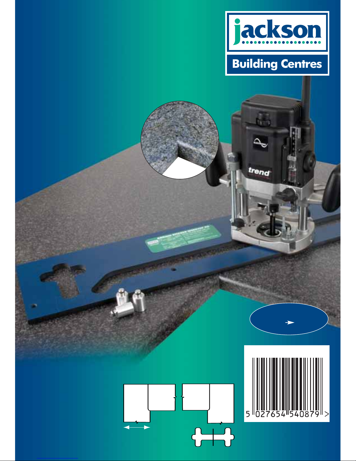
Made from durable
10mm thick phenolic.
WORKTOP WIDTH
600mm 616mm
Router & worktop not included.
KITCHEN
WORKTOP JIG
600mm
FOR JOINING KITCHEN WORKTOPS
WITH A ROUTER
600mm - 616mm
JOINT
INCLUDES:
3xSetting Bushes
1xInstruction Manual
REQUIRES:
12.7mm (1/2”) Collet Plunge Router
12.7mm (1/2”) x 50mm TCT Router Cutter
Ref. 3/83DX1/2TC
30mm Guide Bush
Ref. GB30
Universal Sub-base for Guide Bush
Ref. UNIBASE*
Two 100mm (4”) Throat Clamps Ref.
FC/200
Panel Butt Connectors
Ref. PC/10/M
JBC/KWJ600
www.jacksonbc.co.uk
*For certain makes & models of router
Page 2

-1-
INTRODUCTION
Your new Jackson Building Centres worktop jig
will more than satisfy your expectations. It has
been manufactured under stringent Quality
Standards to meet superior performance criteria.
CAUTION: Carefully read through this entire
Instruction Manual before using your new jig.
Take special care to heed the warning symbols.
TECHNICAL DATA
Jig thickness 10mm
Cutter size 12.7mm
Workpiece thickness max. 45mm
Worktop width: min. 600mm
max. 616mm
Guide bush size 30mm
Weight 6.1kg
CONTENTS
TECHNICAL DATA _____________________1
SAFETY ____________________________2-3
ITEMS ENCLOSED ____________________4
DESCRIPTION OF PARTS_______________4
ACCESSORIES
– Recommended Cutters ________________5
– Sub-base Set ________________________5
– Panel Butt Connector Bolts _____________6
– Biscuit Jointer for the Router ____________6
– Flat Biscuit Dowels____________________6
– Clamp ______________________________6
ASSEMBLY
– Location Bush Identification _____________7
– Margin Distance ______________________7
– Setting out the Joints __________________7
OPERATION
– Setting the Length Stop _______________ 8
– Female Joint_________________________8
– Male Joint___________________________9
– Cutting the Bolt Recesses _____________10
– Strengthening the Joint _______________11
– Sealing the Joint ____________________11
SPARE PART ________________________11
MAINTENANCE ______________________11
ENVIRONMENTAL PROTECTION________11
TROUBLESHOOTING _________________12
GUARANTEE ________________________IB
The following symbols are used throughout this
manual:
Denotes risk of personal injury, loss of
life or damage to the tool in case of nonobservance of the instructions in this
manual.
Refer to the instruction manual of
your power tool.
This unit must not be put into service until it has
been established that the power tool to be
connected to this unit is in compliance with
98/37/EC (identified by the CE marking on the
power tool).
INTENDED USE
This jig is intended for use with a plunge router
with suitable guide bush and router cutter fitted
to rout a kitchen worktop joint in laminate
covered particle board.
Page 3

-2-
SAFETY
WARNING:
Observe the safety regulations in the
instruction manual of the power tool to be
used. Please read the following
instructions carefully. Failure to do so
could lead to serious injury. When using
electric tools, basic safety precautions,
including the following should always be
followed to reduce the risk of fire, electric
shock and personal injury. Also observe
any applicable additional safety rules.
Read the following safety instructions
before attempting to operate this product.
PLEASE KEEP THESE
INSTRUCTIONS IN A SAFE PLACE.
The attention of UK users is drawn to The
Provision and Use of Work Equipment
Regulations 1998, and any subsequent
amendments.
Users should also read the HSE/HSC
Safe Use of Woodworking Machinery
Approved Code of Practice and Guidance
Document and any amendments.
Users must be competent before using
our products.
IMPORTANT NOTE:
Residual Risk. Although the safety
instructions and operating manuals for
our tools contain extensive instructions on
safe working with power tools, every
power tool involves a certain residual risk
which cannot be completely excluded by
safety mechanisms. Power tools must
therefore always be operated with
caution!
General
1. Disconnect power tool when making
any adjustments. When not in use,
before servicing and when changing
accessories such as cutters,
disconnect power tool and attachment
from power supply. Ensure the
machine is switched off before
plugging tool in or connecting to a
power supply.
2. Always mount the power tool,
accessory or attachment in conformity
with the present instructions. The tool
should not be modified or used for any
application other than that for which it
was designed.
3. Keep children and visitors away. Do
not let children or visitors touch the
tool, accessory or attachment. Keep
children and visitors away from work
area. Make the workshop child proof
with padlock and master switch.
4. Dress properly. Do not wear loose
clothing or jewellry, they can be
caught in moving parts. Rubber
gloves and non-skid footwear is
recommended when working
outdoors. Wear protective hair
covering to contain long hair.
5. Consider working environment. Do
not use the product in the rain or in a
damp environment. Keep work area
well lit. Do not use power tools near
gasoline or flammable liquids. Keep
workshop at a comfortable
temperature so your hands are not
cold. Connect machines that are used
in the open via a residual current
device (RCD) with an actuation
current of 30 mA maximum. Use only
extension cables that are approved for
outdoor use.
6. The accessory or attachment must be
kept level and stable at all times.
7. Keep work area clean. Cluttered
workshops and benches can cause
injuries. Ensure there is sufficient
room to work safely.
8. Use the attachment with the power
tools and accessories specified in this
manual only. Do not force the tool or
attachment to do a job for which it is
not designed.
9. Secure idle tools. When not in use,
tools should be stored in a dry and
high or locked up place, out of reach
of children.
10. For best control and safety use both
hands on the power tool and
attachment. Keep both hands away
from cutting area. Always wait for the
spindle and cutter to stop rotating
before making any adjustments.
11. Always keep guards in place and in
good working order.
12. Remove any nails, staples and other
metal parts from the workpiece.
13. Maintain tools and cutters with care.
Keep cutters sharp and clean for
better and safer performance. Do not
use damaged cutters. Follow
instructions for lubricating and
changing accessories. Keep handles
dry, clean and free from oil and
grease.
14. Maintain accessories. Do not use
damaged accessories. Only use
accessories recommended by the
manufacturer.
15. Check damaged parts. Before
operation inspect the attachment, the
power tool, the cable, extension cable
and the plug carefully for signs of
damage. Check for alignment of
moving parts, binding, breakage,
mounting and any other conditions
that may effect its operation. Have
any damage repaired by an
Authorised Service Agent before using
the tool or accessory. Protect tools
from impact and shock.
16. Do not use tool if switch does not turn
it on or off. Have defective switches
replaced by an Authorised Service
Agent.
17. Don't over reach. Keep proper
footing and balance at all times. Do
not use awkward or uncomfortable
hand positions.
18. Don’t abuse the cable. Never carry
power tool or accessory by cord or
pull it to disconnect from the socket.
Keep cord from heat, oil and sharp
edges. Always trail the power cord
away from the work area.
19. Connect dust extraction equipment.
If devices are provided for the
connection of dust extraction and
collection facilities, ensure these are
connected and properly used.
20. Check all fixing and fastening nuts,
bolts and screws on power tool,
attachment and cutting tools before
use to ensure they are tight and
secure. Periodically check when
machining over long periods.
21. Stay alert. Watch what you are
doing. Use common sense. Do not
operate tools when you are tired,
under the influence of drugs or
alcohol.
22. Personal Protective Equipment
(PPE). All PPE must meet current
UK and EU legislation.
23. Do not leave tools running
unattended. Do not leave tool until it
comes to a complete stop.
24. Always clamp workpiece being
machined securely.
25. Only use cutting tools for
woodworking that meet EN847-1/2
safety standards, and any
subsequent amendments.
26. Vibration levels. Hand held power
tools produce different vibration
levels. You should always refer to the
specifications and relevant Health &
Safety Guide.
Routing Safety
1. Disconnect router power tool. When
not in use, before servicing and when
changing accessories such as
cutters, disconnect router and
attachment from power supply.
2. Ensure router cutter has stopped
rotating before changing it. Never
use the spindle lock as a brake.
3. Remove adjusting keys and
spanners. Form the habit of checking
to see that keys and adjusting
spanners are removed from the
router tool, cutter and attachment
before turning router on. Make sure
cutter can rotate freely.
4. Noise. Take appropriate measures
for the protection of hearing if the
sound pressure of 85dB(A) is
Page 4

-3-
exceeded. Routing sound pressure
may exceed 85dB(A), so ear
protection must be worn.
5. Eye protection. Wear safety goggles,
spectacles or visors to protect the
eyes from ejected waster particles.
6. Respiratory protection. Wear a face
or dust mask, or powered respirator.
Dust masks/filters should be changed
regularly.
7. Do not switch router on with the cutter
touching the workpiece.
8. The direction of routing must always
be opposite to the cutter's direction of
rotation. Do not back-cut or climb-cut.
9. At the end of the cut, release the
router plunge and allow spindle to
stop rotating before putting machine
down.
10. Check before cutting that there are no
obstructions in the path of the router.
When cutting through the full
thickness of the workpiece, ensure
there are no obstacles beneath
workpiece, and that a sacrificial work
surface is used.
Router Cutter Safety
1. Cutting tools are sharp. Care should
be taken when handling them.
2. Always use cutters with a shank
diameter corresponding to the size of
the collet installed in your tool.
3. Always run router cutters at the
spindle speed recommended and
marked accordingly. Ensure cutter
has reached correct speed before
entering workpiece. Recommended
speeds can be found on the
packaging, in cutter instructions, in the
Trend Routing Catalogue or on our
website.
4. Always use router cutters in a router.
Router cutters must not be used in a
drill. Drill and boring bits must not be
used in a router. Router cutters must
only be used for the material cutting
application for which they are
designed. Do not use on metal or
masonry.
5. Never use cutters with a diameter
exceeding the maximum diameter
indicated in the technical data of the
powertool or attachment used.
6. Do not drop cutters or knock them
against hard objects. Do not use
cutters that are damaged.
7. Cutters should be kept clean. Resin
build up should be removed at regular
intervals with Resin Cleaner
®
. The
use of a dry lubricant (Trendicote
®
PTFE) will act as a preventative. Do
not use PTFE spray on plastic parts.
8. When using stacked tooling (multi-
blade, block and groover etc.) on a
spindle arbor, ensure that the cutting
edges are staggered to each other to
reduce the cutting impact.
9. Cutter shanks should be inserted into
the collet to the line indicated on the
shank. This ensures that at least
3
⁄
4
of the shank length is held in the
collet. Do not over-tighten the collet
nut as this will score the shank and
create a weakness and fracture point.
10. Observe the correct assembly
instructions in the router instruction
manual for fitting the collet and nut.
Observe the router power tool manual
instructions on fitting cutters correctly.
11. It is advisable to periodically check
the collet and collet nut. A worn,
distorted or damaged collet can cause
vibration and damage the shank, and
should be replaced. Worn collet nuts
should be replaced.
12. Do not take deep cuts in one pass;
take several shallow or light passes to
reduce the side load applied to the
cutter. Too deep a cut in one pass can
stall the router.
13. Very small diameter cutters must be
handled and used with care.
14. Always return cutter to its packaging
after use.
15. Should you experience excessive
vibration during use stop immediately.
Have the eccentricity of the router,
router cutter and clamping system
checked by a qualified repair agent.
16. All fastening screws and nuts should
be tightened using the appropriate
spanner or key in accordance with the
manufacturers instructions.
Using Routers In A Fixed Position
1. Attention should be made to the
HSE’s Safe Use of Vertical Spindle
Moulding Machines Information Sheet
No.18 and any revisions.
2. After work, release the router plunge
to protect the cutter.
3. Always use a push-stick or push-block
when making any cut less than
300mm in length or when feeding the
last 300mm of the cut.
4. The opening around the cutter should
be reduced to a minimum using
suitably sized insert rings in the table
and closing the back fence cheeks or
fitting a false fence on the back fence.
5. Whenever possible use a work
holding device or jig to secure
component being machined.
6. Ensure attachment is securely fitted to
the workbench, with table surface at
approximately hip height.
7. Ensure a No-Volt Release Switch is
fixed to or adjacent to the attachment,
is easily accessible and that it is used
correctly.
8. In router table (inverted) mode, stand
to the front right of the table. The
cutter will rotate anti-clockwise when
viewed from top so the feed direction
is from the right (against the rotation
of the cutter).
9. In overhead mode, stand to the front
left of the machine table and the feed
direction is from the left.
10. Do not reach underneath table or put
your hands or fingers at any time in
the cutting path while tool is
connected to a power supply.
11. Never thickness timber between the
back of the cutter and the backfence.
Useful Advice When Routing
1. Judge your feed rate by the sound of
the motor. Feed the router at a
constant feed rate. Too slow a feed
rate will result in burning.
2. Take many light passes rather than
one deep cut to reduce the side load
applied to both router and router
cutter.
3. Trial cuts should be made on waste
material before starting any project.
4. When using some attachments
including a router table or dovetail jig,
the use of a fine height adjuster is
highly recommended.
5. When using a template guide bush,
ensure there is sufficient clearance
between cutter tip and inside edge of
bush and that it cannot come into
contact with collet and nut. Ensure
cutter and guide bush are concentric.
Router Cutter Maintenance
1. Composite cutting tools (brazed tip)
must be maintained by a competent
person i.e. a person of training and
experience, who has knowledge of
the design requirements and
understands the levels of safety to be
achieved.
2. The design of composite tools must
not be changed in the process of
maintenance. When re-grinding the
tool, care must be taken not to cause
weakening of the body or the
connection between the cutting edge
and the body.
3. Replacement parts must meet Trend
specification.
4. Tolerances which ensure correct
clamping by the collet shall be
maintained.
Version 6.0 05/2005
Page 5
-4-
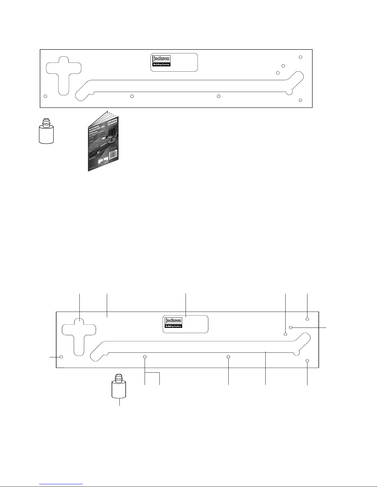
ITEMS ENCLOSED
DESCRIPTION OF PARTS
x1
x1
x3
ai
j
b
e g
g
f
c
ddh
h
&
Jig body
Label
Postform joint slot
Female joint bush location hole
Length setting stop location hole 600mm
a
b
c
d
e
Length setting stop location hole 616mm
Male joint bush location hole
Bolt recess bush location hole
Connecting bolt recess slot
Alloy location bush
f
g
h
i
j
ITEMS REQUIRED
■ 1/2” plunge router.
■ 30mm guide bush.
■ 12.7mm diameter x 50mm cut
router cutter with 1/2” shank.
■ 2 x trestles.
■ 2 x clamps.
■ Hand tools.
■ Panel connector bolts.
■ Wooden biscuits Size No.20.
■ Sealant.
Page 6

-5-
Recommended Cutters
Ref. 3/83DX1/2TC, 3/83X1/2TC,
C153DX1/2TC, C153X1/2TC
A 12.7mm (1/2”) diameter cutter must be used, which
has a 50mm cutting reach and plunge cut facility.
Router must be plunged in stages of maximum 8mm
in one pass.
Sub-base Set
Ref. UNIBASE
To obtain a perfect accurate close fitting joint, a
30mm guide bush must be used. The guide bush
must always be fitted concentric with the cutter.
This can be achieved using a Universal Sub-base
and 30mm outside diameter guide bush Ref. GB30.
The Universal Sub-base has a central recess to
allow fitting of the guide bush to most makes of
routers and is available ready to fit the most
popular makes.
The Sub-base contains screws, a line up bush and
two line up pins. The line up pins and bush ensure
exact alignment of the Sub-base with router
spindle, when fitted with the relevant collet.
ACCESSORIES
Products available from your local store where
you bought the jig.
UNIBASE
Fits following Router Models
Atlas Copco OFSE2000 Bosch GOF 1300ACE, 1600A,
1700ACE Casals FT2000VCE CMT CMT1E DeWalt
DW625EK, 629 Draper R1900V Elu MOF 31, 77, 98,
131, 177(E) Felisatti TP246(E), R346EC Festo OF2000E
Freud FT2000E Hitachi M12V, M12SA, TR12 Makita
3612BR, 3612(C) Metabo OF1612, OFE1812 Ryobi
RE600N, R600N, RE601, R500, R502 Skil 1875U1
Wadkin R500
General instructions for fitting
Sub-bases to Router
1. Fit line up guide bush onto sub-base, with
screws supplied.
2. Fit 12.7mm (
1
/2”) shank line up pin into collet
of router. Plunge router until pin projects
through base and lock plunge.
3. Locate guide bush and sub-base assembly
over protruding pin.
4. Line up fixing holes and fit screws.
5. Now tighten up screws.
6. Remove line up bush and line up pin.
Alignment should now be correct. Fit 30mm
guide bush and cutter.
7. Periodically check the sub-base is concentric
to the spindle of the router.
t
r
e
n
d
3
0
m
m
R
30mm Guide Bush
Ref. GB30
Page 7

-6-
100mm (4”) min.
throat depth
Panel Butt Connector Bolts
Ref. PC/10/M (
Pack of ten)
Panel butt connectors are essential for
connecting worktops. They fit into the recess on
the underside of the worktop and are tightened
with a 10mm spanner. The jig has integral bolt
recess slots to allow the bolt recess to be cut in
the underside of the worktop, using cutter. The
recess is elongated to allow easy access for the
spanner.
Biscuit Jointer for the Router
Ref. 342X1/2TC, C152X1/2TC
Worktops with inadequate support below them
need additional stability by biscuit jointing the
edges. The biscuit jointing set for the router
together with the No.20 biscuits will ensure
worktops do not sag or warp in time.
Flat Biscuit Dowels
Ref. BSC/20/100 (Pack of 100 biscuits)
Biscuits are used to strengthen the joint. When
used with PVA glue they expand ensuring a tight
joint.
Whenever clamps are used, ensure
they do not foul the router path and
that they are securely tightened.
Clamp
Ref. FC/200
Two heavy duty quick action or gripper clamps
with throats of at least 100mm (4”) are required
to secure the jig to the worktop.
No.20
Page 8

-7-
ASSEMBLY
Location Bush Identification
Three location bushes are used in different holes
in the jig to align the correct template aperture
for the application.
Setting out the Joints
When cutting a joint ensure location bushes
contact the postformed edge of the worktop. For
certain joints the worktop will need to be inverted
so that all cuts are made into the postformed
edge, never out through it. When routing worktop
the balancing paper on the underside may feather
edge – this feather edge should be removed with
abrasive paper.
Location bushes are held in position by ‘O’ rings.
Insert the smallest end of the bush into the hole
by lightly pushing and turning at the same time.
If the bushes are tight use a lubricant on the ‘O’
ring. Ensure bushes are fully home before use.
When using jig ensure location bushes do not
foul workbench.
28mm
In order to prevent breakout of the
laminate, rotation of the cutter and
feed direction must always be into the
postform edge of the worktop.
Margin Distance
Allow 8.5mm when cutting joints. Measure or
use a batten of this thickness to aid setting out.
Plan view
of joints
Length stop holes
Female holes
O ring
Location
bush
Cutter
Sub base
Guide bush
30mm Ø
Location
bush
Worktop
Template
8.5mm
Right hand joint
Male
Female
Male
Female
Cut male with laminate down
Cut female with laminate up
Postform edge
The joint takes up 28mm, this should
be allowed for with extra material in the
length of the male worktop.
Male
Female
Postform edge
PENINSULAR
Postform edge
Postform edge
Male
Female
Left hand joint
Cut male with laminate up
Cut female with laminate down
Bolt recess hole
Male holes
Male holes
Page 9

-8-
Routing the female part of the Joint
OPERATION
Setting the Length Stop for the
Female Cut
Carry out the setting operation first:
■ With the label side uppermost fit the length
stop bush in one of the two holes
depending on the width of the worktop. If
worktop is not 600mm or 616mm, a
packing piece, or a new hole to correct
position will suffice.
Location bushes
in female hole
Quick action
clamp here
Length
stop bush
Router feed
direction
600mm
616mm
Female Joint
■ Fit two location bushes in female holes as
shown. (The label must be uppermost.)
Leave the length stop bush in position.
■ Place the template onto the worktop to be
cut, ensuring the location bushes are
touching the worktop. Now cramp securely
in position using two quick action clamps
(with minimum of 100mm throat) ensuring
they will not foul the router path.
■ Set cutter depth.
■ Plunge router and cut joint in a series of
passes, feeding left to right. At end of each
cut release plunge.
When cutting a joint, hold the router
guide bush hard against the template
and cut from left to right. It is
recommended that the depth stops of
the router are used to set the depths
of cut. Several shallow passes of the
router should be made and it is not
necessary to lean heavily on the
router or the jig. Allow the weight of
the router to rest on the part of the
template which is resting on the
worktop. Ensure router remains
parallel and upright at all times.
Postform
edge
The edge of the jig slot that is not
used is notched to act as a visual
guide.
Release plunge on router at end of
each cut.
Ensure the router base will slide freely
over the label. The label can be
removed if necessary.
Page 10

-9-
Male Joint
Depending on accessibility lay female worktop
into position on units. Lay male worktop on top
and support other end. Using a pencil draw
round the female cut onto the male from
underside. If inaccessible lay female onto male.
Depending on a right or left hand joint, the pencil
line may need to be transferred on to the other
side. Due to the difference between the cutter
and the guide bush diameters, the cutter path
will be 8.5mm over from the edge of the
template, therefore either measure 8.5mm or
use a packing piece of this size to offset the
template by this amount to ensure the cutter cuts
along the pencil line.
The postformed edge of the worktop must
always be in contact with the location bushes,
this means that to cut a male right hand joint, the
worktop must be inverted. Remembering to cut
into the postformed edge.
■ Insert two location bushes into male holes as
shown, label facing down.
■ Place template across the width of the
worktop and clamp securely to worktop.
■ Set cutter depth. Plunge router and cut the
male joint before finally cutting the work-top to
length. A series of passes should be made
feeding from left to right. At end of each cut
release plunge.
Routing the male part of the Joint
Quick action
clamp here
Direction of
router travel
Location bush in
male hole
Postform edge
Test fit the joints together, abrasive
paper may be required to clean up the
chipboard core.
Ensure the router base plate will not
foul the clamp.
Page 11

-10-
Cutting the Bolt Recesses
When the joint has been tested, proceed as
follows to cut the recess for panel butt
connectors bolt on the underside of the worktop.
The same cutter and guide bush are retained
and used with the integral bolt recess slots in the
jig to produce the recesses for the panel butt
connectors. The bolt recess position can be
gauged approximately 150mm from the edge of
the postform edge, or where access is possible
with kitchen units. Mark with pencil both
positions on the underside of the worktop.
Insert the location bushes into the bolt recess
holes as shown.
■ The template may need to be inverted
when cutting some bolt recesses.
■ Securely clamp jig to worktop.
■ The bolt recesses should be
approximately 20mm deep although
this will depend upon the thickness
of worktop.
■ Once one bolt recess is cut move jig
over to the remaining pencil lines and repeat.
■ Repeat the procedure for the male joint.
Routing the bolt recess in the
female part of the joint
Quick action
clamp here
150mm
Location bushes in
bolt recess hole
Pencil mark
Direction of
router travel
Worktop Recess
Thickness Depth
30 22mm
40 28mm
Routing the bolt recess in the
male part of the joint
150mm
Location bushes in
bolt recess hole
Pencil mark
Direction of
router travel
Quick action
clamp here
Underside of
worktop
Postform edge
Underside of worktop
Best results are achieved when the
centre line of the bolt corresponds to
the centre line of the worktop. Clamp
jig securely to worktop.
Page 12

-11-
Strengthening the Joint
If the joint between the worktops is not
supported underneath, after some time the joint
may ‘sag’ and become misaligned; to reduce this
the joint should be reinforced with a loose
tongue or biscuit dowels. The biscuit jointing
cutter set can be used with a portable router.
The size of biscuit used should be No. 20.
Ref. BSC/20/100 (100 biscuits)
A 600mm worktop should have at least 5
biscuits.
Sealing the Joint
The cut edges of the joint should be coated with
a water-resistant adhesive, or sealant before
assembly, to prevent moisture seeping into the
core of the worktops, which would swell, and
disfigure the worktop
No.20
PVA
SEALANT
Waterproof
Biscuit
Underside View
SPARE PART
Replacement pack of three
alloy location bushes.
Ref. JBC/KWJ/BPK
MAINTENANCE
The jig has been designed to operate over a long
period of time with a minimum of maintenance.
Continual satisfactory operation depends upon
proper tool care and regular cleaning.
Cleaning
■ Regularly clean the jig with a soft cloth.
Lubrication
■ Your jig requires no additional lubrication.
ENVIRONMENTAL PROTECTION
Recycle raw materials instead of disposing as
waste.
Packaging should be sorted for environmentalfriendly recycling.
The product and its accessories at the end of their
life should be sorted for environmental friendly
recycling.
Page 13

-12-
Fault Cause Remedy
■ Joint does not fit correctly Cutter or guide bush is the Check concentricity of cutter
at the radius. incorrect diameter or location with guide bush. Cutter 12.7mm
bushes are not against diameter with 30mm diameter
worktop edge. guide bush. Ensure location
bushes touch worktop.
■ The back edge of the joint Either the length stop or Check position of length stop
does not line up. template was in the incorrect and re-cut joints.
position, or the worktop has
not pushed up against the
length stop when the joint
was cut.
■ When clamped together the The guide bush has drifted away Check with a straight edge
joint has irregular gaps. from the edge of the template which part of the joint is uneven
whilst cutting either part of the and re-cut (this can only be
joint, or wood chips in particle done on the male cut) ensuring
board have torn slightly. that the guide bush is kept
against the template by
machining from left to right. Use
abrasive paper to remove torn
wood chips.
■ Chipped laminate Can be caused by a blunt cutter Always use sharp cutters and
or removing too much material when cutting through the
at one pass or exiting out of laminate cut 3–4mm of material.
postform edge. Maintain correct feed direction,
to ensure cutter enters
postform edge.
■ Jig slipping on material Clamps not secure or too deep Check clamps for wear. Clamp
a cut being made or cutter is securely, take shallow passes,
blunt. use a sharp cutter.
■ Cut joints not square Router has tilted or operator Ensure jig is supported and do
has leaned heavily on router not push hard on router taking
causing jig flex. shallow passes. Ensure weight
of router is on supported part
of jig and that the router is
upright.
■ Assembled joint not flush Worktop different thickness or Ensure worktop is same
or bowed worktop not flat (cupped). thickness and flat.
TROUBLE SHOOTING
Page 14

IB
GUARANTEE
1. This product has been manufactured to a high quality standard. It is guaranteed against faulty
materials and workmanship for 12 months from purchase. Please retain your till receipt as proof of
purchase.
2. If the product is found to be defective within the relevant time period, we will either replace all
defective parts or, at our discretion, replace the unit free of charge with the same item or items of a
greater value and/or specification.
3. This guarantee does not cover defects caused by or resulting from:
(a) Misuse, abuse or neglect
(b) Professional or hire use
(c) Or damage caused by foreign objects, substances or accident.
4. In the unlikely event that this product does develop a fault please contact the store that you
purchased the jig from.
5. This guarantee is offered in addition to and does not effect your statutory rights, which may
additionally enable you to cancel the contract. The warranty is only valid within the UK
© Copyright 2005. No part of this publication may be reproduced, stored or transmitted in any form without prior permission. Our policy
of continuous improvement means that specifications may change without notice. Jackson Building Centres cannot be held liable for
any material rendered unusable or any form of consequential loss. E&OE
MANU/JBC600 v1.0
Page 15

RECYCLABLE
HEAD OFFICE
Pelham House, Canwick Road
Lincolnshire, LN5 8HG
Telephone 01522 511 115
www.jacksonbc.co.uk
 Loading...