

Page 1
IR Preheater Set
Ref. PHS-KC
INSTRUCTION MANUAL
www.jbctools.com
Page 2
2
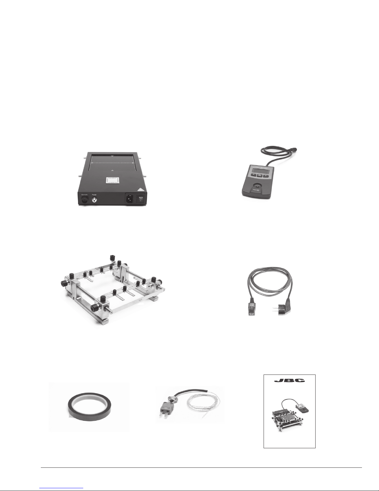
Packing List
The following items should be included:
Power Cord .............................................. 1 unit
Ref. 0009417 (100V/120V)
0009401 (230V)
Thermocouple .............. 1 unit
Ref. PH218
Kapton Tape .................. 1 unit
Ref. PH217
Manual ............................ 1 unit
Ref. 0018633
Ref. PHS-KC
IR Preheater Set
Convection Preheater Support ........... 1 unit
Ref. PHS-SA
Heater Unit Console
IR Preheater ............................................................................................................................................... 1 unit
Ref. PHS-1C (120V)
PHS-2C (230V)
PHS-9C (100V)
INSTRUCTION MANUAL
www.jbctools.com
Page 3
3
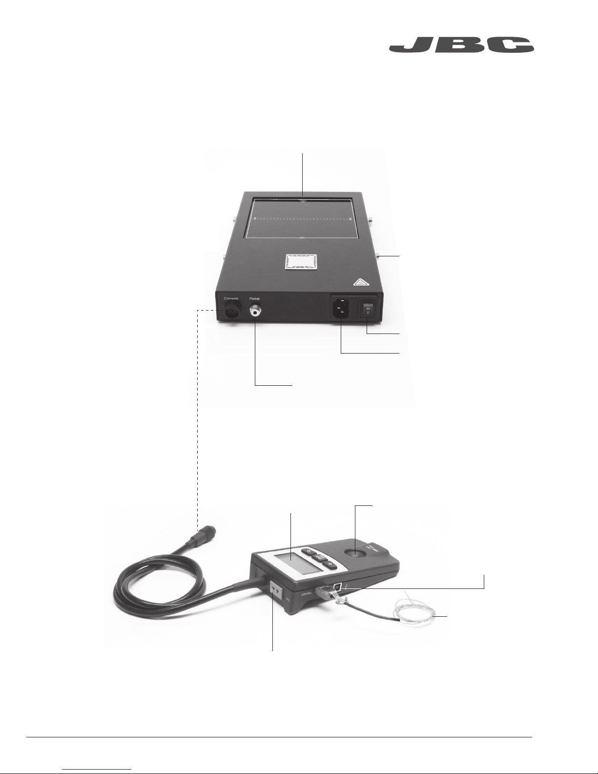
Features
Pedal socket (optional)
Ref. P-005
Heating Areas
Power socket
Power
Fixing brackets for
PHS-SA Convection
Preheater Support
Heater Unit
Console
Control Unit Start / Stop
Auxiliary Thermocouple (Type K) Input
Thermocouple
(Type K)
Ref. PH218
USB-B
connector to PC:
Update software
Zone A
Zone B
www.jbctools.com
Page 4
4
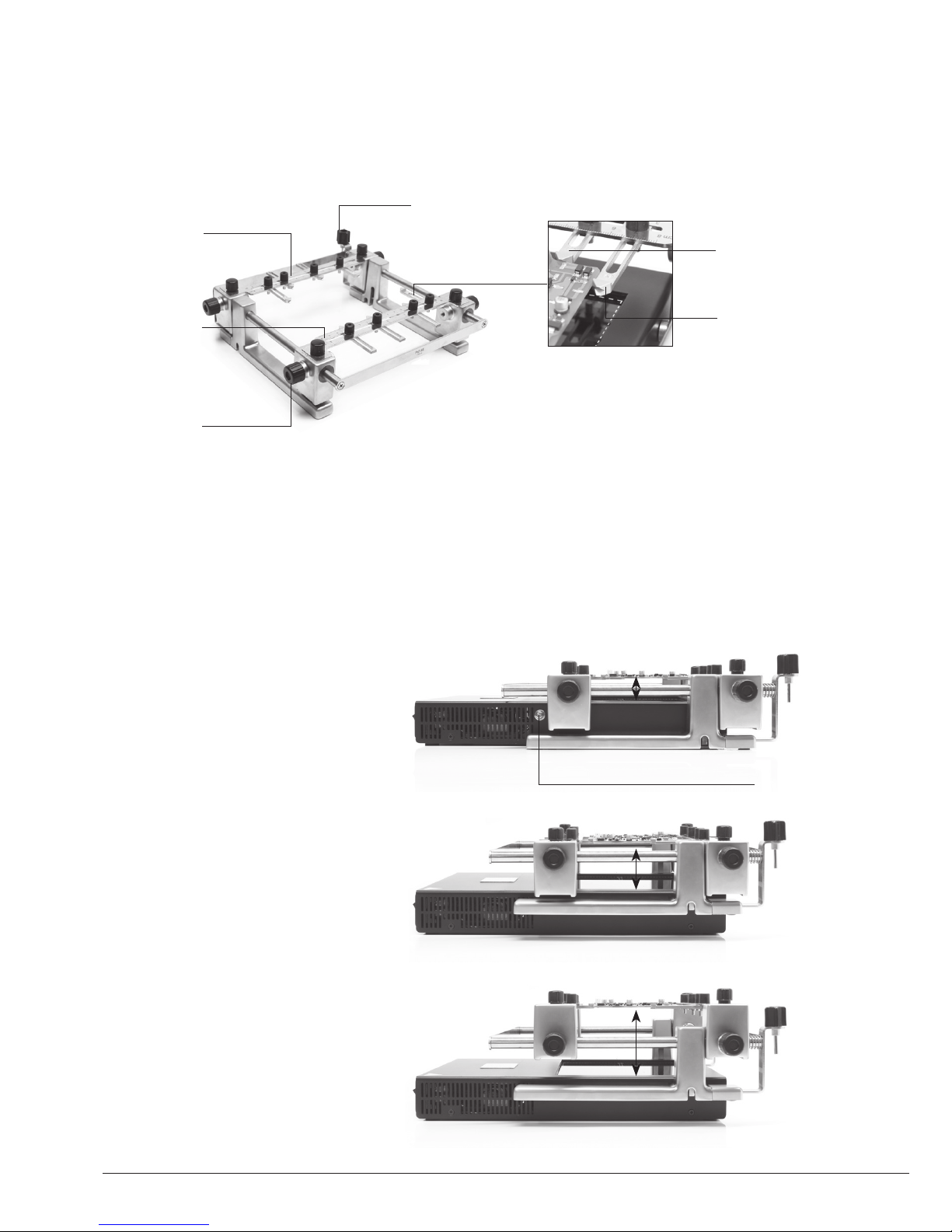
For PCBs of 0.8 - 2.4mm thick
For PCBs of 2.4 - 6mm thick
28mm
50mm
For PCBs over 6mm thick
70mm
Remove these knobs if necessary
It allows adjustment for 3 heights between the PCB and the Heating Area of the PHS-B Heater Unit.
Low level
High level
Medium level
PHS-SA Features
Clamp knobs
Sliding guide
Spring guide
Allen key
Height Adjustment
For fixing irregular
shaped PCBs to
the support.
For fixing identical
PCBs in the same
position.
Slot clamps
Page 5
5
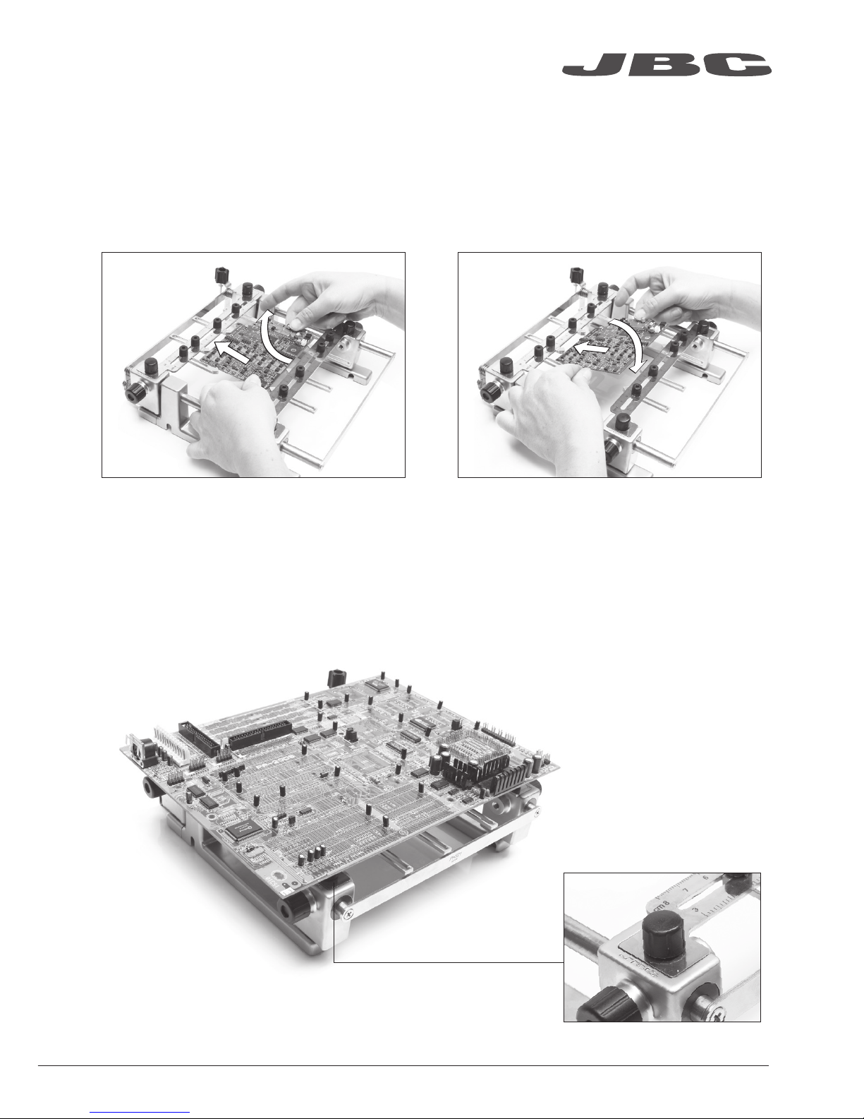
After loosening the SP guide knobs, push the
PCB against the SP guide and lift out.
Place large PCBs on
the 4 rubber cups
Push the PCB against the SP guide, position it
and tighten the SP guide knobs.
Changing PCBs of the same batch
The support lets you place PCBs of the same batch so as to always heat the same area.
Use the sliding guides to change the PCBs.
Removing the PCB
Placing another PCB
Reworking large PCBs
www.jbctools.com
Page 6

Positioning PHS on RWS
Fit the positioning cap into
the positioning bolt.
The four corner guides helps
to the placement of the Unit.
Positioning Cap
Positioning Bolt.
It can be removed with a
screwdriver if fixed position is
not wanted.
The position of the PHS can be fixed on the RWS by means of positioning caps.
There are two possible PHS position.
6
Page 7

Notes
7
www.jbctools.com
Page 8

8
Profiles by Temperature
The usual way to run a profile is using the Thermocouple (TC) connected to the Control Input of the
console. JBC offers 3 predefined profiles (JBCset) and 10 profiles ready for you to personalize.
Why Infrared? The most efficient technology for PCB preheating
This is the most advanced, efficient and cost-effective method to preheat PCBs in any soldering job
or rework job. The low thermal mass of the infrared element gives outstanding control of the heat
output and the process temperature. This technology provides fast response, high heating rates and
uniform heating that ensure the best results.
Operation
JBCset profiles
There are 3 profiles predefined by JBC: A, B and C. The difference between them is the number
of steps: 2, 3 or 4. The thicker your PCB is and the more layers it contains, the more steps are
needed to obtain a gradual warming.
These profiles are not modifiable but they can be used as a template to create your own profiles.
JBCset A
2 steps
JBCset B
3 steps
JBCset C
4 steps
For repetitive jobs we recommend running profiles without the Thermocouple (TC). Once any
profile has been run to the end, the system has all the process data which you can save.
Once it is saved, you can run this profile without connecting the Thermocouple (TC). The heating
process will the same as long as the same working conditions are respected.
User profiles
You can create your own profiles from the JBCset profiles. On the work screen of the profile,
press the Enter button and choose the option Edit profile.
Power Mode
The unit works at the selected power or temperature during the defined time. These parameters can
be modified from the work screen by pressing the Enter button and the Edit parameters menu.
To see the current temperature you must plug the Thermocouple (TC) into the Control connector.
PCB reference
specifications:
FR4 1,6mm thick
and 2 layers.
FR4 2,2mm thick
and 6 layers.
FR4 1,6mm thick
and 6 layers.
Profiles set using the low position of the PHS-SA Support (28 mm in height between the PCB and the heating area).
Page 9

9
Recommended Guidelines
1. Place the Thermocouple (TC) as near as possible to the component being worked on.
2. If there are any sensitive components, use the Auxiliary Thermocouple as protection.
You can select the protection temperature in Station settings. If the selected temperature is
reached, the Heater Unit will stop the process and a warning message will be shown.
3. IPC* does not recommend exceeding ramp-up rates over 3 - 4 °C / sec (5 - 7 °F / sec) so as to
reduce the risk of thermal stress on the PCB.
* IPC was founded in the U.S. in 1957 as the Institute for Printed Circuits and is committed to becoming the
most recognized international industry association for the electronics manufacturing industry.
Fix the TC with Kapton Tape
Auxiliary Thermocouple (TC)
www.jbctools.com
Page 10

10
Display Control
Page 11

11
www.jbctools.com
Page 12

12
Maintenance
Before carrying out maintenance or storage, always allow the equipment and the support to cool.
- Check periodically that the PHS-KB is clean.
- Use a damp cloth when cleaning. Alcohol
can only be used to clean the metal parts.
- Only if it is absolutely necessary and
if cleaning with isopropyl alcohol (IPA) is not
enoug h, it is recomme nded to use a scrap er
to remove dirt in the glass area.
- Replace any defective or damaged parts.
Use original JBC spare parts only.
- Repairs should only be performed by a JBC
authorized technical service.
Clean periodically
Page 13

13
Safety
It is imperative to follow safety guidelines to protect health and prevent electric
shock, injury, fire or explosions.
- Do not use the units for any purpose other than PCB preheating. Incorrect use may cause fire.
- The mains cable must be plugged into approved bases. Make sure that it is properly grounded
before use. When unplugging it, hold the plug, not the wire.
- The temperature of accessible surfaces may remain high after the unit is turned off. Handle with care.
- Do not leave the appliance unattended when it is on.
- Do not cover the ventilation grills. Heat can cause inflamable products to ignite.
- Heat can cause inflamable products to ignite even when out of sight.
- Be careful with the remains of liquid tin. In contact with skin, it can cause burns.
- Avoid flux coming into contact with skin or eyes to prevent irritation.
- Be careful with the smoke produced when soldering.
- Keep your workplace clean and tidy. Wear appropriate protection glasses and gloves when
working to avoid personal harm.
- This appliance can be used by children over the age of eight as well as persons with reduced
physical, sensory or mental capabilities or lacking experience provided that they have been given
adequate supervision or instruction concerning use of the appliance and understand the hazards
involved. Children must not play with the appliance.
- Maintenance must not be carried out by children unless supervised.
www.jbctools.com
Page 14

14
Exploded View
Page 15

15
www.jbctools.com
Page 16

This product should not be thrown in the garbage.
In accordance with the European directive 2002/96/EC, electronic equipment at the end of their life
must be collected and returned to an authorized recycling facility.
Warranty
JBC’s 2 year warranty covers this equipment
against all manufacturing defects, including the
replacement of defective parts and labour.
Warranty does not cover product wear or misuse.
In order for the warranty to be valid, equipment
must be returned, postage paid, to the dealer
where it was purchased. Please register your
product warranty within 30 days of purchase in
www.jbctools.com/productregistration.
Manual in other languages available on our website
0022427-1018
www.jbctools.com
Specifications
IR Preheater Set
PHS-1KC / PHS-2KC / PHS-9KC
- Total weight: 4,9 kg (10.8 lb)
- Ambient operating temperature: 10 - 40 ºC (50 - 104 ºF)
PHS-1C 120V. Input 120V 50/60Hz Fuse 8A
PHS-2C 230V. Input 230V 50/60Hz Fuse 4A
PHS-9C 100V. Input 100V 50/60Hz Fuse 8A
- Weight: 2,9 kg (6.39 lb)
- Dimensions (Heater Unit): 195 x 288 x 41,5 mm (7.68 x 11.34 x 1.63 in)
- Maximum Power: 500W
- Heating Area: 65 x 135 mm (2.56 x 5.31 in - 1 zone)
130 x 135 mm (5.12 x 5.31 in - 2 zones)
- Temperature Range: 50 - 250 °C (120 - 482 ºF)
- Temperature Measurement: Thermocouple type K
- JBCset temperature profiles: 3 profiles (2, 3 or 4 steps)
- User Profiles: 20 (up to 6 steps for each)
- Maximum work time: 600 min or indefinite
PHS-SA
- Weight: 2 kg (4.4 lb)
- Dimensions (Low Position): 267 x 259 x 75 mm (10.5 x 10.2 x 3 in)
- Dimensions (High Position): 267 x 259 x 96 mm (10.5 x 10.2 x 3.8 in)
Complies with CE standards.
ESD protected housing.
 Loading...