

Page 1

Heavy Duty station
Ref. HDE-D
INSTRUCTION MANUAL
www.jbctools.com
Page 2
2
HD Purpose
Handle ............................ 1 unit
Ref. T470-FA
Manual ............................ 1 unit
Ref. 0020641
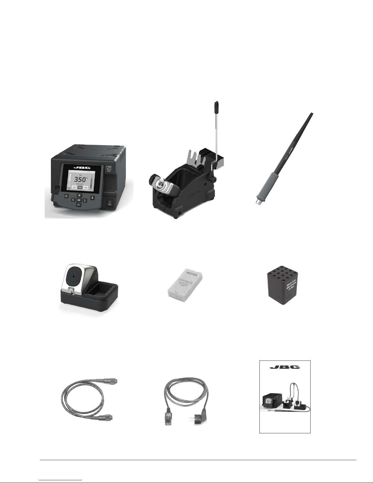
Packing List
The following items are included:
HDE Control Unit .......... 1 unit
Ref. HDE-1UD (120V)
HDE-2UD (230V)
HDE-9UD (100V)
Stand ................................ 1 unit
Ref. HD-SE
Heavy Duty station
Ref. HDE-D
Power Cord .................... 1 unit
Ref. 0010569 (230V)
0013671 (100/120V)
Stand cable ................... 1 unit
Re f. 001128 3
ESD Tip Cleaner ........... 1 unit
Ref. CL8499
Sponge ............................ 1 unit
Ref. S0354
INSTRUCTION MANUAL
Cartridge holder............. 1 unit
Ref. SCH-A
www.jbctools.com
Page 3
3
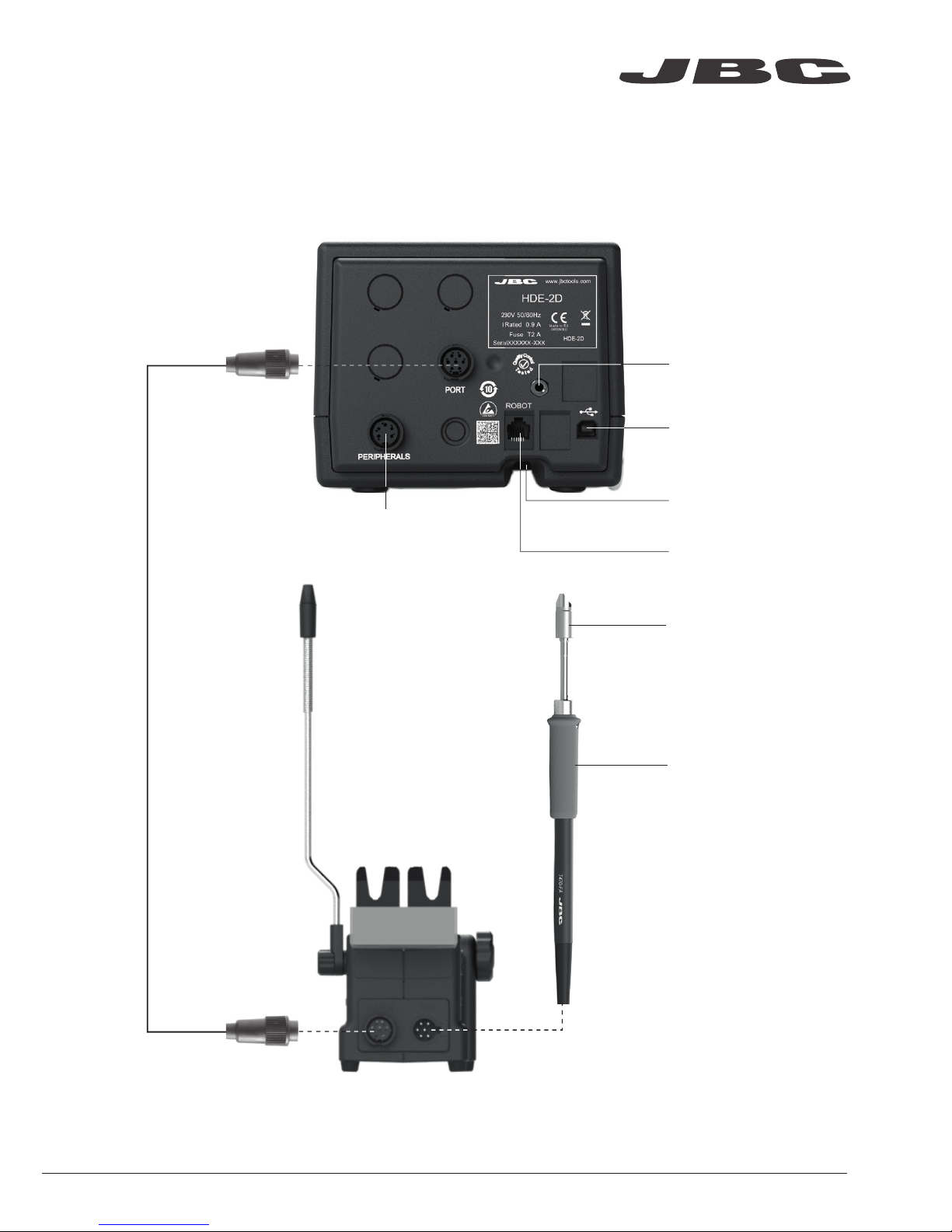
Stand
Ref. HD-SE
HDE Control Unit
RJ12 connector
for Robot system
Peripheral connector
for joining modules
and pedals
USB-B connector
Equipotential connection
Power Socket
HD Purpose
Handle
Ref. T470-FA
C470 cartridges
Required but not supplied
Stand cable
Re f. 001128 3
Connections
www.jbctools.com
Page 4
4
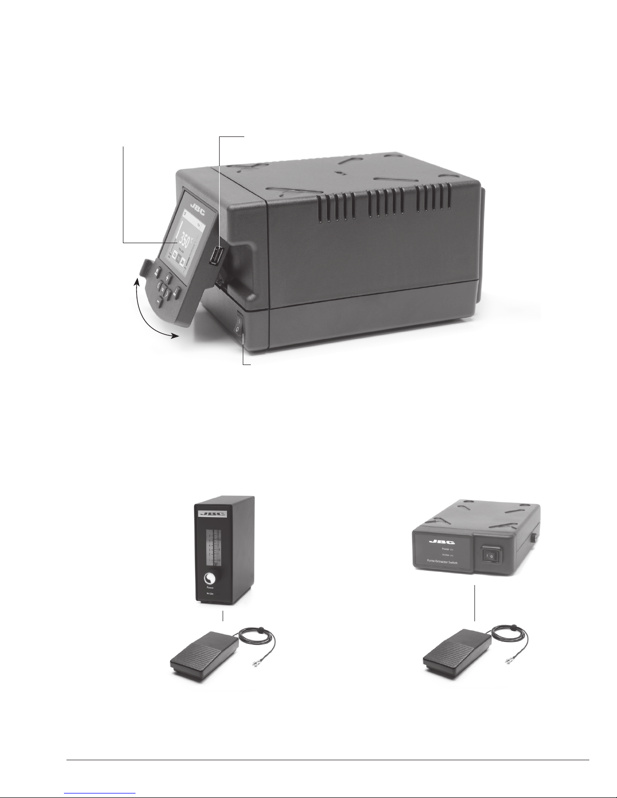
Peripherals
Join the station port with 1 module and 1 pedal. See the compatible peripherals below:
Fume
Extractor Switch
Ref. FSE-A
Nitrogen Flow
Regulator
Ref. MNE-A
Pedal
Ref. P-005
Pedal
Ref. P-005
USB-A connector
Tilt the display
for easy reading
2.8” Color TFT screen
Use this foot switch to enable/disable a module or make the tool enter/exit Sleep mode.
If you do not have a module, you can link up the P-305 Pedal Kit to the tool port.
Features
Main Switch
Page 5
380
ºC
Port
1
Power
45%
Temp. Levels
T470
250 380 400
17:14
350
ºC
Port
1
Power
45%
Temp. Levels
T470
250 350 400
17:14
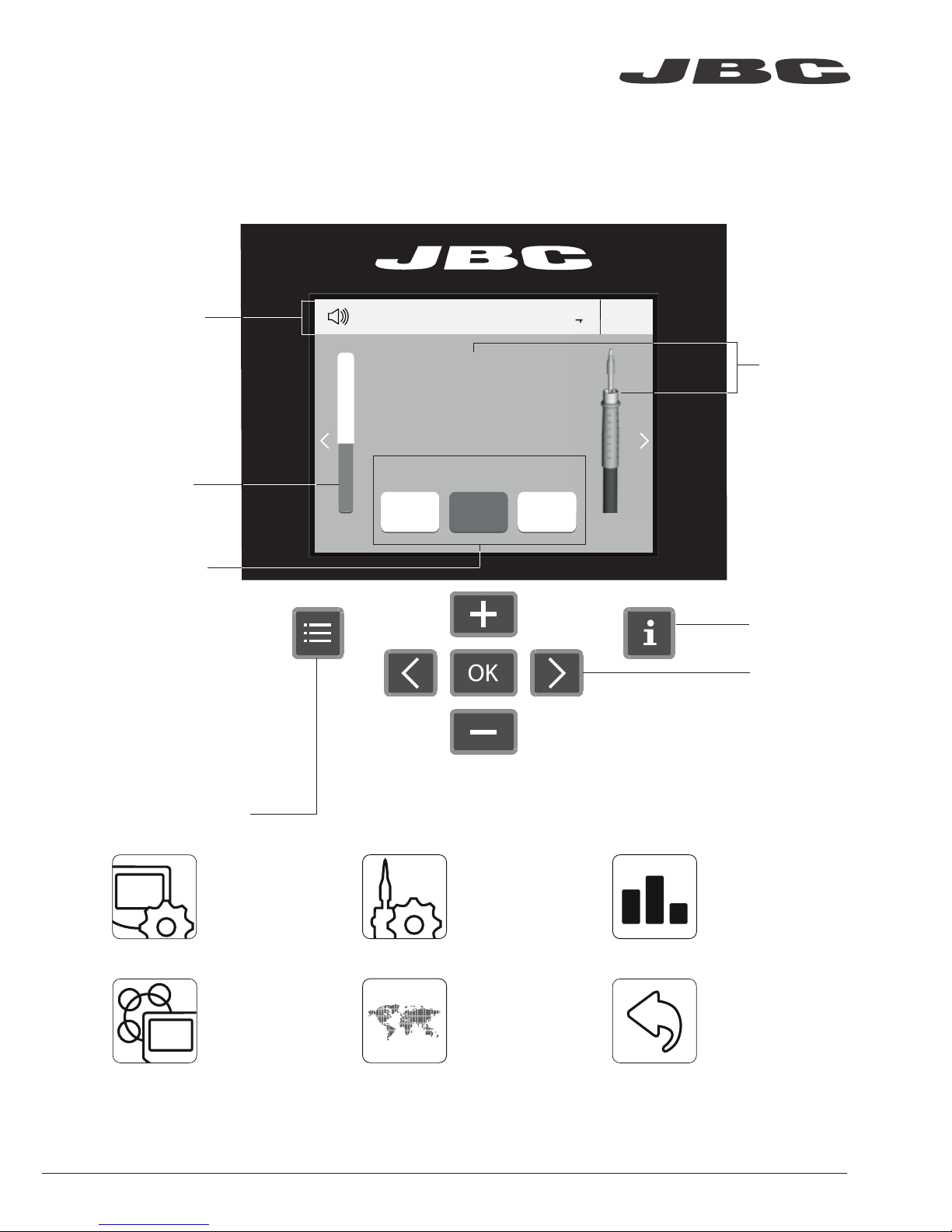
Station Tools Counters
ResetLanguagePeripherals
5
Menu Options
Station
Information
Power
indicator
Tool
in use
Work Screen
Status bar
The HDE offers an intuitive user interface which provides quick access to station parameters.
Default PIN: 0105
Change
port
Displayed if
temperature
levels are
activated
Set the station
parameters
Set the tool
parameters
Consult / modif y the
links of the peripherals
connected to the
station with the port
they are connected to.
Display the hours
worked in each cycle
It is possible to
choose the language
from a list.
Allows you to carry
out an overall station
reset restoring all the
parameters to their
default values.
www.jbctools.com
Page 6

JBC Net
Profiles
Graphics
Files
Update
6
Export graphics
Insert a USB flash drive into the
USB-A connector to save your
soldering process in csv format.
Advanced functionalities
It provides detailed graphics of tip temperature and power delivery in real time during
solder joint formation for analysis purposes. This helps you decide how to adjust your
process or which tip to use to obtain the best quality soldering.
The first system to optimize traceability in soldering
- Get greater quality and control in your production
- Manage your whole soldering process remotely in real time
Designed to avoid thermal shock when soldering Ceramic Chip components like
MLCC, this new and unique feature allows controlling the heating ramp up rate of the
tool to gradually increase the temperature of the
component through all the phases of the soldering process. Up to 25 fully configurable
soldering profiles can be stored.
USB flash drive is connected.
Station is controlled by a PC.
Station is controlled by a robot.
System notifications
Station software update.
Press INFO to start the process.
Warning.
Press INFO for failure description.
Error.
Press INFO for failure description,
the type of error and how to proceed.
The following icons will be displayed on the screen’s status bar.
Station update
Download the JBC Update File from
www.jbctools.com/software.html
Insert the USB flash drive with the
file downloadedto the station.
Page 7

7
Soldering Net
Remotely manage and monitor as many stations as your Windows PC can handle.
Functions:
- Set all the station parameters from your PC.
- Organize groups of stations and set all their parameters at the same time.
- Store specific configurations for later uses.
- Analyze the soldering graphics of the stations on
your PC and export them.
1. Download the JBC Software Manager and the user manual from jbcnet.solutions
2. Connect the stations via USB-B connector and the PC will automatically detect them.
3. The notification will be displayed on the station.
any JBC
station
USB Hub
JBC
Manager
software
www.jbctools.com
Page 8
Sleep
Port
1
Tool in the stand
17:14
Actual Temp. 180ºC
T470
Delay to hibernation: 29:30
Port
1
Actual Temp. 25ºC
17:14
T470
Hibernation
350
ºC
Port
1
Power
45%
Temp. Levels
T470
250 350
17:14
400
Long period
in the stand
8
3. Hibernation
Operation
The JBC Most Efficient Soldering System
Our revolutionary technology is able to recover tip temperature extremely quickly. It means the user
can work at a lower temperature and improve the quality of soldering. The tip temperature is further
reduced thanks to the Sleep and Hibernation modes which increase up to 5 times the life of the tip.
1. Wor k 2. Sleep
When the tool is lifted from the
stand the tip will heat up to
the selected temperature.
When the tool is in the stand,
the temperature falls to the
preset Sleep temperature.
After longer periods of
inactivity, the power is cut off
and the tool cools down to
room temperature.
Tools Menu:
· Set Sleep temperature
· Set Sleep delay
(from 0 to 9 min or no Sleep)
Tools Menu:
· Set Hibernation delay
(from 0 to 60 min or no
hibernation)
Tools Menu:
· Set temperature limits
· Select temperature levels
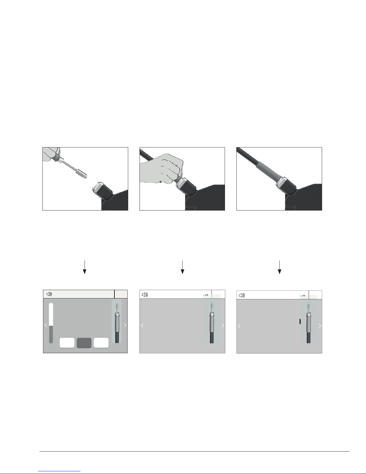
Page 9

Loosen the screw. Place the Soldering Iron in
the extractor and remove the cartridge.
Insert the cartridge and press slightly to the
mar k*.
9
Stand
Once the cartridge is properly inserted we recommend tightening the screw to prevent it turning.
Important: It is essential to insert the cartridges as far as the mark for a proper connection.
3. Fixing
*Mark
1. Removing 2. Inserting
Screw
Changing Cartridges
www.jbctools.com
Page 10
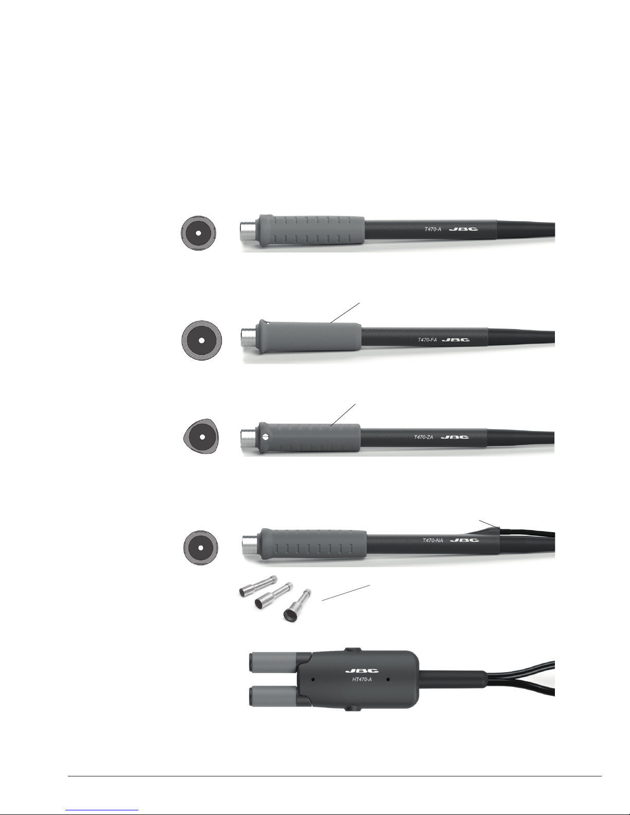
10
T470 Handles for Heavy Duty
For intensive soldering jobs requiring continued high thermal power. They feature a non-slip-grip
with a good thermal insulation and a screw which fixes the cartridge and prevents rotation.
Standard HD Iron with anti-slip grip
Ref. T470-A 1,5m (4.9ft) cable
Ref. T470-SA 3m (9.8ft) cable
Compatible Tools
Thermal Insulator HD Iron with soft grip
Ref. T470-FA 1,5m (4.9ft) cable
Ref. T470-MC 3m (9.8ft) cable
Foam
Tri-lobed HD Iron with anti-slip grip
Ref. T470-ZA 1,5m (4.9ft) cable
For better handling of the tool
Nitrogen HD Iron with anti-slip grip
Ref. T470-NA 1,5m (4.9ft) cable
Nozzles
Ref. B6193
B6194
B6195
The MNE Nitrogen
Flow Regulator
is required.
Only used with a
DN-SE stand.
Nitrogen feed
HD Thermal Tweezers
Ref. HT470-A
Only used with two
HDE-D control units
and a HDT-SD stand.
Use C470 Cartridge range.
Find the model that best suits your soldering needs in www.jbctools.com
Page 11

11
Tip Cleaner
Improve thermal transfer by cleaning the tip after each solder joint.
Brass wool
Ref. CL6210
Splashguard
Ref. 0017576
Non-slip base
Sponge
Ref. S0354
ESD Tip Wiper
Ref. CL0240
Very effective cleaning
method. It leaves a small
layer of solder on the tip to
prevent oxidation between
cleaning and rewetting.
It prevents splashing of
solder particles when
using the brass wool. No need to hold the
base while cleaning tips.
The least harmful
cleaning method. Keep
the sponge damp with
distilled water when
working to avoid tip wear.
A temperature resistant
receptacle lets the
operator remove
excess solder by gentle
tapping or wiping.
Antisplash
Membrane
Ref. 00175 74
Prevents splashing
to maintain the
work area clean.
Tapping: Wiping:
Tap to remove excess solder. Use the slots to remove remaining particles.
www.jbctools.com
Page 12

1. Pull off the fuse holder and remove the
fuse. If necessary use a tool to lever it off.
2. Press the new fuse into the fuse holder
and replace it in the station.
Fuse holder
Fuse holder
Fuse
12
Clean periodically
Before carrying out maintenance, always allow the equipment to cool.
- Clean the station screen with a glass cleaner
or a damp cloth.
- Use a damp cloth to clean the casing and
the tool. Alcohol can only be used to clean
the metal parts.
- Periodically check that the metal parts of the
tool and stand are clean so that the station
can detect the tool status.
- Maintain tip surface clean and tinned prior to
storage in order to avoid tip oxidation.
Rusty and dirty surfaces reduce heat
transfer to the solder joint.
- Periodically check all cables and tubes.
Maintenance
- Replace a blown fuse as follows:
- Replace any defective or damaged pieces. Use original JBC spare parts only.
- Repairs should only be performed by a JBC authorized technical service.
Page 13

13
It is imperative to follow safety guidelines to prevent electric shock, injury,
fire or explosion.
- Do not use the units for any purpose other than soldering or rework. Incorrect use may cause fire.
- The power cord must be plugged into approved bases. Be sure that it is properly grounded
before use. When unplugging it, hold the plug, not the wire.
- Do not work on electrically live parts.
- The tool should be placed in the stand when not in use in order to activate the sleep mode.
The soldering tip, the metal part of the tool and the stand may still be hot even when the station
is turned off. Handle with care, including when adjusting the stand position.
- Do not leave the appliance unattended when it is on.
- Do not cover the ventilation grills. Heat can cause inflamable products to ignite.
- Avoid the contact of flux with skin or eyes to prevent irritation.
- Be careful with the fumes produced when soldering.
- Keep your workplace clean and tidy. Wear appropriate protection glasses and gloves when
working to avoid personal harm.
- Utmost care must be taken with liquid tin waste which can cause burns.
- This appliance can be used by children over the age of eight and also persons with reduced
physical, sensory or mental capabilities or lack of experience provided that they have been given
adequate supervision or instruction concerning use of the appliance and understand the hazards
involved. Children must not play with the appliance.
- Maintenance must not be carried out by children unless supervised.
Safety
www.jbctools.com
Page 14

产品中有害物质的名称及含量
有害物质含量表
部件名称
有害物质
铅(Pb) 汞(Hg) 镉(Cd)
六价铬
(Cr(VI))
多溴联苯
(PBB)
多溴二苯醚
(PBDE)
烙铁头 O O O O O O
手柄 O O O O O O
电源线 O O O O O O
主机 O O O O O O
电源插座 O O O O O O
保险丝 O O O O O O
主开关 O O O O O O
电位连接 X O O O O O
变压器 O O O O O O
线路板 X O O O O O
O 表示该有害物质在该部件所有均质材料中的含量均在GB/T 26572 规定的限量要求以下。
X 表示该有害物质至少在该部件的某一均质材料中的含量超出GB/T 26572 规定的限量要求。
14
Page 15

15
Specifications
HDE-1D 120V 50/60Hz. Input fuse: 4A. Output: 42V.
HDE-2D 230V 50/60Hz. Input fuse: 2A. Output: 42V.
HDE-9D 100V 50/60Hz. Input fuse: 4A. Output: 42V.
- Temperature Range: 90 - 500 °C (190 - 932 °F) (±5%)
- Idle Temp. Stability (still air): ±1.5 ºC / ±3 ºF
- Output Peak Power: 250W
- Tip to ground resistance: < 2 ohms
- Tip to ground voltage: < 2mV RMS
- Ambient operating temp: 10 - 50 ºC (50 - 122 ºF)
- Connections: USB-A / USB-B / Peripherals connectors
RJ12 connector for Robot
- Control Unit Weight: 4,9 kg (10.8 lb)
- Control Unit Dimensions: 148 x 232 x 120 mm (5.8 x 9.1 x 4.7 in)
- Total Package: 368 x 368x 195 mm / 6.23 kg
14.5 x 14.5 x 7.7 in / 13.73 lb
Complies with CE standards.
ESD protected housing.
www.jbctools.com
Page 16

This product should not be thrown in the garbage.
In accordance with the European directive 2002/96/EC, electronic equipment at the end of its life must
be collected and returned to an authorized recycling facility.
Warranty
JBC’s two-year warranty covers this equipment
against all manufacturing defects, including the
replacement of defective parts and labour.
Warranty does not cover product wear or misuse.
In case of any manufacturing defect, the equipment
must be returned, postage paid, to the dealer where
it was purchased. Please, register your product
within 30 days of purchase in www.jbctools.com/
productregistration.
0020641-0319
www.jbctools.com
 Loading...