

Page 1
Heavy Duty Control Unit
Ref. HDE-UB
English 2
Page
Español 12
Deutsch 22
中文 32
www.jbctools.com
Page 2
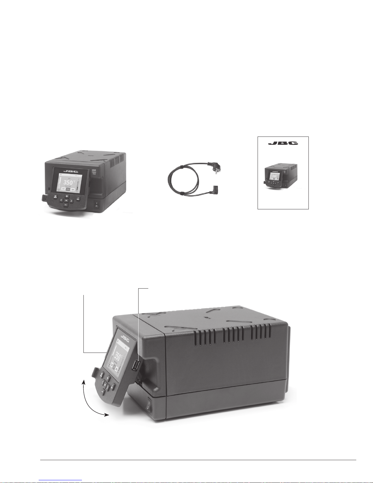
Manual ........................... 1 unit
Ref. 0016217
Features
The following items should be included:
HDE
Control Unit ................... 1 unit
Ref. HDE-1UB (120V)
HDE-2UB (230V)
HDE-9UB (100V)
Heavy Duty Control Unit
Ref. HDE-UB
Power Cord ................... 1 unit
Ref. 0010569 (230V)
0013671 (100/120V)
USB-A connector
Tilt the display
for easy reading
2.8” Color TFT screen
Packing List
2
www .jbc tool s.c om
Page 3

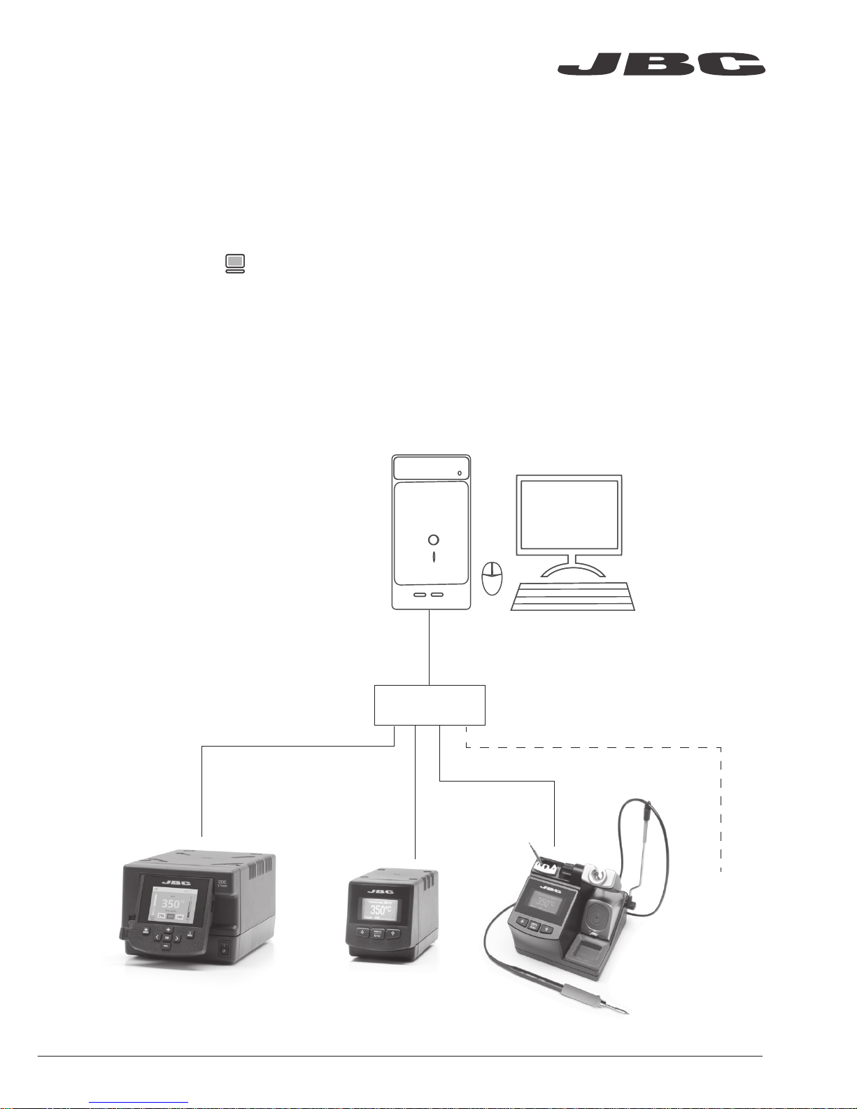
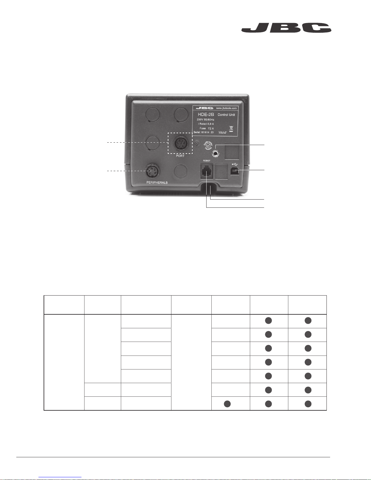
Connections
Peripherals
Stand
HDE Control Unit
RJ12 connector
for Robot system
USB-B
connector
Equipotential
connection
Power Socket
Compatibility
Select the equipment that best suit your soldering or desoldering needs.
Control
Unit
Stand Tool
Cartridge
Range
MNE-A FSE-A P-005
HDE-B
HD-SD
T470-A
C470
T470-SA
T470-ZA
T470-FA
T470-NA
HDT-SD HT470-A*
DN-SE T470-NA**
* It works with two HDE Heavy Duty stations in order to manage the cartridges individually
** The MNE Nitrogen Flow Regulator is required.
www.jbctools.com
3
Page 4

350
ºC
Port
2
Power
45%
17:14
Selected 350ºC
Port
2
17:14
Sleep
Tool in the stand
Actual Temp. 180ºC
Delay to hibernation: 29:30
Port
2
17:14
Hibernation
Actual Temp. 25ºC
T470T470
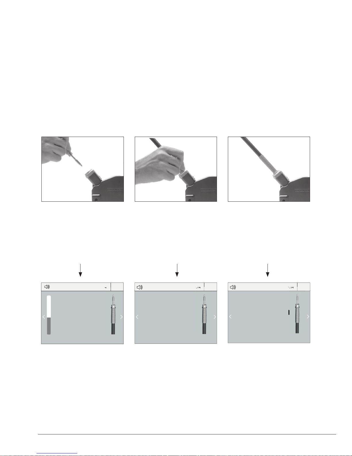
3. Hibernation
Operation
The JBC Exclusive Heating System
Our revolutionary technology is able to recover tip temperature extremely quickly. It means the user
can work at a lower temperature and improve the quality of soldering. The tip temperature is further
reduced thanks to the Sleep and Hibernation modes which increase the tip life by 5.
1. Work 2. Sleep
When the tool is lifted from the
stand the tip will heat up to the
selected temperature.
When the tool is in the stand,
the temperature falls to the
preset sleep temperature.
After longer periods of
inactivity, the power is cut off
and the tool cools down to
room temperature.
Tools Menu:
· Set temperature limits
· Select temperature levels
Tools Menu:
· Set Sleep temperature
· Set Sleep delay
(from 0 to 9 min or no Sleep)
Tools Menu:
· Set Hibernation delay
(from 0 to 60 min or no
hibernation)
Long time in
the stand
4
Page 5
380
ºC
Port
1
Power
45%
Temp. Levels
T470
250 380 400
17:14
USB flash drive is connected.
Station is controlled by a PC.
Station is controlled by a robot.
Station software update.
Press INFO to start the process.
Warning.
Press INFO for failure description.
Error. Press INFO for failure description,
the type of error and how to proceed.
System notifications (Status Bar)Menu Options
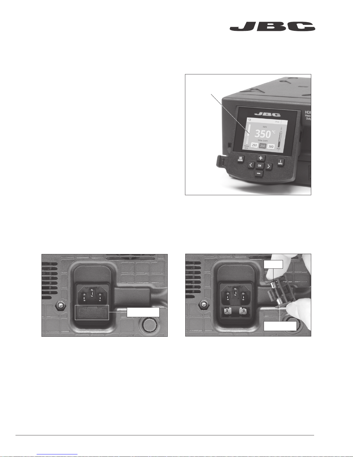
Station
Information
Power
indicator
Tool
in use
Work Screen
Status bar
The HDE offers an intuitive user interface which provides quick access to station parameters.
Change
port
Displayed if
temperature
levels are
activated
Station Tools Counters
Reset
GraphicsPeripherals
Press INFO for each parameter description.
www.jbctools.com
5
Page 6
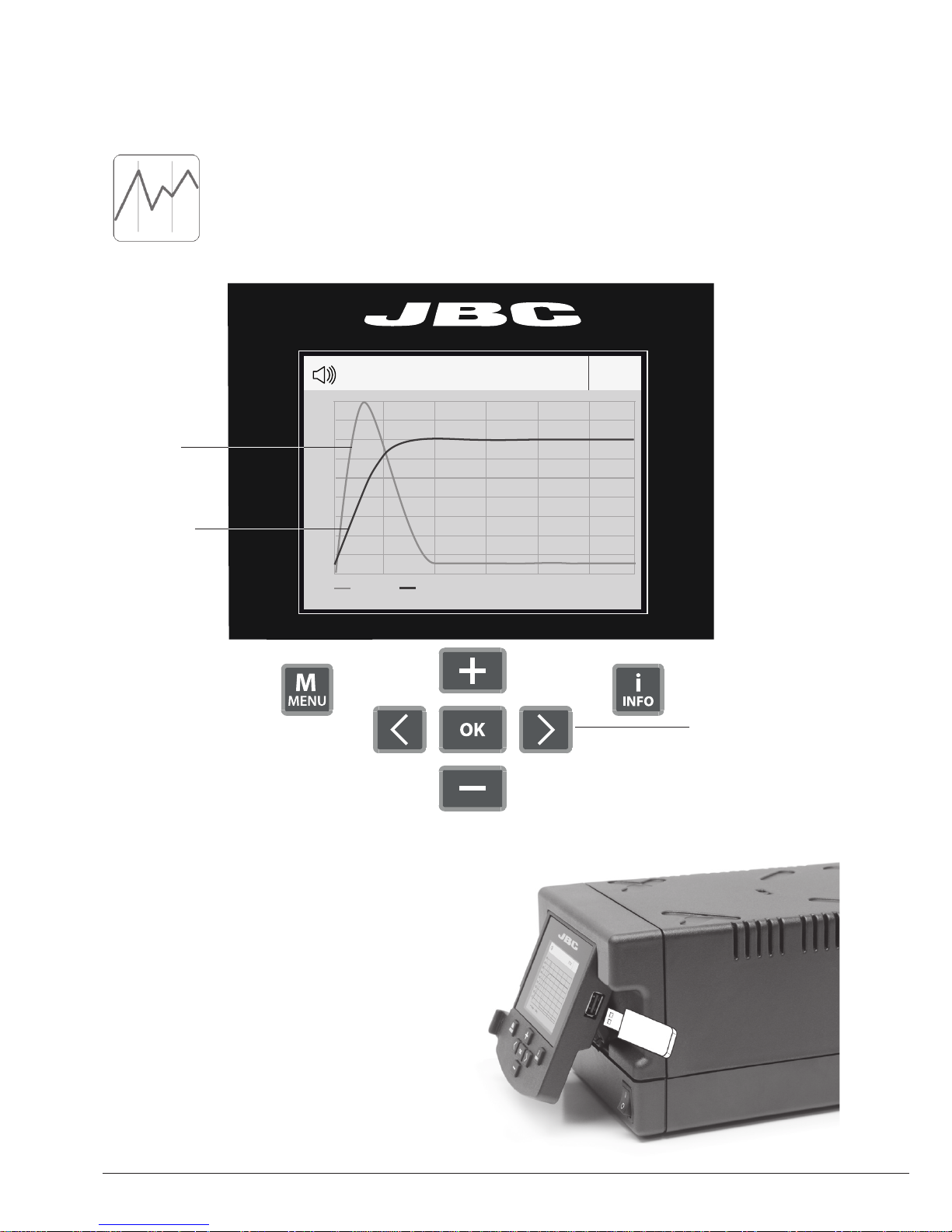
Port 1 - T470
450
400
350
300
250
150
100
50
200
Power Temp
17:14
By pressing Graphics in the main MENU, temperature and power figures in real time
are displayed for each port. This helps you decide which tip to use to obtain the best
quality solder joints.
Process analysis
Export graphics
Insert a USB flash drive into the USB-A
connector to save your soldering process in
csv format.
Graphics
Temperature
Power (%)
See other
port graphic
6
Page 7
Soldering Net
Remotely manage and monitor as many stations as your Windows PC can handle.
Functions:
- Set all the station parameters from your PC.
- Organize groups of stations and set all their parameters at the same time.
- Store specific configurations for later uses.
- Analyze the soldering graphics of the stations on your PC and export them.
1. Download the JBC Manager software and the user manual from www.jbctools.com/manager.html
2. Connect the stations via USB-B connector and the PC will automatically detect them.
3. The notification will be displayed on the station.
JBC
Manager
software
any JBC
station
USB Hub
www.jbctools.com
7
Page 8
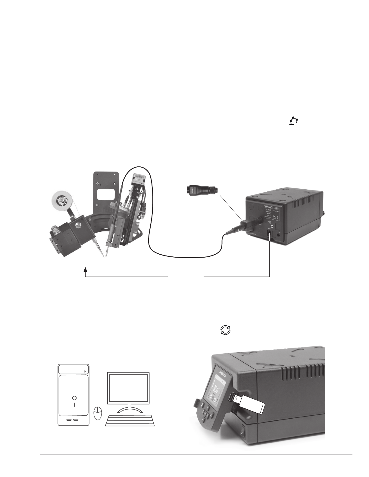
1. Connect the tool to the station port by means of the CHB-A converter.
2. Connect your Robot system to the Robot connector (RJ12) of the station.
DB9-RJ12 Adapater available only if necessary (Ref. 0013772).
3. Enable the Robot option in the station settings and the notification will be displayed:
4. Set your Robot’s commands according to the Robot Communication Protocol, available on the
website www.jbctools.com/jbcsoftware-menu-115.html
Manage and monitor the station using a Robotic system.
Working with Robots
HDE
Control Unit
Robot
Update the station software
1. Download the JBC Update file from
www.jbctools.com/software.html and save
it on a USB flash drive. Preferably one with no
other files.
JBC
Update file
Converter
Ref. CHB-A
2. Insert the USB flash drive.
The icon is diplayed while updating.
RS-232
connection
8
Page 9
Maintenance
Before carrying out maintenance or storage, always allow the equipment to cool.
1. Pull off the fuse holder and remove the fuse.
If necessary use a tool to lever it off.
2. Press the new fuse into the fuse holder and
return to the station.
Fuse holder
Fuse holder
Fuse
- Clean the station screen with a glass cleaner
or a damp cloth.
- Maintain tip surface clean and tinned prior to
storage in order to avoid tip oxidation. Rusty
and dirty surfaces reduce heat transfer to the
solder joint.
- Periodically check all cables and tubes.
- Replace a blown fuse as follows:
Clean
periodically
- Replace any defective or damaged pieces. Use original JBC spare parts only.
- Repairs should only be performed by a JBC authorized technical service.
www.jbctools.com
9
Page 10

It is imperative to follow safety guidelines to prevent electric
shock, injury, fire or explosion.
- Do not use the units for any purpose other than soldering or rework. Incorrect use may cause fire.
- The power cable must be plugged into approved bases. Make sure that it is properly grounded
before use. When unplugging it, hold the plug, not the wire.
- Do not work on electrically live parts.
- The tool should be placed in the stand when not in use in order to activate the sleep mode.
The soldering tip, the metal part of the tool and the stand may still be hot after the station
is turned off. Handle with care, including when adjusting the stand position.
- Do not leave the appliance unattended when it is on.
- Do not cover the ventilation grills. Heat can cause inflamable products to ignite.
- Avoid flux coming into contact with skin or eyes to prevent irritation
- Be careful with the fumes produced when soldering.
- Keep your workplace clean and tidy. Wear appropriate protection glasses and gloves when
working to avoid personal harm.
- Utmost care must be taken with liquid tin waste which can cause burns.
- This appliance can be used by children over the age of eight as well as persons with reduced
physical, sensory or mental capabilities or lacking experience provided that they have been given
adequate supervision or instruction concerning use of the appliance and understand the hazards
involved. Children must not play with the appliance.
- Maintenance must not be carried out by children unless supervised.
Safety
10
Page 11

Specifications
HDE-1UB 120V 50/60Hz. Input fuse: 4A. Output: 47V.
HDE-2UB 230V 50/60Hz. Input fuse: 2A. Output: 47V.
HDE-9UB 100V 50/60Hz. Input fuse: 4A. Output: 47V.
- Weight: 4.3 Kg (9.5 lb)
- Dimensions: 145 x 120 x 225 mm
- Output Peak Power: 250W
- Temperature Range: 90 - 500 °C / 190 - 932 °F (±5%)
- Idle Temp. Stability (still air): ±1.5 ºC / ±3 ºF
- Tip to ground resistance: <2 ohms
- Tip to ground voltage: <2mV RMS
- Ambient operating temp: 10 - 40 ºC / 50 - 104 ºF
- Connections USB-A / USB-B / Peripherals connectors
RJ12 connector for Robot
Complies with CE standards
ESD protected housing “skin effect”
www.jbctools.com
11
Page 12
Conector USB-A
Incline la
pantalla para
una mejor lectura
Pantalla color TFT de 2,8”
Manual ........................... 1 unit
Ref. 0016217
Los siguientes artículos deben estar incluidos:
HDE Control Unit
HDE Unidad
de Control ................... 1 unidad
Ref. HDE-1UB (120V)
HDE-2UB (230V)
HDE-9UB (100V)
Power Cord
Cable de red .................... 1 ud.
Ref. 0010569 (230V)
0013671 (100/120V)
Composición
Heavy Duty Control Unit
Ref. HDE-UB
Características
12
www .jbc tool s.c om
Page 13
Conector RJ12 para sistemas
de robot
Periféricos
Sopor te
Toma de red
Conexiones
Unidad de Control HDE
Compatibilidades
Seleccione los equipos que más se adapten a sus necesidades de soldadura.
Unidad de
Control
Soporte Herramientas
Gama de
cartuchos
MNE-A FSE-A P-005
HDE-B
HD-SD
T470-A
C470
T470-SA
T470-ZA
T470-FA
T470-NA
HDT-SD HT470-A*
DN-SE T470-NA**
* Necesita 2 Unidades HDE para poder controlar cada cartucho individualmente.
** Se requiere el Regulador de Flujo de Nitrógeno MNE.
Conector USB-B
Conexión
equipotencial
www.jbctools.com
13
Page 14
380
ºC
Port
1
Power
45%
Selected 380ºC
T470
17:14
Sleep
Port
1
Tool in the stand
17:14
Actual Temp. 180ºC
T470
Delay to hibernation: 29:30
Port
1
Actual Temp. 25ºC
17:14
T470
Hibernation
3. Hibernación
Funcionamiento
El Exclusivo Sistema Calefactor de JBC
Nuestra tecnología revolucionaria es capaz de recuperar la temperatura de la punta de forma
extremadamente rápida. Esto significa que el usuario puede trabajar a una temperatura más baja
y mejorar la calidad de la soldadura. Esta temperatura se reduce aún más gracias a los modos de
Sleep e Hibernation que incrementan hasta 5 veces la vida de las puntas.
1. Trabajo 2. Sleep
Al levantar la herramienta
del soporte, la punta se
calienta hasta la temperatura
seleccionada.
Cuando la herramienta está
en el soporte, la temperatura
se reduce a la temperatura de
Sleep predefinida.
Tras largos períodos de
inactividad, se corta el
suministro de energía y
la punta se enfría hasta
temperatura ambiente.
Menú Tools:
· Configure límites de
temperatura.
· Seleccione niveles de
temperatura.
Menú Tools:
· Configure la temperatura
de Sleep
· Configure el tiempo de
retraso de Sleep
(de 0 a 9 min o ninguno)
Menú Tools:
· Configure el retraso de
Hibernación
(de 0 a 60 min o ninguno)
Largos
períodos en
el soporte
14
Page 15

380
ºC
Port
1
Power
45%
Temp. Levels
T470
250 380 400
17:14
Unidad de memoria USB conectada.
Estación controlada por un PC.
Estación controlada por un robot.
Actualización del software de la estación.
Pulse INFO para iniciar el proceso.
Aviso.
Pulse INFO para la descripción del fallo.
Error. Pulse INFO para la descripción del
fallo, el tipo de error y cómo proceder.
Notificaciones (Barra de estado)
Ayuda de la
estación
Indicador de
potencia
Herramienta
en uso
Pantalla de trabajo
Barra de
estado
La HDE-B presenta una interfaz de usuario intuitiva y ofrece un rápido acceso a los parámetros.
Cambio de
puerto
Se muestra si
los niveles de
temperatura
están activos
Pulse INFO para la descripción de parámetros.
Opciones de Menú
Station Tools
Counters
Reset
GraphicsPeripherals
www.jbctools.com
15
Page 16

Port 1 - T245
450
400
350
300
250
150
100
50
200
Power Temp
17:14
Pulsando sobre Graphics en el menú principal, se muestran las respuestas de
temperatura y potencia en tiempo real de cada puerto. Esto le ayudará a decidir cuál
es la punta más adecuada para obtener la mejor calidad en sus soldaduras.
Análisis del proceso
Exporte gráficos
Inserte una unidad de memoria USB para
guardar su proceso de trabajo en formato csv.
Temperatura
Potencia (%)
Vea el gráfico
del otro puerto
Graphics
16
Page 17

Red de soldadura
Gestione y monitorice tantas estaciones como soporte su PC.
Funciones:
- Configure todos los parámetros de la estación desde su PC.
- Organice grupos de estaciones y configure todos sus parámetros al mismo tiempo.
- Guarde configuraciones específicas para usos posteriores.
- Analice gráficos del proceso de soldadura de las estaciones desde su PC y expórtelos.
cualquier
estación
JBC
JBC
Manager
software
USB Hub
1. Descargue el software JBC Manager y el manual de usuario de www.jbctools.com/manager.html
2. Conecte las estaciones a través del conector USB-B y el PC las detectará automáticamente.
3. La notificación se mostrará en la estación.
www.jbctools.com
17
Page 18

Gestione y monitorice la estación por medio de un sistema robotizado.
1. Conecte la herramienta a la estación utilizando el convertidor CHB-A.
2. Conecte su sistema robotizado al conector Robot de la estación (RJ12).
Si lo necesita, el adaptador DB9-RJ12 puede encontrarlo con la referencia Ref. 0013772.
3. Active la opción de robot en la estación y se mostrará la siguiente notificación:
4. Configure su sistema robotizado según el Protocolo de Comunicación para Robots,
que encontrará en www.jbctools.com/jbcsoftware-menu-115.html.
Trabajar con Robots
Robot
Actualice el software de la estación
1. Descargue el archivo de actualización de
www.jbctools. com/software.html
cuando esté disponible y guárdelo en una
unidad de memoria USB (preferentemente
una sin otros archivos).
JBC
Update File
Convertidor
Ref. CHB-A
Conexión
RS-232
2. Inserte la unidad de memoria USB.
La notificación se muestra mientras
se actualiza el software.
HDE
Unidad de
Control
18
Page 19

Mantenimiento
Antes de realizar tareas de mantenimiento o almacenar, desconecte el equipo y déjelo enfriar.
1. Tire del portafusible para retirar el fusible.
Si lo precisa, utilice una pequeña palanca.
2. Sustituya el fusible y coloque de nuevo el
portafusibles en su sitio.
- Use un paño húmedo para limpiar la
pantalla del equipo, la carcasa y la
herramienta. Puede utilizar alcohol
solamente en las partes metálicas.
- Mantenga la punta limpia y estañada la
para evitar su oxidación. Las superfícies
sucias reducen la transferencia térmica a la
soldadura.
- Revise periódicamente los tubos y cables.
- Cambie el fusible fundido de la siguiente
manera:
Portafusible
Portafusible
Fusible
- Cambie cualquier pieza defectuosa o dañada. Utilice solamente recambios originales de JBC.
- Cualquier reparación sólo se podrá realizar por un servicio técnico oficial JBC.
Limpie
periódicamente
www.jbctools.com
19
Page 20

Es necesario cumplir estas normas de seguridad para prevenir cualquier
choque eléctrico, heridas, fuego o explosiones.
Seguridad
- No utilice el equipo para otros fines que no sea la soldadura o reparación. El uso incorrecto
puede causar fuego.
- El cable de red debe enchufarse en bases homologadas. Asegúrese de que está conectado a
tierra correctamente antes de su uso. Al retirarlo, tire del conector, no del cable.
- No trabaje con tensión.
- La herramienta debe permanecer en el soporte mientras no está en uso con el fin de activar el modo
de Sleep o Hibernación. El cartucho y las partes metálicas de la herramienta o del soporte pueden
estar calientes incluso cuando con la estación apagada. Manipule con cuidado, incluso cuando se
ajusta la posición del soporte.
- No deje el aparato desatendido cuando está en funcionamiento.
- No cubra las rejillas de ventilación. El calor puede causar que los productos inflamables se enciendan.
- Evite el contacto del Flux con la piel o los ojos para prevenir la irritación.
- Tenga cuidado con el humo producido al trabajar.
- Mantenga su lugar de trabajo limpio y ordenado. Use gafas y guantes de protección adecuados
Así evitará cualquier daño.
- Tenga cuidado con los restos de estaño líquido. En contacto con la piel, puede causar quemaduras.
- Este aparato puede ser utilizado por personas a partir de 8 años y también por aquellas
personas con movilidad reducida o capacidades físicas, sensoriales o mentales limitadas o
con falta de experiencia y conocimientos siempre y cuando reciban supervisión o instrucciones
relativas al uso del aparato de una manera segura y entiendan los riesgos que implica. Los niños
no deben jugar con el aparato.
- Los niños no deberán realizar tareas de mantenimiento sin supervisión.
20
Page 21

Especificaciones
HDE-1UB 120V 50/60Hz. Input fuse: 4A. Output: 47V.
HDE-2UB 230V 50/60Hz. Input fuse: 2A. Output: 47V.
HDE-9UB 100V 50/60Hz. Input fuse: 4A. Output: 47V.
- Peso: 4.3 Kg (9.5 lb)
- Dimensiones: 145 x 120 x 225 mm
- Potencia máxima: 250W
- Rango de temperatura: 90 - 500 °C / 190 - 932 °F (±5%)
- Estabilidad de temp. en reposo: ±1.5 ºC / ±3 ºF
- Resistencia punta a tierra: <2 ohms
- Tensión en punta: <2mV RMS
- Temp. ambiente de trabajo: 10 - 40 ºC / 50 - 104 ºF
- Conexiones USB-A / USB-B / Periféricos
Connector para Robot RJ12
Cumple con las normativas CE
Seguridad ESD
www.jbctools.com
21
Page 22

USB-A-Anschluss
Das Display zum
einfachen Ablesen
kippen
2,8” Farb TF T Bildschirm
Handbuch ................... 1 Stück
Ref. 0016217
HDE Control Unit
HDE Steuereinheit ...... 1 Stück
Ref. HDE-1UB (120V)
HDE-2UB (230V)
HDE-9UB (100V)
Power Cord
Netzkabel...................... 1 Stück
Ref. 0010569 (230V)
0013671 (100/120V)
Merkamle
Die folgenden Artikel sollten enthalten sein:
Packliste
Heavy Duty Control Unit
Ref. HDE-UB
22
www .jbc tool s.c om
Page 23

RJ12-Anschluss
für Robotersystem
Peripheriegerät
Stand
Netzsteckdose
Anschluss
HDE Steuereinheit
Kompatibilität
Wählen Sie die Ausrüstung nach Ihren Lötbedürfnisse aus.
Steuereinheit Ständer Werkzeug Kartuschen MNE-A FSE-A P-005
HDE-B
HD-SD
T470-A
C470
T470-SA
T470-ZA
T470-FA
T470-NA
HDT-SD HT470-A*
DN-SE T470-NA**
* Sie benötigen 2 Löteinheiten HDE um die Lötkartuschen der HT470-A einzeln zu steuern.
** Für den T470-NA wird der Durchflussregler für Stickstoff MNE erforderlich.
USB-B-Anschluss
Potenzialausgleichsbuchse
www.jbctools.com
23
Page 24

380
ºC
Port
1
Power
45%
Selected 380ºC
T470
17:14
Sleep
Port
1
Tool in the stand
17:14
Actual Temp. 180ºC
T470
Delay to hibernation: 29:30
Port
1
Actual Temp. 25ºC
17:14
T470
Hibernation
3. Überwinterung
Betrieb
Das exklusive Heizsystem von JBC
Diese revolutionäre Technik ist dazu in der Lage, außerordentlich schnell die Spitzentemperatur zu
erreichen. Dies ermöglicht es dem Benutzer, mit einer niedrigeren Temperatur zu arbeiten.
Daraus ergibt sich eine fünfmal längere Spitzenstandzeit.
1. Arbeit 2. Sleep
Nehmen Sie das Werkzeug
aus der Ablage und die
Werkzeugspitze wird auf
die gewählte Temperatur
aufgeheizt.
Wenn sich das Werkzeug
in der Ablage befindet,
wird die Temperatur auf
voreingestellte SleepTemperatur abgesenkt.
Nach längeren Zeiträumen
der Untätigkeit wird
die Stromversorgung
abgeschaltet und das
Werkzeug kühlt auf
Raumtemperatur ab.
Menü Tools:
· Ruhetemperatur einstellen
· Ruheverzögerung einstellen
(von 0 bis 9 Min. oder kein
Ruhezustand)
Menü Tools:
· Standbyverzögerung eins
tellen
(von 0 bis 60 Min. oder kein
Standby)
Lange
Zeit in die
Ablage
Menü Tools:
· Temperaturgrenzwerte
einstellen
· Temperaturstufen
auswählen
24
Page 25

380
ºC
Port
1
Power
45%
Temp. Levels
T470
250 380 400
17:14
Station Werkzeuge
Zähler
Reset
GraphicsPeripheriegeräte
USB-Flashspeicher ist angeschlossen.
Station wird von einem PC gesteuert.
Station wird von einem Roboter gesteuert.
Aktualisierung Stationssoftware.
Drücken Sie INFO, um den Prozess zu starten.
Warnung.
Drücken Sie INFO zur Störungsbeschreibung.
Fehler. Drücken Sie INFO zur Störungsbeschreibung, des Fehlertyps und empfohlenen
Vorgehensweise.
Systemmeldungen (Statusleiste)
Station
Information
Leistungsanzeige
Benutztes
Werkzeug
Arbeitsbildschirm
Statusleiste
Das HDE-B bietet eine intuitive Benutzerschnittstelle, die schnellen Zugriff auf die Stationsparameter
gewährt.
Port
wechseln
Angezeigt,
wenn
Temperaturstufen aktiviert
sind
Drücken Sie INFO für jede ParameterBeschreibung.
Menüoptionen
www.jbctools.com
25
Page 26

Port 1 - T245
450
400
350
300
250
150
100
50
200
Power Temp
17:14
Graphics
Beim Drücken von Graphics im Haupt-MENÜ, werden für jeden Port in Echtzeit
Temperatur- und Leistungsangaben eingeblendet. Dies hilft Ihnen bei der
Entscheidung, welche Spitze Sie für die beste Qualität der Lötverbindungen
benutzen müssen.
Prozessanalyse
Grafiken exportieren
Stecken Sie einen USB Flashspeicher in den
USB-A-Anschluss, um mit dem Speichern
Ihres Lötprozesses im csv-Format zu
beginnen.
Temperatur
Leistung (%)
Siehe andere
Portgrafik
26
Page 27

JBC
Manager
software
irgendeine
JBC
Station
USB Hub
Lötnetz
So viele Stationen, wie Ihr Windows-PC bewältigen kann, aus der Ferne steuern und überwachen.
1. Laden Sie die JBC Manager Software und das Benutzerhandbuch herunter unter
www.jbctools.com/manager.html
2. Schließen Sie die Stationen per USB-B-Anschluss an und der PC wird sie automatisch erkennen.
3. Die Meldung wird auf der Station angezeigt werden.
Funktionen:
- Alle Stationsparameter von Ihrem PC aus einstellen.
- Stationsgruppen organisieren und alle ihre Parameter zur selben Zeit einstellen.
- Spezifische Konfigurationen für spätere Anwendungen speichern.
- Die Lötgrafiken der Stationen auf Ihrem PC analysieren und sie exportieren.
www.jbctools.com
27
Page 28

1. Schließen Sie das Werkzeug mit einem CHB-A Konverter an den Stationsport an.
2. Verbinden Sie Ihr Robotersystem mit der Roboterbuchse (RJ12) der Station.
Sollten Sie bei Bedarf den DB9-RJ12 Stecker benötigen, dieser ist verfügbar unter (Ref. 0013772).
3. Aktivieren Sie die Roboteroption in den Stationseinstellungen und die Mitteilung wird angezeigt
werden:
4. Gestalten Sie Ihre Roboter-Befehle gemäß dem Roboter-Kommunikations-Protokoll, verfügbar
auf der Website www.jbctools.com/jbcsoftware-menu-115.html.
Verwalten und Monitorüberwachung der Lötstation durch ein Robotersystem.
Arbeit mit Robotern
Roboter
RS-232-buchse
HDE
Steuereinheit
JBC
Updatedatei
Stationssoftware aktualisieren
1. Laden Sie die JBC Updatedatei herunter
unter www.jbctools.com/software.html
und speichern Sie sie auf einem USB-
Flashspeicher. Möglichst einer ohne
andere Dateien.
Konverter
Ref. CHB-A
2. Stecken Sie den USB-Flashspeicher ein.
Das Symbol wird während des
Aktualisierens angezeigt.
28
Page 29

Wartung
Vor der Durchführung von Wartungsarbeiten oder Einlagerung die Geräte immer erst auskühlen
lassen.
- Benutzen Sie einen feuchten Lappen, um
das Gehäuse und das Werkzeug zu reinigen.
Alkohol darf nur zur Reinigung der Metallteile
benutzt werden.
- Halten Sie die Oberfläche der Spitze vor
der Aufbewahrung sauber und verzinnt, um
Spitzenoxidation zu vermeiden. Rostige und
verschmutzte Oberflächen mindern den
Wärmedurchgang zur Lötstelle.
- Überprüfen Sie regelmäßig alle Kabel und
Schläuche.
- Jedes defekte oder schadhafte Teil austauschen. Nur Original-Ersatzteile von JBC verwenden.
- Reparaturen dürfen nur von dem Vertragskundendienst von JBC durchgeführt werden.
Regelmäßig reinigen
1. Ziehen Sie die Sicherungshalterung
heraus und entnehmen Sie die Sicherung.
Benutzen Sie bei Bedarf ein Werkzeug,
um sie herauszudrücken.
2. Drücken Sie die neue Sicherung in die
Halterung und setzen Sie sie erneut in die
Station ein.
- Eine durchgebrannte Sicherung wie folgt austauschen:
Sicherung-
shalterung
Sicherung-
shalterung
Sicherung
www.jbctools.com
29
Page 30

Die Sicherheits-Leitlinien müssen unbedingt eingehalten werden, um
elektrischen Schlag, Verletzung, Feuer oder Explosion zu vermeiden.
Sicherheit
- Die Anlagen für keinen anderen Zweck verwenden als zum Löten oder Entlöten. Unsachgemäße
Verwendung kann Feuer hervorrufen.
- Das Netzkabel muss in zugelassene Steckdosen eingesteckt werden. Vergewissern Sie sich vor
der Benutzung, dass sie korrekt geerdet ist. Beim Herausziehen am Stecker ziehen, nicht am
Kabel.
- Nicht an aktiven Bauteilen arbeiten.
- Das Werkzeug sollte bei Nichtgebrauch in der Ablage abgestellt werden, um die Betriebsart Sleep
auszulösen.
Die Lötspitze, der metallische Teil des Werkzeugs und die Ablage können noch heiß sein, wenn die
Station ausgeschaltet ist. Gehen Sie vorsichtig vor, sogar wenn Sie die Ständerposition justieren.
- Das eingeschaltete Gerät niemals unbeaufsichtigt lassen.
- Die Kühlungsgitter nicht abdecken. Hitze kann entzündliche Stoffe entzünden.
Ein als "ohne Rückstände" eingestuftes Flussmittel verwenden und die Berührung mit Haut oder
Augen vermeiden, um Reizung vorzubeugen.
- Sich vor dem beim Löten entstehenden Rauch in Acht nehmen.
- Ihren Arbeitsplatz sauber und aufgeräumt halten. Bei der Arbeit geeignete Schutzbrille und
Handschuhe tragen, um gesundheitliche Schäden zu vermeiden.
- Im Umgang mit flüssigen Zinnrückständen muss äußerste Sorgfalt walten.
- Dieses Gerät kann von Kindern über acht Jahren und auch Personen mit körperlicher, sinnlicher
oder geistiger Behinderung oder mangelnder Erfahrung benutzt werden, nachdem ihnen
angemessene Überwachung oder Einweisung hinsichtlich der Verwendung des Geräts und der
damit verbundenen Risiken gegeben worden ist. Kinder dürfen mit dem Gerät nicht spielen.
- Wartung darf nicht von Kindern durchgeführt werden, wenn sie hierbei nicht beaufsichtigt werden.
30
Page 31

HDE-1UB 120V 50/60Hz. Eingangssicherung: 4A. Output: 47V.
HDE-2UB 230V 50/60Hz. Eingangssicherung: 2A. Output: 47V.
HDE-9UB 100V 50/60Hz. Eingangssicherung: 4A. Output: 47V.
- Gewicht: 4.3 Kg (9.5 lb)
- Abmessungen: 145 x 120 x 225 mm
- Spitzenausgangsleistung: 250W
- Temperaturbereich: 90 - 500 °C / 190 - 932 °F (±5%)
- emperaturstabilität (stillstehende Luft): ±1.5 ºC / ±3 ºF
- Spitze-Erde-Widerstand: <2 ohms
- Spitze-Erde-Spannung: <2mV RMS
- Umgebungsbetriebstemperatur: 10 - 40 ºC / 50 - 104 ºF
- Anschluss USB-A / USB-B / Peripheriegeräteanschlüsse
RJ12-Buchse für Roboter
Erfüllt EG-Normen
ESD-gerechtes Gehäuse “skin effect”
Technische Daten
www.jbctools.com
31
Page 32

Heavy Duty Control Unit
Ref. HDE-UB
说明书 ............................... 1 件
Ref. 0016217
产品特性
需包含以下部件:
HDE 控制主机 .................. 1 件
Ref. HDE-1UB (120V)
HDE-2UB (230V)
HDE-9UB (100V)
电源线 ............................... 1 件
Ref. 0010569 (230V)
0013671 (100/120V)
USB-A 连接口
云台显示
方便阅读
2.8” 彩色液晶屏
产品描述
32
www .jbc tool s.c om
Page 33

机器人系统
RJ12连接口
USB-B
连接口
等电位
连接口
电源插口
连接口
外设连接口用于
连接模块盒脚
踏板
支架
HDE 控制主机
性能
根据焊接或拆焊需求选择最适合的设备
控制主机 工具座 工具 烙铁头系列
MNE-A FSE-A P-005
HDE-B
HD-SD
T470-A
C470
T470-SA
T470-ZA
T470-FA
T470-NA
HDT-SD HT470-A*
DN-SE T470-NA**
* 它可连接两个重负荷焊接工作站,并可单独管理各工作站的烙铁头。
** 需要MNE氮气流量调节器
www.jbctools.com
33
Page 34

350
ºC
Port
2
Power
45%
17:14
Selected 350ºC
Port
2
17:14
Sleep
Tool in the stand
Actual Temp. 180ºC
Delay to hibernation: 29:30
Port
2
17:14
Hibernation
Actual Temp. 25ºC
T470T470
3. 休眠 (Hibernation)
操作
JBC 专属加热系统
革命性技术,可以令烙铁头温度快速回升。
这意味着用户可以在较低温度下操作,并提高焊接质量。
之后,烙铁头温度在睡眠和休眠模式下降低,可令其寿命延长五倍。
1. 工作 2. 睡眠 (Sleep)
当工具从支架下取下时,
烙 铁 头 温 度 会加 热 到 选 定 温
度。
当工具放置在支架上时,
温度会下降到
预置睡眠温度。
长时间没有使用后,电源会切
断,工具会冷却到室温。
工具菜单:
· 设定温度极限
· 选择温度等级
工具菜单:
· 设定睡眠温度
· 设定睡眠延时
(从 0 至 9 分钟或无睡眠)
工具菜单:
· 设定休眠延时
(从 0 至 60 分钟或无休眠)
长时间放置
在支架上
34
Page 35

380
ºC
Port
1
Power
45%
Temp. Levels
T470
250 380 400
17:14
USB闪存盘已连接。
工作站由电脑控制。
工作站由机器人控制。
工作站软件更新。
按 INFO 启动更新。
警告。
按 INFO 查阅故障说明。
错误。 按 INFO 查阅故障说明,
故障类型,及如何处理。
系统通知 (状态条)菜单选项
工作站
信息
功率
指示条
使用中
的工具
工作屏
状态条
HDE 提供了一个直观的用户界面,可以快速访问工作站的参数。
更换
端口
只有在使用
温度等级时
才会显示
主机 工具 读数表
重设
图形
外设
按 INFO 查阅每个参数的说明。
www.jbctools.com
35
Page 36

Port 1 - T470
450
400
350
300
250
150
100
50
200
Power Temp
17:14
通过按下主菜单上的图形,每个端口响应的实时温度和功率被显示出来。这有助于
您决定使用哪种焊嘴来获得最佳的焊接质量。
流程分析
图形导出
插入USB 闪存盘到USB-A 连接口,开始保存
您的焊接流程,导出文档为csv格式。
图形
温度
功率 (%)
访问其他
端口图形
36
Page 37

焊接网络
由您的电脑远程管理和监控尽可能多的工作站。
功能说明:
- 从您的电脑上设定所有工作站的参数。
- 创建工作站组群并同时设定它们的参数。
- 保存特定的配置以便以后使用。
- 从您的电脑上分析焊接图形并导出。
1. 下载 JBC管理者软件和用户手册,下载页面 www.jbctools.com/manager.html
2. 工作站连接到USB-B 连接口,电脑将会自动探测到它们。
3. 通知 将在工作站上显示。
JBC
Manager
software
任何 JBC
主机
USB 集线器
www.jbctools.com
37
Page 38

1. 通过转换接头来连接工具到工作站端口。
2. 通过工作站上的(RJ12)机器人连接口,连接您的机器人系统。
DB9-RJ12 适配器仅在必要时提供 (型号 0013772).
3. 在工作站设置中启用机器人选项, 将显示通知:
4. 根据机器人通讯协议设定您的机器人指令,可以从以下页面获得
www.jbctools.com/jbcsoftware-menu-115.html.
Manage and monitor the station using a Robotic system.
Working with Robots
HDE
控制主机
机器人
升级工作站软件
1. 下载JBC升级文档,下载页面
www.jbctools.com/software.html,
并保存到USB闪存盘。 优选空白闪存盘。
JBC
升级文档
转换接头
型号
Ref. CHB-A
2. 插入USB闪存盘。
升级时显示 图标。
RS-232
连接口
38
Page 39

维护保养
在进行维护和存放之前,确认设备已冷却。
1. 拔下保险丝托架并取出保险丝。 如有必
要可使用工具撬动。
2. 按入新保险丝到托架内并放回到工作站。
保险丝托架
保险丝托架
保险丝
- 用玻璃清洁剂或湿布清洁焊台屏幕。
- 用湿布清洁机壳和工具。 酒精只能清洁金
属部分。
- 定期检查工具和主机的金属部分是否清洁,
确保焊台可以检测到工具状态。
- 保持焊嘴表面清洁并在存放前加锡保养以防
氧化。 生锈和肮脏的表面会减少到焊点的
热传递。
- 定期检查所有的电缆连接线和软管。
- 更换熔断的保险丝如下:
Clean
periodically
- 更换任何不良或受损件。 只可以使用JBC原厂配件。
- 维修只可以由JBC授权的技术服务来执行。
www.jbctools.com
39
Page 40

安全
必须遵守安全准则,以防止电击,人身伤害,火灾或爆炸。
- 请勿使用焊台于焊接或返修以外的任何目的。 不正当的使用可能引起火灾。
- 电源线必须插入核准的电源。 确保在使用前正确接地。 拔下时应握住插头而不是电源线。
- 请勿在带电零件上工作。
- 工具不使用时应放在置放架上以激活睡眠模式。
主机关闭后焊嘴, 工具和焊台的金属部分可能仍然是热的。 请小心处理, 哪怕是在调整工作站
位置时。
- 设备运行是要始终有人看管。
- 请勿覆盖通风孔。 热量可能会导致易燃品点燃。
- 使用“无残留”类助焊剂并避免与皮肤或眼睛接触, 以防刺激。
- 小心焊接时产生的烟雾。
- 保持您工作场所的干净整洁。 操作时, 为避免人身伤害, 请穿戴适当的防护眼镜和手套。
- 残锡液易引起灼伤, 请小心处理。
- 本产品允许八岁以上儿童,肢体,感官或心智有残缺的人士,以及缺乏经验的人士使用,
但必须提供必要的监护及指导,并且了解本产品可能涉及的危险。切勿让儿童把玩。
- 没有监管,儿童不得对本产品进行维护。
40
Page 41

技术规格
HDE-1UB 120V 50/60Hz. 输入保险丝: 4A. 输出: 47V.
HDE-2UB 230V 50/60Hz. 输入保险丝: 2A. 输出: 47V.
HDE-9UB 100V 50/60Hz. 输入保险丝: 4A. 输出: 47V.
- 重量: 4.3 Kg (9.5 lb)
- 尺寸: 145 x 120 x 225 mm
- 输出峰值功率: 250W
- 温度范围: 90 - 500 °C / 190 - 932 °F (±5%)
- 待机温度稳定性 (静止空气): ±1.5 ºC / ±3 ºF
- 焊接接地电阻: <2 ohms
- 焊接接地电压: <2mV RMS
- 工作环境温度: 10 - 40 ºC / 50 - 104 ºF
- Connections USB-A / USB-B / 外设连接口
RJ12 机器人连接口
符合 CE 标准
ESD 防静电“趋肤效应”保护机壳
www.jbctools.com
41
Page 42

42
Page 43

Exploded View · Despiece · Explosionszeichnung · 分解图
www.jbctools.com
43
Page 44

Warranty
JBC’s 2 year warranty covers
this equipment against all
manufacturing defects, including
the replacement of defective parts
and labour.
Warranty does not cover product
wear or misuse.
In order for the warranty to be
valid, equipment must be returned,
postage paid, to the dealer where
it was purchased.
This product should not be thrown in the garbage.
In accordance with the European directive 2012/19/EU, electronic equipment at the end of their life
must be collected and returned to an authorized recycling facility.
Garantía
Esta garantía de 2 años cubre este
equipo contra cualquier defecto
de fabricación, incluyendo la
sustitución de partes defectuosas
y mano de obra.
La garantía no cubre el desgaste
del producto por uso o mal uso.
Para que esta garantía sea válida,
el equipo debe ser devuelto, a
portes pagados, al distribuidor
donde se compró.
Este producto no debe desecharse en la basura.
De acuerdo a la directiva europea 2012/19/UE, los equipos electrónicos al final de su vida se deberán
recoger y trasladar a una planta de reciclaje autorizada.
Garantie
Die 2-Jahres-Garantie von JBC
ersteckt sich auf das Gerät bei
Herstellungsfehlern, einschließlich
Fehlern der Verarbeitung und dem
Ersatz defekter Teile und deren
Austausch.
Die Garantie gilt nicht für
Produktverschleiß durch normale
Nutzung oder durch falsche
Anwendung.
Damit die Garantie Gültigkeit
erlangt, muß das Gerät an den
Händler, bei dem es gekauft
wurde, zurückgesand weden
(Porto bezahlt).
Dieses Produkt sollte nicht mit dem Hausmüll entsorgt werden.
In Übereinstimmung mit der europäischen Richtlinie 2012/19/EU müssen elektronische Geräte am
Ende ihrer Lebensdauer eingesammelt und einem autorisierten Recyclingbetrieb zugeführt werden.
保修
JBC的2年保修涵盖了该设备所有的
制造缺陷,
包括更换有缺陷的零件和人工耗
时。
保修不包括因过度使用或误用而产
生的产品损坏。
为了使保修有效,
设备须返还至购买时的经销商处返
修,邮资自理。
本产品不应被扔在垃圾筒内。
根据欧盟条款2012/19/EU,电子设备在其寿命结束后必须被回收并转运至授权回收工厂。
www.jbctools.com
0016217-1216
 Loading...