

Page 1
HDE-A Robot station
Ref. HDRE-A
English
www.jbctools.com
Page 2
ww w.jb ct oo ls. co m
2 3
Packing List
The followin g items should be i ncluded:
HDE Contr ol Unit ..............................................1 unit
Ref. HDE-1A (120V)
HDE-2A (230V)
HDE-9A (100V)
Genera l purpose HD Ha ndle
with 3m cab le ........................................1 unit
Ref. T470-SA
HDE-A Robot station
Ref. HDRE-A
Power cord ......................1 unit
Ref. 0010569 (230V)
0013671 (100/120V)
Manual .............................. 1 unit
Ref. 0015304
www.jb ctoo ls. com
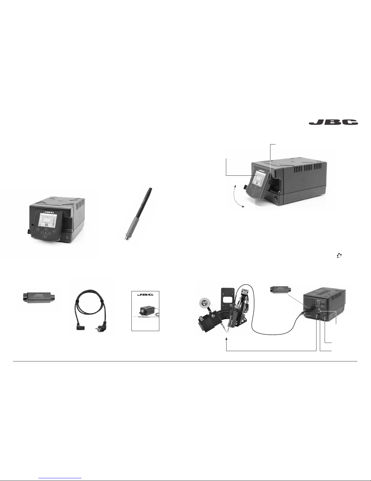
1. Connect the tool to the stati on port by means of the Converter.
2. Connec t your Robot system to the Ro bot connector (RJ12) of the station.
DB9-RJ12 Adapater available only if necessa ry (Ref: 0013772).
3. Enable the Ro bot option in the statio n settings and the notification w ill be displayed:
4. Set your Robot’s commands according to the Robot Communication Protocol, available on the website
www.jbctools.com/jbcsoftware-menu-115.html.
Manage and m onitor the station u sing a Robotic system.
Working with Robots
Control Un it
Ref. HDE-A
Robot Converte r
Ref. 0002747
Converte r .........................1 unit
Ref. 0002747
RS-232
connectio n
USB-A
connector
Tilt the display for
easy reading
2.8” Color TFT scr een
with capacitive keyboard
Features
USB-B
connector
Equipotential
connection
Power Socket
Page 3
ww w.jb ct oo ls. co m
ø 1
ø 3,5
A
B
4 5
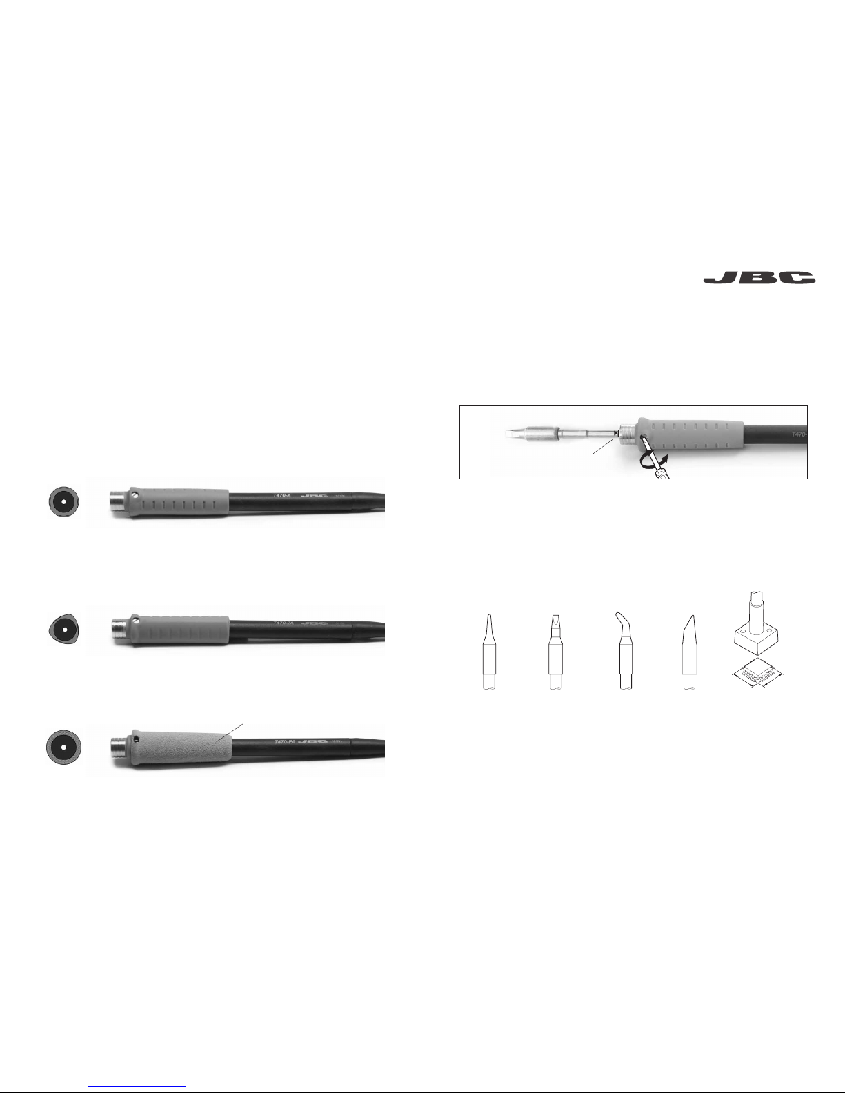
T470: Handles for Heavy Duty
Use C470 Ca rtridge range
HD General Purposes
Ref. T470-A
HD General Purposes with 3m cable
Ref. T470-SA
HD Thermal Insulatior
Ref. T470-FA
HD Thermal Insulatior with 3m cable
Ref. T470-MA
Tri-lobed
Ref. T470-ZA
For better handling of the tool.
For intensive soldering jobs requiring continued high thermal power. They feature a non-slip-grip with
a good thermal insulation and a screw which fixes the cartridge and prevents rotation.
Note: All models are supplied with a 1.5m cable except those specified with 3m.
Compatible Soldering Iron Handles
Foam
Mark
Before changing the cartridge, be sure that the tip is cold.
Once the cartridge is properly inserted we recommend tightening the screw to prevent moving.
*Impor tant: It is essential to insert the cartridges as far as the mark for a good connection.
Compatible Cartridges
The HDRE-A works w ith C470 cartridge s and T470 Handles. Find the model tha t best suits your
solderin g needs in ww w.jbctools.co m
Round Chisel Round bent Bevel Special mo dels
Changing and fixing the cartridges
JBC offers a w ide range of handles and grips to ch oose from.
Page 4

MENU INFO
OK
350
ºC
Port
2
Power
45%
Temp. Levels
250 350 380
17:14
T470
MENU
OK
Port 1 - T245
450
400
350
300
250
150
100
50
200
Power Temp
17:14
ww w.jb ct oo ls. co m
6 7
USB flash drive is connected.
Station is controlled by a PC.
Station is controlled by a robot.
Station software update.
Press INFO to start the process.
Warning.
Press INFO for failure description.
Error. Press INFO for failure description,
the type of error and how to proceed.
System notifications (Status Bar)Menu Options
Station
Information
Power
indicator
Tool
connected
Work Screen
Status Bar
The HDE-A offers an intuitive user interface which provides quick access to the station parameters.
Change
port
Displayed if
temperature
levels are
activated
Station Tools Counters
ResetGraphicsPeripherals
Press INFO for each parameter description.
By pressing Graphics in the main MENU, temperature an d power response s in
real time are di splayed for each p ort. This helps you decide which the proper tip is
for every soldering job and the quality of the solder joint.
Process analysis
Export graphics
Insert a US B flash drive into the US B-A
connector to sta rt saving you r soldering
process in c sv format.
Graphics
Temperature
Power (%)
See other
port graphic
Page 5

ww w.jb ct oo ls. co m
8 9
Update the station software
1. Download the JBC Update File softwa re from
www.jbcto ols.com/sof tware.html and save it on
a USB flash dr ive. Preferably one with no other fil es.
JBC
Update File
2. Inser t the USB flash dri ve.
The icon is diplayed while updating.
Soldering Net
Remotely man age and monitor as m any stations as you r Windows PC can ha ndle.
any JBC station
JBC
Manager
softwa re
USB Hub
Clean periodically
Maintenance
Before carr ying out mai ntenance or storag e, always allow the equipment to cool.
- Clean the station screen with a g lass cleane r
or a damp cloth.
1. Pull off the fuse holder and remove th e fuse.
If necess ary use a tool to lever i t off.
2. Press the new fuse into the fuse ho lder
and replace i t in the station.
- Use a damp cloth to cl ean the casing a nd
the tool. Alcoh ol can only be use d to clean
the metal par ts.
- Periodica lly check that th e metal parts of
the tool are clea n so that the station c an
detect the tool sta tus.
Fuse holder
Fuse holder
- Maintain tip s urface cle an and tinned pr ior
to storage in order to avoi d tip oxidation.
Rusty and dirty sur faces reduce h eat
transfer to the so lder joint.
- Periodica lly check all c ables and tubes.
- Replace a bl own fuse as follows:
Fuse
- Replace any d efective or dama ged pieces. Us e original JBC s pare parts on ly.
- Repairs sh ould only be performed by a JBC a uthorized techn ical serv ice.
Functions:
- Set all the stati on parameters
from your PC.
- Organize groups of stations and
set all their pa rameters at the
same time.
- Store specif ic configur ations for
later uses.
- Analyze th e soldering gr aphics
of the stations on yo ur PC and
export the m.
1. Download the JBC Manager software and the user manual from www.jbctools.com/manager.html
2. Connect th e stations via USB -B connector an d the PC will automatically detect the m.
3. The notific ation will be dis played on the station.
Page 6

ww w.jb ct oo ls. co m
10 11
Safety
It is impe rative to f ollow safe ty guid elines to p revent ele ctric
shock, i njury, fi re or explo sion.
- Do not use the uni ts for any purpose other than solde ring or rework. Inc orrect use may c ause fire.
- The power cord must be plugged into approved bases. Be sure that it is properly grounded
before use. When unp lugging it, hold th e plug, not the wire.
- Do not work on ele ctrically li ve parts.
- The solderi ng tip and the metal p art of the tool may sti ll be hot even when the station is turned off.
Handle with care.
- Do not leave the ap pliance unat tended when it i s on.
- Do not cover the ven tilation grills. H eat can cause i nflamable products to ignite.
- Use a “non resid ue” classifi ed flux and avoid c ontact with skin or eyes to prevent irritation.
- Be careful with the fumes prod uced when sol dering.
- Keep your work place clean a nd tidy. Wear appropria te protective glasse s and gloves whe n
work ing to avoid person al harm.
- Utmost care mu st be taken with liq uid tin waste which c an cause burn s.
- This appli ance can be use d by children over the a ge of eight and als o persons with re duced
physi cal, sensor y or mental capabilities or la ck of experienc e provided that they have been given
adeq uate superv ision or instru ction concer ning use of the appliance and und erstand the ha zards
involved. Children mus t not play with the app liance.
- Maintenanc e must not be carr ied out by childr en unless sup ervised.
Exploded View
Page 7

0015305-0115
Warranty
JBC’s 2 year warranty covers this equipment
against all manufacturing defects, including the
replacement of defective parts and labour.
Warranty does not cover product wear due to use
or mis-use.
In order for the warranty to be valid, equipment
must be returned, postage paid, to the dealer
where it was purchased.
This product should not be thrown in the garbage.
In accordance with the European directive 2002/96/EC, electronic equipment at the end of their life
must be collected and returned to an authorized recycling facility.
HDE-1A 120V 50/60Hz. Input fuse: 4A. Output: 47V
HDE-2A 230V 50/60Hz. Input fuse: 2A. Output: 47V
HDE-9A 100V 50/60Hz. Input fuse: 4A. Output: 47V
- Weight: 5.9 Kg (13.1 lb)
- Dimensions: 145 x 120 x 225 mm
- Output Peak Power: 250W
- Temperature Range: 90-500 ºC (190-932 ºF)
- Idle Temp. Stability (still air) ±1.5 ºC (±3 ºF)
- Tip to ground resistance: <2 ohms
- Tip to ground voltage: <2mV RMS
- Ambient Operating Temperature: 10-40 ºC (50-104 ºF)
- USB-A / USB-B / Peripherals connectors
- RJ12 connector for Robot
Complies with CE standards
ESD protected housing “skin effect”
Specifications
www.jbctools.com
 Loading...