

Page 1

ww w.jbctools.com
English
Fume Extractor Switch
Ref. FSE-A
Page 2
www.jb c to o l s.c om
Packing List
The following items should be included:
Fume Extractor Switch ........................ 1 unit
Ref. FSE-A
Power Cord .............................................. 1 unit
Ref. 0009417 (100V/120V)
0009401 (230V)
Adapter ..................................................... 1 unit
Ref. 0009295
Module Cable ......................................... 1 unit
Ref. 0014874
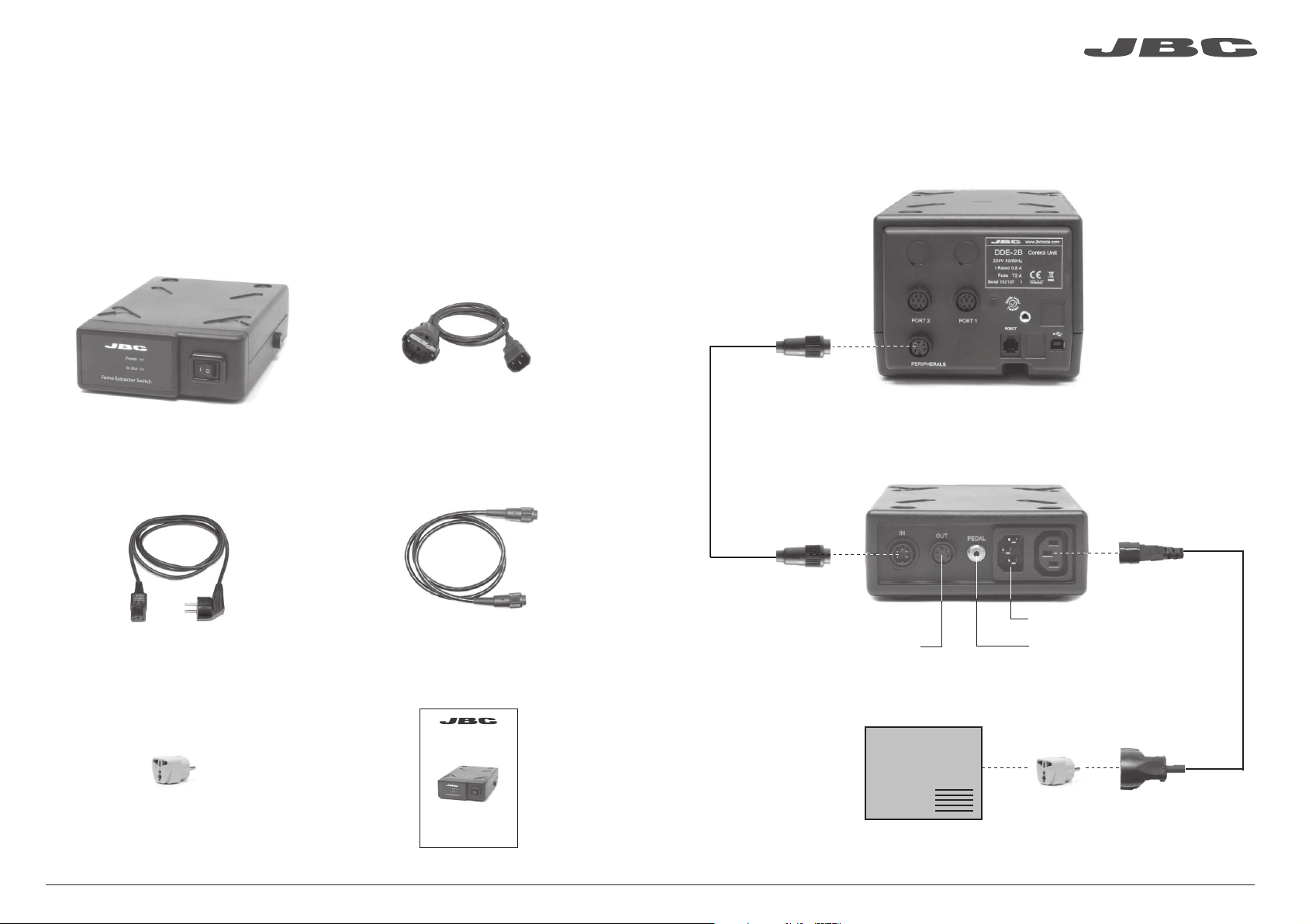
Features
Module cable
Ref. 0014874
Control Unit
Ref. DDE / DME / HDE
Fume Extractor Switch
Ref. FSE-A
Power socket
Plug adapter ............................................ 1 unit
Ref. 0006257
Manual ..................................................... 1 unit
Ref. 0014774
To another
peripheral
To Pedal
Ref. P-005
Adapter
Ref. 0009295
Only supplied with FSE-1A
www.j bct ools .co m
Fume Extractor
Plug Adapter
Fume Extractor Switch
Ref. FSE-A
Ref. 0006257
Only if necessary
2 3
Page 3

www.jb c to o l s.c om
Initial Set up
For DDE Control Unit
1. Once it is set up, enter the Peripherals
Menu and select a port to connect the FSE.
2. Select the FSE from the list. Remember
your first connection is denoted as “a”, the
second being “b”, etc. (e.g. FSE_a, FSE_b,...)
3. Press Menu or Back to save changes.
For DME Control Unit
When a new module is detected, a pop-up appears and proceed as indicated.
If nothing appears on the screen, click on the icon and follow the instructions.
17:14
Peripherals Port 2-T245
Pedal None
Module None
MENU
?
Module
FSE_a
None
17:14
It disappears
when the
installation is
completed
Operation
1. When the tool is lifted from the stand the fume extractor is automatically activated.
2. When the tool is returned to the stand the fume extractor stops. Tool temperature drops to go into
Sleep mode.
The red light
indicates the FSE
is ready
The green light indicates
the FSE is in use
Accessories
MODULE
Fume Extractor
Install
For DME and DDE Control Units
Once configured, you can change the FSE settings by entering the Peripherals Menu.
Postpone
Fume extractor tube
See the different models on the website.
This tube is an easy & safe solution to
remove the fumes generated at the solder
joint. It requires a fume extractor.
Use this foot switch to enable/disable a
module or make the tool enter/exit Sleep mode.
Pedal
Ref. P-005
4 5
Page 4

www.jb c to o l s.c om
Maintenance
Before carrying out maintenance or storage, always unplug the equipment.
- Clean the casing with a damp cloth. Make sure to use a soft cloth when cleaning the front.
- Periodically check the cables and tubes.
- Replace a blown fuse as follows:
Fuse
Fuse holder
1. Loosen the black cap to remove the fuse.
- Replace any defective or damaged pieces. Use original JBC spare par ts only.
- Repairs should only be per formed by a JBC authorized technical service.
2. Fit the new fuse into the holder and
screw back into the module.
Exploded View
Safety
It is imperative to follow safety guidelines to prevent electric
shock , injury, fire or explosion.
- Only fume extractors can be used with the fume extractor switch.
- Do not use the soldering stations for any purpose other than soldering or rework. Incorrect use
may cause fire.
- The power cord must be plugged into approved bases. Be sure that it is properly grounded
before use. When unplugging it, hold the plug, not the wire.
- Do not work on electrically live parts.
- The soldering tip, the stand and the metal part of the tool may still be hot even when the station
has been turned off. Handle with care.
- Do not leave the appliance unattended when it is on.
- Do not cover the ventilation grills. Heat can cause inflamable products to ignite.
- Use a “non residue” classified flux and avoid contact with skin or eyes to prevent irritation.
- Be careful of the fumes produced when soldering.
- Keep your workplace clean and tidy. Wear appropriate protective glasses and gloves when
working to avoid personal harm.
- Utmost care must be taken with liquid tin waste which can cause burns.
- This appliance can be used by children over the age of eight and also persons with reduced
physical, sensory or mental capabilities or lack of experience provided that they have been given
adequate supervision or instruction concerning use of the appliance and understand the hazards
involved. Children must not play with the appliance.
- Maintenance must not be carried out by children unless supervised.
6 7
Page 5

Specifications
Fume Extractor Switch
Ref. FSE-1A (120 V) / FSE-2A (230 V)
FSE-A
- Weight: 1.2 Kg (2.6lb)
- Size: 145 x 55 x 210 mm
- Voltage: 24V (from control unit)
- Fuse: 5A T
- Ambient operating temp: 10-40 ºC / 50-104 ºF
Complies with CE standards
ESD protected housing “skin effect”
Warranty
JBC’s 2 year warranty covers this equipment
against all manufacturing defects, including the
replacement of defective parts and labour.
Warrant y does not cover product wear due to use
or mis-use.
In order for the warranty to be valid, equipment
must be returned, postage paid, to the dealer
where it was purchased.
This product should not be thrown in the garbage.
In accordance with the European directive 2002/96/EC, electronic equipment at the end of their life
must be collected and returned to an authorized recycling facility.
www.jbctools.com
0014777-0415
 Loading...