

Page 1
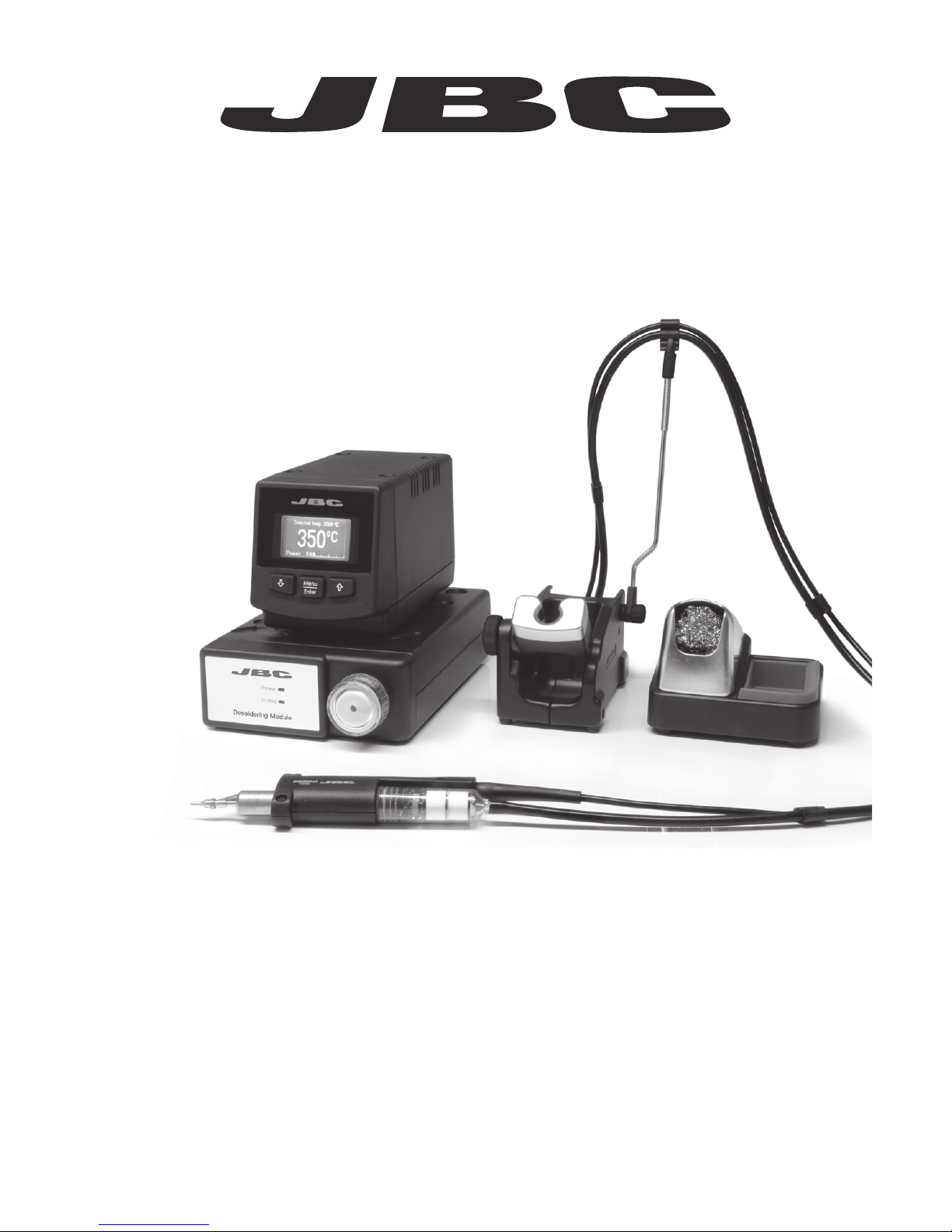
Premium
Micro Desoldering station
Ref. DSS-D
English
www.jbctools.com
Page 2
2
Packing List
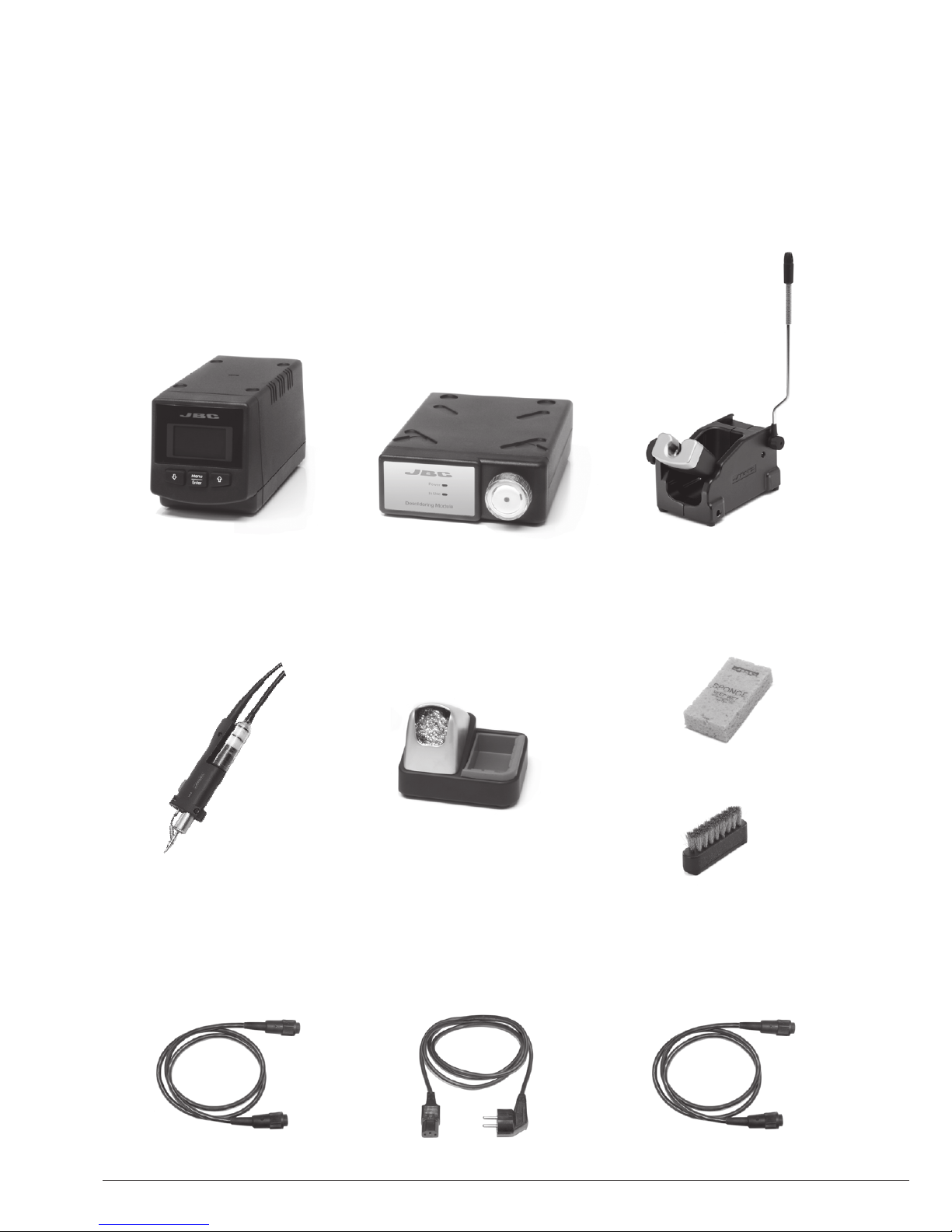
The following items should be included:
DI Control Unit .............. 1 unit
Ref. DI-1D (120V)
DI-2D (230V)
DI-9D (100V)
Micro
Desoldering Iron............ 1 unit
Ref. DS360-A
Support Cable
connector ....................... 1 unit
Ref. 0011283
Stand ............................... 1 unit
Ref. DS-SD
Sponge ........................... 1 unit
Ref. S0354
Brush ............................. 1 unit
Ref. CL6217
Electric Desoldering
Module............................. 1 unit
Ref. MS-A
Tip Cleaning
Stand ............................... 1 unit
Ref. CL9885
Power cord ..................... 1 unit
Ref. 0009417 (100V/120V)
0009401 (230V)
Module Cable
connector ...................... 1 unit
Ref. 0010207
Page 3
3
Manual ...........................................................1 unit
Premium
Micro Desoldering station
Ref. DSS-D
Suction Filter ................................................. 1 unit
Ref. 0821830
Cotton Filter .............. 10 units
Ref. 0781046
Filter Box ......................... 1 unit
Ref. 0005966
It contains 50 filters
Cable flange.................. 2 units
Ref. 0010154
Tips
(5 units)
Ref. C360002
Tips
(5 units)
Ref. C360004
Cleaning Rods
Ref. 0008466
Filter
(2 units)
Ref. 0008473
Cleaning brush
Ref. 0008297
Solder Collector
(2 units)
Ref. 0008467
DS360-A Accessories
Ref. 0010259
ww w.j b c tools.com
www .jbc tool s.c om
Page 4
4
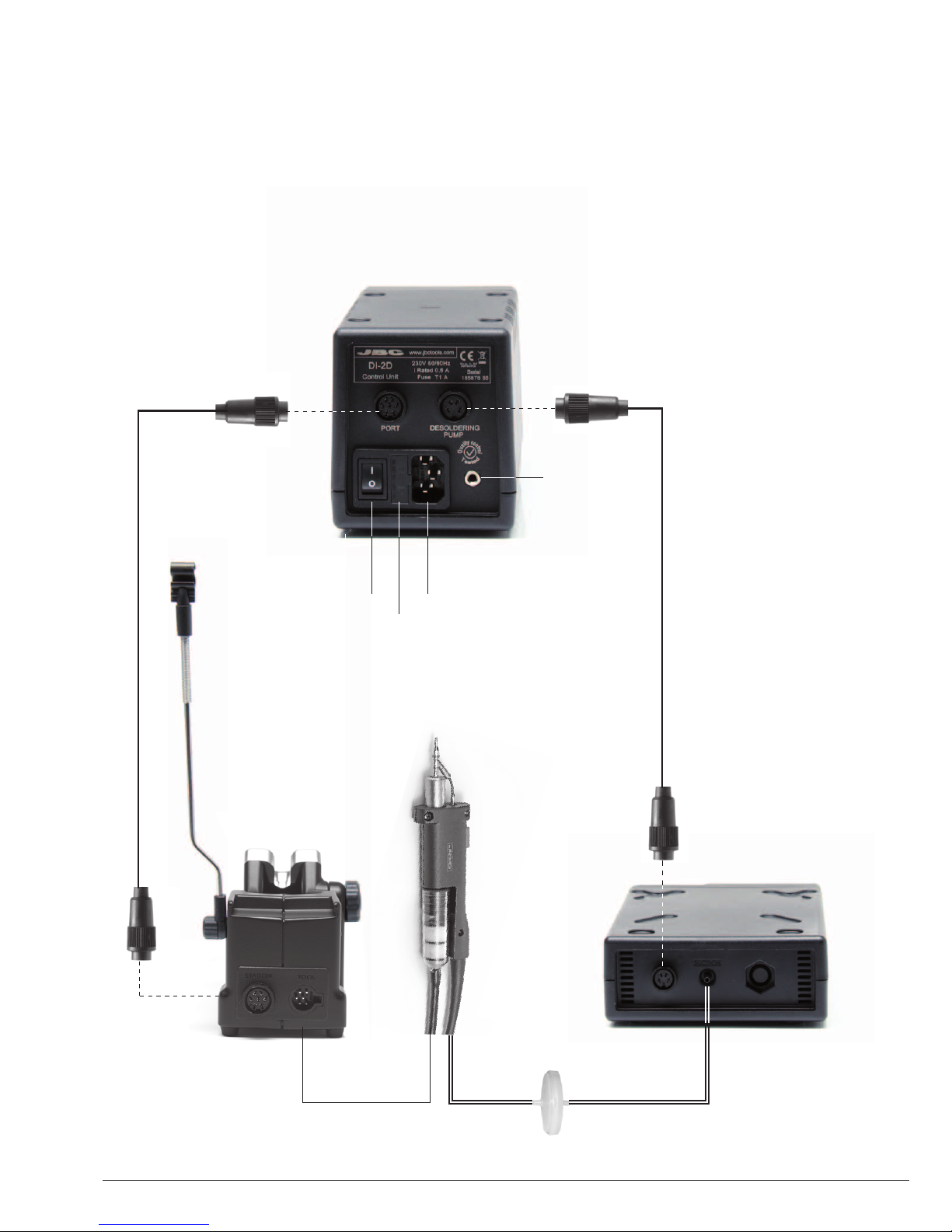
Features
Support Cable
connection
Ref. 0011283
DI Control Unit
Ref. DI-1D (120V)
DI-2D (230V)
DI-9D (100V)
Micro Desoldering Iron
Ref. DS360-A
Suction Filter
Ref. 0821830
Stand
Ref. DS-SD Electric
Desoldering
Module
Ref. MS-A
Main switch
Fuse
Equipotential
connection
Power Socket
Module Cable
connector
Ref. 0010207
Page 5
5
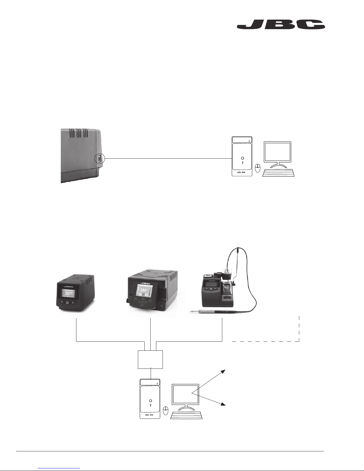
USB Connector
JBC Updater
JBC Manager
Download the latest softwares from our website to improve your soldering station.
www.jbctools.com/software.html
Update the station software via USB connection:
www.jbctools.com/manager.html
Manage and monitor as many stations as your Windows PC supports by using the JBC Manager.
You can export data to another PCs.
Manager Settings
Change settings for a group
of JBC stations at the same
time.
Register Settings
Create graphs of the
soldering process in real time
with power and temperature
data.
Cable USB AB
Cable
USB AB
any JBC
station
USB
Hub
JBC
Manager
ww w.j b c tools.com
Page 6

6
Operation
The JBC Exclusive Heating System
This revolutionary technology is able to recover tip temperature extremely quickly.
This allows the user to work at a lower temperature.
As a result, tip life increases x5 times.
1. Work
Lift tool from the stand and
the tool tip will heat up to the
selected temperature.
2. Sleep
When the tool is in the stand,
the temperature reduces to
Sleep temperature (pre-set
260ºC / 500ºF).
Tool in the stand
A ct u al Te m p. 2 6 0oC
Sleep
Tool in the stand after sleep
No heat
A ct u al Te m p. 2 0oC
Hibernation
0
c
Selected temp.
350 oC
P ow e r 1 0%
350
Long time
in the stand
3. Hibernation
After long periods in the stand
(pre-set 30 min), the power is cut
and the tool cools down to room
temperature.
Change temperature
(from 90 to 450ºC)
Tool Settings:
· Select temperature levels
· Fix one temperature
Tool Settings:
· Set Sleep temperature
(from 180 to 450ºC)
· Set Sleep delay
(from 0 to 9 min or no Sleep)
Tool Settings:
· Set Hibernation delay
(from 0 to 35 min or no
hibernation)
Page 7

7
Menu Screen
Mai n me nu
Cou nt er s
Too l se tt in gs
4 Counters
5
Program version
4
Hibernation hours 0
5
No tool hours 0
6 Sleep cycles
0
7 Desold cycles
0
4
Sleep temp 2600C
5
Hibernation delay 30 min
6
Temp adjust + O OC
Tool DS
Tool
DS
Bac kBac k
Sta ti on set ti ng s
Bac k
Original PIN: 0105
This screen provides
useful information of tool
status in real time.
0
c
Selected temp.
350 oC
P ow e r 1 0%
Fixed temp.
350 oC
Displays a specific fixed temp.
Shown when you have
selected temp. levels.
Work Screen
Process Control
1
Fix one temp -----
2
Temp levels set OFF
3
Sleep delay 0 min
5 Beep ON
6
Change PIN
1 Temp unit
Celsius
2
Maximum temp 4000C
3
Minimum temp 2000C
4
Help text OFF
Levels ºC
270 35 0 4 00
1
Plugged hours 0
2
Working hours 0
3
Sleep hours 0
350
Exit
1 Reset settings
2
Station settings
3
Tool settings
ww w.j b c tools.com
Page 8

8
Cable collector
Keeps working area
free of cable.
Adjustable tool holder
Suits your work position.
Adjustable
cable collector
Stand assembly
Page 9

9
Improve thermal transfer by cleaning the tip after each solder joint.
Tip Cleaning stand
Optional
Brass wool
Ref. CL6210
Inox wool
Ref. CL6205
Brushes
Ref. CL6220
Tip-tinner
Ref. TT-A
Sand
Ref. CL6211
Splashguard
Non-slip base
Sponge
Ref. S0354
Wiper
Ref. CL0236
Very effective cleaning
method. It leaves a small layer
of solder on the tip to prevent
oxidation between cleaning
and rewetting.
It minimises splashing
of solder particles
when using the metal
or brass wool. You don’t need to
hold the base while
cleaning tips
The least harmful cleaning
method. Keep the sponge damp
with destilled water when working
to avoid tip wear.
A temperature resistant receptacle
allows the operator to remove excess
solder by gently tapping or wiping.
Wiper can be easily removed to clean it.
Tapping: Wiping:
Tap gently to remove
the excess of solder.
Use the slots to wipe
off any remaining
particles.
ww w.j b c tools.com
Page 10

10
A ø
B ø
C360-003
ØA: 1.4
ØB: 1
Ømax.pin: 0.8
C360-002
ØA: 1.2
ØB: 0.8
Ømax.pin: 0.6
C360-004
ØA: 1.4
ØB: 1
Ømax.pin: 0.8
Important:
Change tips only when the tool is hot, so that
any solder left inside is in molten state.
Ø Inner nozzle
Ø Pin
C360-001
ØA: 1
ØB: 0.8
Ømax.pin: 0.4
C360-007
ØA: 1.9
ØB: 1.4
Ømax.pin: 1.2
C360-006
ØA: 3
ØB: 1.5
Ømax.pin: 1.3
Do not hold the tip on the spring clamp.
Changing the Tip
1. Remove the tip by using a flat-nosed pliers.
Twist the tip and pull.
Compatible tips
The CS and CV desoldering stations work with C360 tip range. Find the model that best suits your
desoldering needs on www.jbctools.com
Tip selection
Remember to select the biggest tip possible for your application: Ø Inner nozzle > Ø Pin.
2. Insert the new tip and follow the same steps
conversely.
Page 11

Spare filters
Ref. 0005966
Cotton filters
Ref. 0781046
Suction filter
Ref. 0821830
Important:
Do not open the
Suction filter with
sharp pointed
objects in order
to avoid damage.
O Ring
Ref. 0007717
Filter cover
Ref. 0004710
11
Changing the Heating Element
Filter
Fixing screw
Heating element
Ref. DSV-DS
1. Disconnect the tool. Pull off the filter and the solder collector.
2. Undo the fixing screw indicated in the picture and remove the heating element.
3. Insert the new heating element following the same steps conversely.
Changing the Pump Filters
Solder Collector
ww w.j b c tools.com
Page 12

12
Remove the fuse by pulling the black cap.
If necessary use a tool to lever it off.
Press the new fuse into the holder and
replace it in the station.
Maintenance
Fuse
Before carrying out maintenance or storage, always allow the equipment to cool.
- Clean the station’s screen with a glass
cleaner or a damp cloth.
- Use a damp cloth to clean the casing and
the tool. Alcohol can only be used when
cleaning the metal parts.
- Periodically check that the metal parts of
the tool/stand are clean so that the station
can detect when the tool is in the stand.
- Maintain tip surface clean and tinned prior
to storage in order to avoid tip oxidation.
Rusty and dirty surfaces reduce heat
transfer to the solder joint.
- Periodically check all cables, tubes and
filters to ensure proper solder suction.
- Replace a blown fuse as follows:
- Replace any defective or damaged pieces. Use original JBC spare parts only.
- Repairs should only be performed by a JBC authorized technical service.
Clean periodically
Page 13

13
- Do not use the equipment for any purpose other than soldering or rework. Incorrect use may
cause fire.
- The power cord must be plugged into approved bases. Be sure that it is properly grounded
before use. When removing it, hold the plug, not the wire.
- Do not work on electrically live parts. Antistatic handle of soldering irons is electrically
conductive.
- The tool should be placed in the stand when not in use in order to activate the sleep mode.
The soldering tip, the metal part of the tool and the stand may still be hot even when the station is
turned off. Handle with care, including when adjusting the stand position.
- Do not leave the appliance unattended when it is on.
- It is necessary to turn the station off before changing tips.
- Do not cover the ventilation grills.
- Heat can cause inflamable products to ignite even when out of sight.
- Use a “non residue” classified flux and avoid contact with skin or eyes to prevent irritation.
- Be careful with the fumes produced when soldering.
- Keep your workplace clean and tidy. Wear appropriate protection glasses and gloves when
working to avoid personal harm.
- Utmost care must be taken with liquid tin waste which can cause burns.
- This appliance can be used by children over the age of eight and also persons with reduced
physical, sensory or mental capabilities or lack of experience provided that they have been given
adequate supervision or instruction concerning use of the appliance and understand the hazards
involved. Children must not play with the appliance. Maintenance shall not be carried out by
children unless supervised.
Safety
It is imperative to follow safety guidelines to prevent electric
shock, injury, fire or explosion.
ww w.j b c tools.com
Page 14

14
Exploded View
Page 15

15
ww w.j b c tools.com
Page 16

0014655-0814
Warranty
JBC’s 2 year warranty covers this equipment
against all manufacturing defects, including the
replacement of defective parts and labour.
Warranty does not cover product wear due to use
or mis-use.
In order for the warranty to be valid, equipment
must be returned, postage paid, to the dealer
where it was purchased.
This product should not be thrown in the garbage.
In accordance with the European directive 2002/96/EC, electronic equipment at the end of their life
must be collected and returned to an authorized recycling facility.
Specifications
DI-1D 120V 50/60Hz. Input fuse: 2A. Output: 23.5V.
DI-2D 230V 50/60Hz. Input fuse: 1A. Output: 23.5V.
DI-9D 100V 50/60Hz. Input fuse: 2.5A. Output: 23.5V.
- Total unit weight: 4,4 kg (9.6 lb)
- Size: 90 x 105 x 180 mm
- Temperature selection from 90°C (190°F) to 450°C (840°F)
- Output Peak Power: 130W
- Tip to ground resistance: <2 ohms
- Ambient operating temp: 10-40 ºC / 50-104 ºF
- USB connector station-PC
MS-A
- Total weight and size: 1,2 Kg (2.6lb)
- Size: 145 x 55 x 225 mm
- Vacuum: 75% / 570 mmHg / 22.4 inHg
- Flow rate: 9 SLPM
Complies with CE standards
ESD protected housing “skin effect”
www.jbctools.com
 Loading...