

Page 1
Index Page
English 1
Español 7
Français 13
Deutsch 19
Italiano 25
DI 2860
DIGITAL SOLDERING STATION
Instructions manual
Page 2

Page 3
ENGLISH
1
We appreciate the trust you have placed in JBC in purchasing this station. It is
manufactured to the most strictest quality standards in order to give you the best
possible service. Before turning on your station, we recommend you read these
instructions carefully.
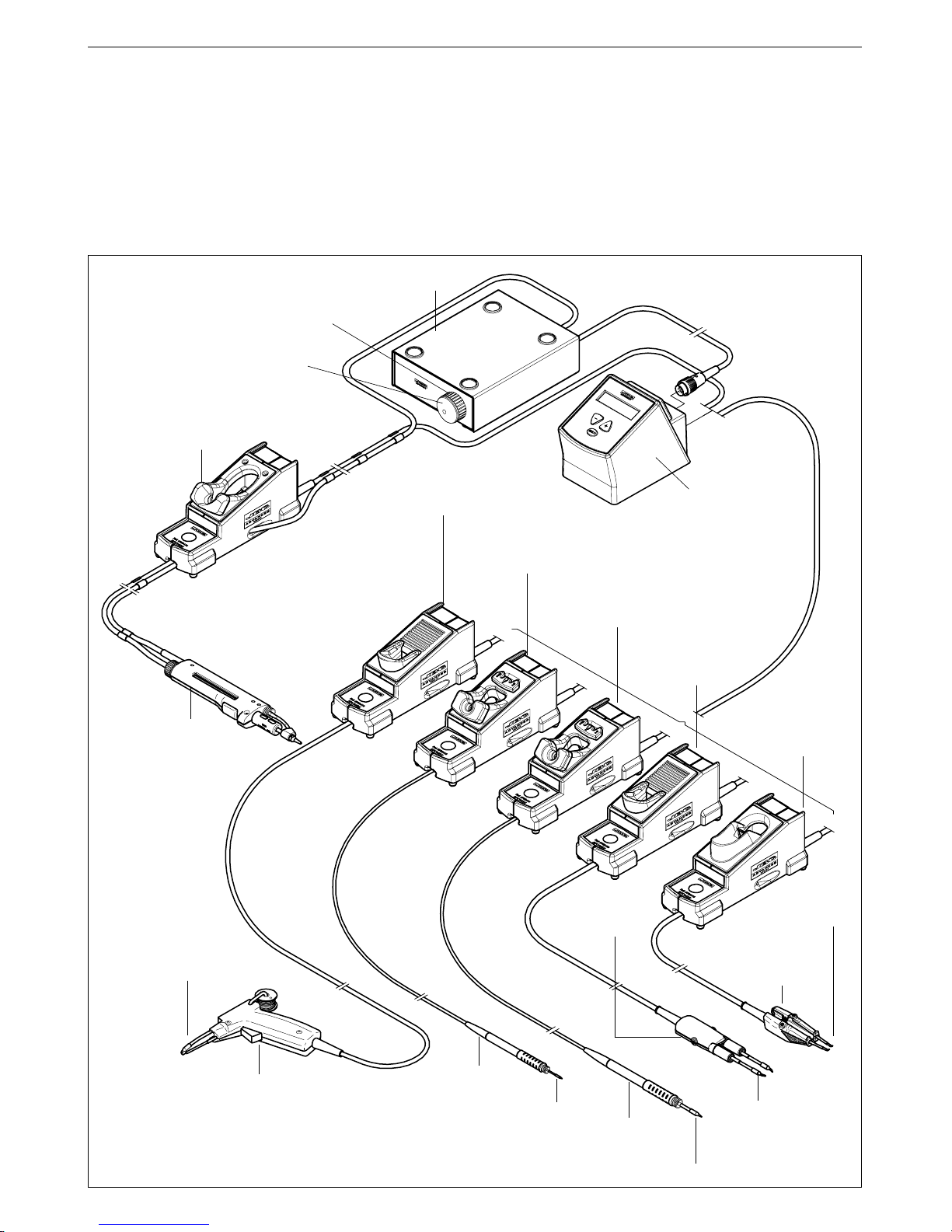
You have purchased an Advanced DI 2860 digital soldering control unit.
In order to complete the soldering station you should choose the necessary elements for the task
to carry out.
* Cartridges for the
PA 4200 hot
tweezers
* PA 1200
micro hot tweezers
Ref. 1200000
* 1200 cartridges
* PA 8110
hot tweezers
stand
Ref. 0748110
Control Unit
DI 2860 230V Ref. 2860200
DI 2860 120V Ref. 2860100
DI 2860 100V Ref. 2860109
* PA 8120
hot tweezers stand
Ref. 0748120
* PA 4200
hot tweezers
Ref. 4200000
* These elements are not supplied with
the control unit
* AP 8130
solder feed iron stand
Ref. 0788130
* 2210 handpiece
Ref. 2210000
* 2210 cartridges
* 2245 cartridges
* AD 8245
soldering iron stand
Ref. 0788245
* AD 8210
soldering iron stand
Ref. 0788210
* AP 1300
solder feed iron
Ref. 1300000
* 1300 cartridges
* DR 5650
desoldering iron
Ref.5650000
Spare filters
Ref.0005966
* DR 8500
desoldering iron stand
Ref.0788500
* Electric desoldering pump MS 9014 Ref.9014000
* Air pressure desoldering system MS 9015 Ref.9015000
* 2245 handpiece
Ref. 2245000
Desoldering air filter
Page 4

ENGLISH
2
DI 2860 digital control unit
- DI 2860 230V Ref. 2860200
- DI 2860 120V Ref. 2860100
- DI 2860 100V Ref. 2860109
You can connect this unit to all the tools of our
Advanced series but always using its
corresponding stand, including the DR 5650
desoldering iron by adding the electric
desoldering pump MS 9014 Ref. 9014000 or the
air pressure desoldering system MS 9015 Ref.
9015000.
The station's components:
DI 2860 230V Ref. 2860200
- DI 2860 230V control unit
- Connection cable to mains Ref. 0269300
- Instructions manual
DI 2860 120V Ref. 2860100
- DI 2860 120V control unit
- Connection cable to mains Ref. 0269320
- Instructions manual
DI 2860 100V Ref. 2860109
- DI 2860 100V control unit
- Connection cable to mains Ref. 0269320
- Instructions manual
Kit DI 2860 -2245 230V Ref.2860230
- DI 2860 230V control unit Ref. 2860200
- 2245 handpiece Ref. 2245000
- AD 8245 stand Ref. 0788245
- 2245-003 cartridge Ref. 2245003
Kit DI 2860 -2210 230V Ref.2860231
- DI 2860 230V control unit Ref. 2860200
- 2210 handpiece Ref. 2210000
- AD 8210 stand Ref. 0788210
- 2210-001 cartridge Ref. 2210001
Speak to your distributor for more kits.
Technical specifications
- Temperature selection from 90 to 450°C or
190 to 840°F (±5%).
- Power: 75W.
- Safety transformer, mains separator and
double isolation, with integrated temperature
protection fuse.
- DI 2860 230V control unit Ref. 2860200
Input: 230V 50Hz. Output: 24V.
- DI 2860 120V control unit Ref. 2860100
Input: 120V 60Hz. Output: 24V.
- DI 2860 100V control unit Ref. 2860109
Input: 100V±10% 50/60Hz. Output: 24V.
- Total weight of unit: 2,5Kg (6,25lbs).
- ESD protected housing "skin effect".
Typical surface resistance: 105-1011Ohms/
square.
- Complies with CE standards on electrical
safety, electromagnetic compatibility and
antistatic protection.
- RoHS compliant.
- Equipotential connector and the tool tip are
connected to station mains ground supply for
ESD protection.
This product should not be thrown in the
garbadge.
RECOMMENDATIONS FOR USE
For soldering
- Preferably select a temperature below
350°C (662ºF). Excess temperature reduce
tip life.
- The tip must be well tinned for good heat
conduction.
Safety measures
- Place the tool back on its stand in order to
let it cool down before you store it.
Page 5
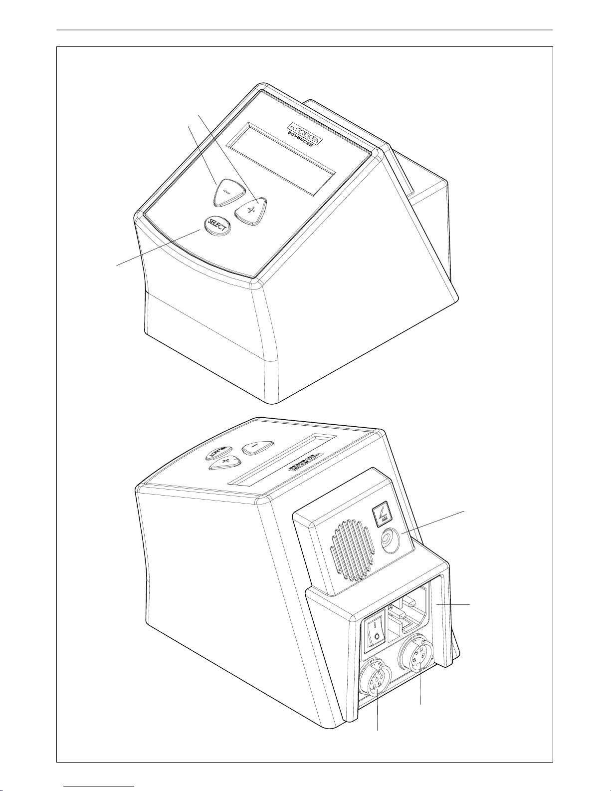
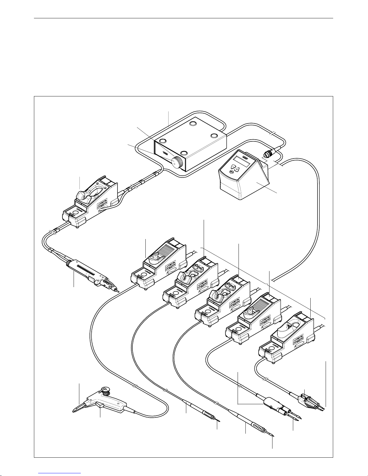
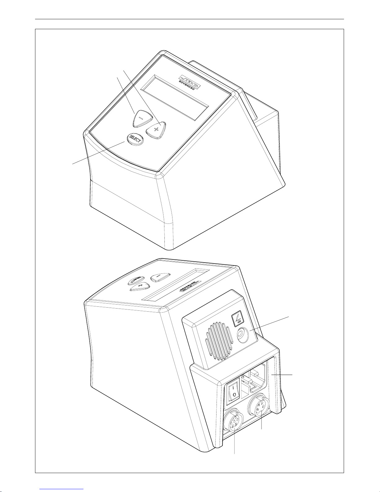
Tool connector
Power
connection
Equipotential connector
Desoldering pump
connector
See the
selected
temperature
Increases and
decreases the
temperature
DI 2860 single tool control unit
ENGLISH
3
Page 6
ENGLISH
4
PROGRAMMING
The system allows you to modify and adjust the
temperature between 90 and 450ºC (190 and
840ºF). These are the factory pre-selected
temperatures:
- Minimum temperature: 90ºC
- Maximum temperature: 400ºC
In order to modify the station and tool parameters
and have access to the counters, you must hold
the SELECT key for 3 seconds. The PIN number
must be entered when you need to change a
station parameter. Default PIN number: 0105.
You will find the operation diagrams are on the
following pages.
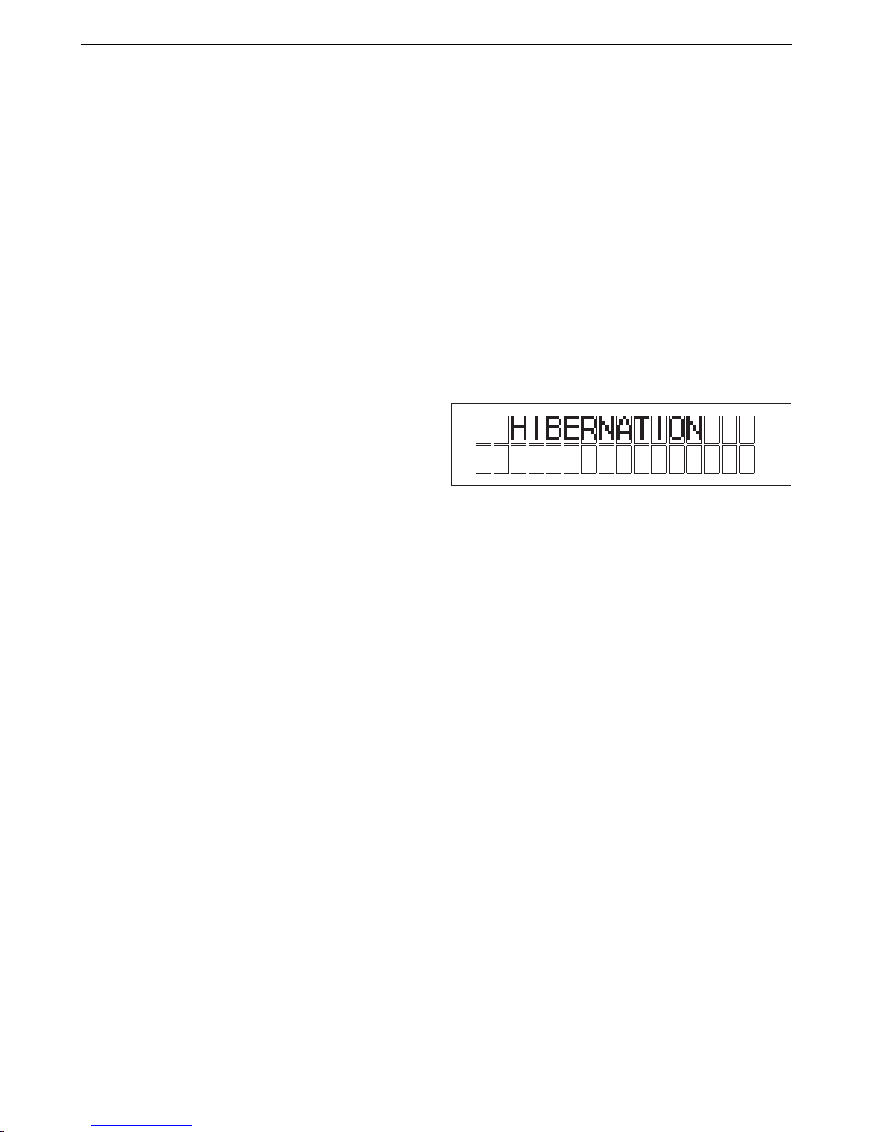
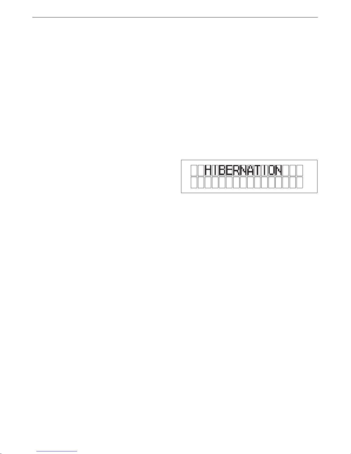
Display messages
- HIBERNATION: The station is in hibernation
mode.
- OPEN CIRCUIT. Heating element with open
circuit. Possible causes:
The cartridge has not been inserted correctly
in the tool.
Damaged cartridge.
- MAXIMUM POWER. The maximum available
power has been exceeded for too long - e.g.
in very thick and repetitive soldering jobs.
- SHORTCIRCUIT. Short circuit in the system.
Possible causes:
Short circuit in the cartridge or in the handpiece.
- WRONG TOOL.
Possible causes: use of a tool which is not
compatible with the station.
- OVERLOAD. To prevent the station from
overheating, you must wait and the station will
automatically reset.
Possible causes: excesive power demand.
Once you correct the above mentioned causes,
the station will start working automatically, except
if there is an excess in energy supply (MAXIMUM
POWER). In this case, the station has to be
switched off and restarted.
INTRODUCTION TO THE JBC ADVANCED
SYSTEM
The exclusive and new JBC microprocessor
driven heating system ensures such a fast heat
recovery that it enables performing at lower
temperatures than before and improving a 40%
the efficiency of the station.
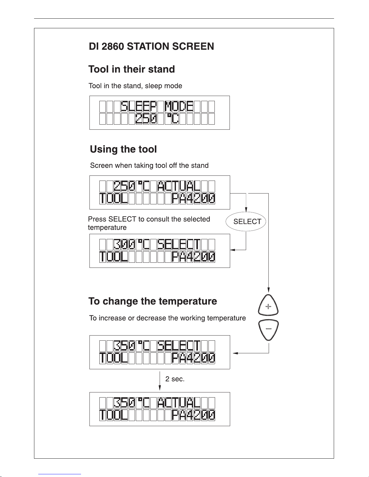
SLEEP FUNCTION
Tool in sleep mode
One feature of the Advanced series is that
when the tool is placed in the stand, the
temperature automatically drops to the sleep
temperature. This function is possible
because of the quick response time that
allows the user to switch from sleep
temperature to working temperature very
quickly. Thanks to the sleep mode, oxidation
levels at the tip are much lower and therefore
the tip life is extended 3 to 5 times.
The sleep function parameters can be
modified using the station program.
In order to take full advantage of the sleep
mode and as a security measure, it is
necessary to place the tool in the stand
when it is not being used.
Hibernation mode
Apart from the "SLEEP" mode the DI 2860 features
a hibernation mode.
In this mode the tool cools down to room
temperature but it goes back to working
temperature as soon it is picked up.
A tool can enter into hibernation mode after
entering into the "SLEEP" mode. Changing into
hibernation mode starts from the moment you are
in "SLEEP" mode.
Hibernation can be modified using the «SETUP»
sub menu. See page 32.
The tip life is directly related to the
temperature and time. With a greater
temperature for a longer time, the tip duration
is reduced in an exponential form.
Due to this, it is advisable to keep the soldering
iron in the support at sleep temperature (200ºC
approximately) to increase the tip life.
JBC reserves the right to make technical changes without prior
notification.
Page 7
ENGLISH
5
See the programm modification chart of the station parameters on page 32
Page 8

ENGLISH
6
DR 5650 DESOLDERING IRON
DI 2860 station allows you to connect the
DR 5650 desoldering iron Ref. 5650000
by adding the MS 9014 electric
desoldering pump Ref. 9014000 or the MS
9015 air pressure desoldering system Ref.
9015000.
For the desoldering iron to work properly,
the following components are required: the
control unit, the desoldering iron, a
desoldering pump module and the DR
8500 stand.
These articles are not included with the
station.
The desoldering iron is connected to the
station following the below procedure:
Connect the cable connection from the
desoldering iron to the plug in the DR 8500
desoldering iron stand, connect the
vacuum hose to the vacuum inlet of the
desoldering pump module.
The cable connection of the desoldering
iron stand must be connected to the tool
connector at the back of the station and
the cable connection of the desoldering
pump must be connected to the
desoldering pump connector.
DR 5650
desoldering iron
Ref.5650000
Heating element
Ref.5650010
DR 8500
desoldering iron stand
Ref.0788500
Desoldering air filter
Electric desoldering pump
MS 9014 Ref.9014000
Air pressure desoldering system
MS 9015 Ref.9015000
Tool connector
Desoldering pump
connector
Spare filters
Ref.0005966
Desoldering iron
vacuum inlet
Page 9
Agradecemos la confianza depositada en JBC al adquirir esta estación. Ha sido
fabricada con las más estrictas normas de calidad para prestarle el mejor servicio.
Antes de poner en marcha el aparato, recomendamos leer con atención las
instrucciones que a continuación se detallan.
Usted ha adquirido una unidad de control soldadora digital Advanced DI 2860.
Para que la estación soldadora esté completa debe elegir la herramienta, el soporte y los cartuchos
adecuados al trabajo a realizar.
7
ESPAÑOL
* Cartuchos para la
pinza PA 4200
* Micro pinza
desoldadora
PA 1200
Ref. 1200000
* Cartuchos 1200
* Soporte pinza
desoldadora
PA 8110
Ref. 0748110
Unidad de control
DI 2860 230V Ref. 2860200
DI 2860 120V Ref. 2860100
DI 2860 100V Ref. 2860109
* Soporte pinza
desoldadora
PA 8120
Ref. 0748120
* Pinza
desoldadora
PA 4200
Ref. 4200000
* Estos elementos no se suministran
con la unidad de control
* Soporte soldador con
aportación de estaño
AP 8130
Ref. 0788130
* Lápiz 2210
Ref. 2210000
* Cartuchos 2210
* Cartuchos 2245
* Soporte soldador
AD 8245
Ref. 0788245
* Soporte soldador
AD 8210
Ref. 0788210
* Soldador con aportación de
estaño AP 1300
Ref. 1300000
* Cartuchos 1300
Filtros de recambio
Ref.0005966
* Lápiz 2245
Ref. 2245000
* Desoldador DR 5650
Ref.5650000
* Soporte desoldador
DR 8500
Ref.0788500
* Bomba desoldadora eléctrica MS 9014 Ref.9014000
* Bomba desoldadora de aire comprimido MS 9015 Ref.9015000
Conjunto filtro aspiración
Page 10

Unidad de control digital DI 2860
- DI 2860 230V Ref. 2860200
- DI 2860 120V Ref. 2860100
- DI 2860 100V Ref. 2860109
Se pueden conectar a esta estación todas las
herramientas de nuestra gama Advanced usando
siempre su correspondiente soporte, incluso el
desoldador DR 5650 añadiendo la bomba
desoldadora eléctrica MS 9014 Ref. 9014000 o la
bomba desoldadora de aire comprimido MS 9015
Ref. 9015000.
ESPAÑOL
8
Datos técnicos
- Selección de la temperatura entre 90 y 450°C
o 190 a 840°F (±5%).
- Potencia: 75W.
- Transformador de seguridad, separador de
red y doble aislamiento, con fusible integrado
de protección temperatura.
- Unidad de control DI 2860 230V Ref. 2860200
Entrada: 230V 50Hz. Salida: 24V.
- Unidad de control DI 2860 120V Ref. 2860100
Entrada: 120V 60Hz. Salida: 24V.
- Unidad de control DI 2860 100V Ref. 2860109
Entrada: 100V±10% 50/60Hz. Salida: 24V.
- Peso unidad completa: 2,5Kg.
- Caja antiestática "skin effect".
Resistencia típica superficial: 105-1011 Ohms/
cuadro.
- Cumple la normativa CE sobre seguridad
eléctrica, compatibilidad electromagnética y
protección antiestática.
- Cumple la normativa RoHS.
- El borne equipotencial y la punta del soldador
están en conexión directa a la toma de tierra de
red para protección ESD.
Este producto no debe ser tirado a la
basura.
Composición de la estación:
DI 2860 230V Ref. 2860200
- Unidad de control DI 2860 230V
- Cable de conexión a red Ref. 0269300
- Manual de instrucciones
DI 2860 120V Ref. 2860100
- Unidad de control DI 2860 120V
- Cable de conexión a red Ref. 0269320
- Manual de instrucciones
DI 2860 100V Ref. 2860109
- Unidad de control DI 2860 100V
- Cable de conexión a red Ref. 0269320
- Manual de instrucciones
Kit DI 2860 -2245 230V Ref.2860230
- Unidad control DI 2860 230V Ref. 2860200
- Lápiz 2245 Ref. 2245000
- Soporte AD 8245 Ref. 0788245
- Cartucho 2245-003 Ref. 2245003
Kit DI 2860 -2210 230V Ref.2860231
- Unidad control DI 2860 230V Ref. 2860200
- Lápiz 2210 Ref. 2210000
- Soporte AD 8210 Ref. 0788210
- Cartucho 2210-001 Ref. 2210001
Existen más kits de esta estación, consulte a su
proveedor.
RECOMENDACIONES DE USO
Para soldar
- Con preferencia seleccione una temperatura
inferior a 350°C. El exceso de temperatura
reduce la vida de la punta.
- La punta debe estar bien estañada para
conducir bien el calor.
Medidas de seguridad
- Coloque la herramienta en su soporte
después de usarla y dejela enfriar antes de
almacenarla.
Page 11
9
ESPAÑOL
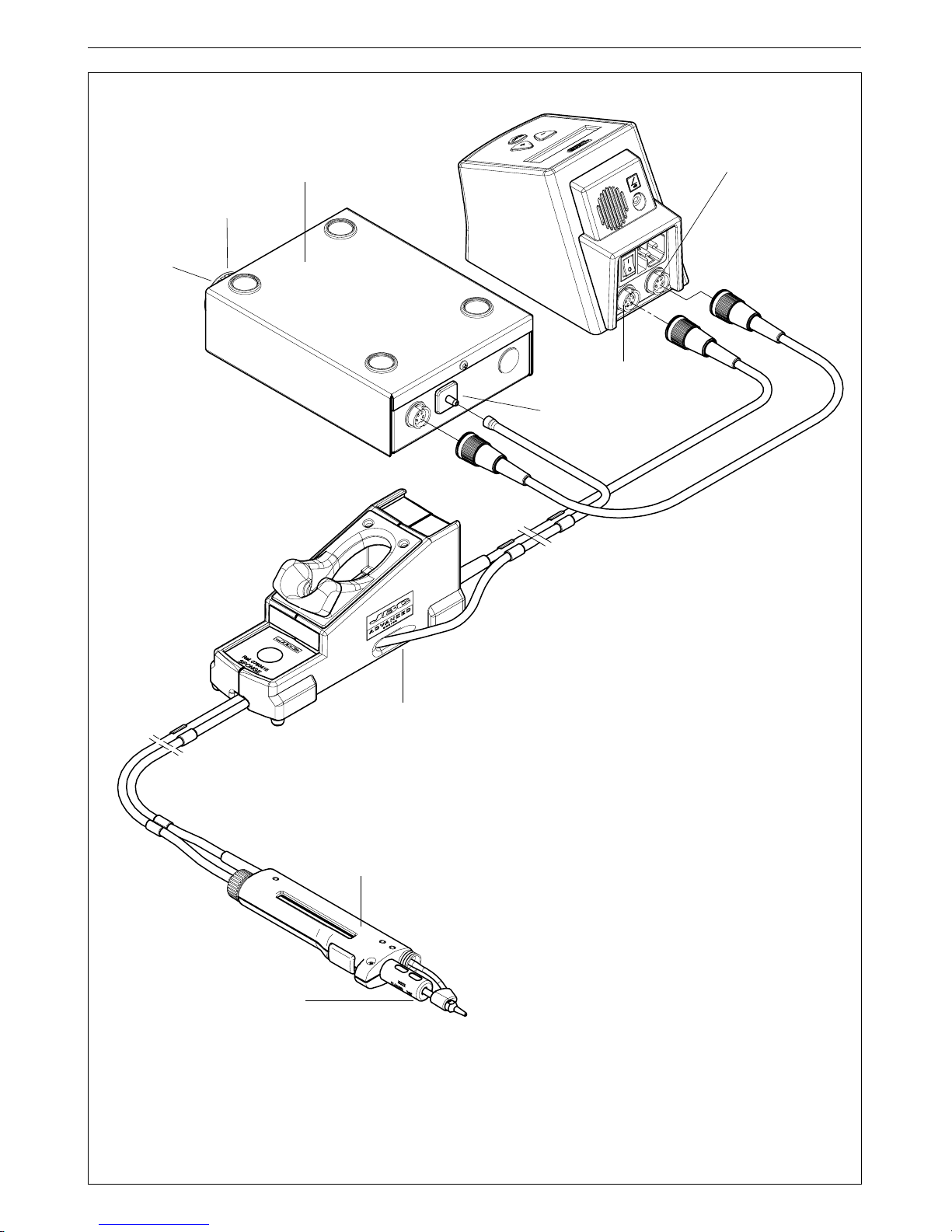
Conector herramienta
Conexión
a red
Conector equipotencial
Conector
bomba desoldadora
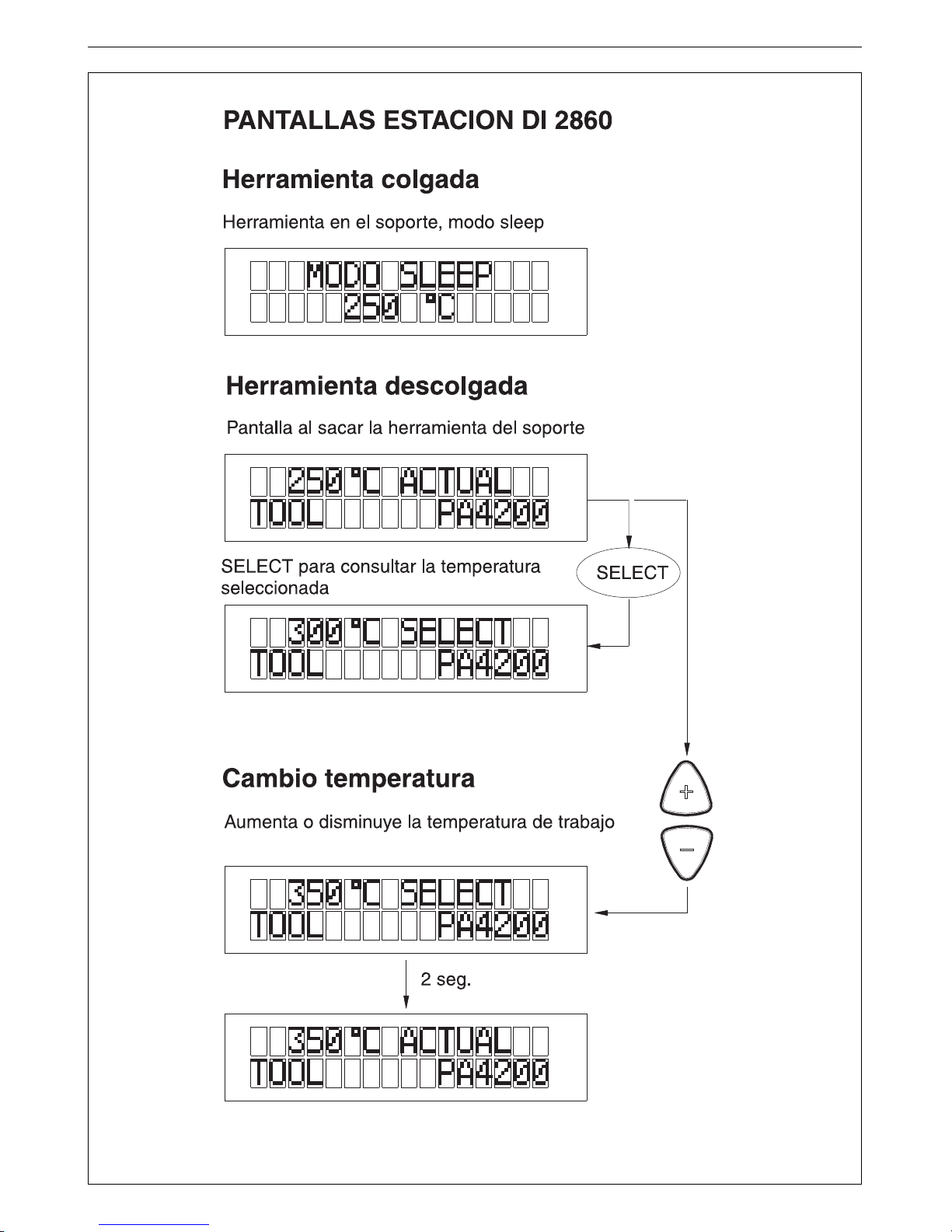
Consulta la
temperatura
seleccionada
Incrementan y
disminuyen la
temperatura
DI 2860 single tool control unit
Page 12
INTRODUCCIÓN AL SISTEMA ADVANCED
DE JBC
Con el exclusivo sistema de calentamiento,
controlado por microprocesador, conseguimos
una excepcional recuperación de la
temperatura que permite trabajar a temperatura
muy baja como nunca se había visto con
anterioridad y mejorando un 40% la eficiencia
de la estación.
Modo hibernación
Es un segundo
Sleep
que hace que la estación
entre en hibernación, es decir, la estación sigue
funcionando pero sin calentar sus
herramientas. Es un estado de mínimo
consumo, pero que cuando detecta que se ha
cogido una herramienta, vuelve a estar
operativa.
Para entrar en modo hibernación previamente
se debe estar en modo
Sleep
. El tiempo de
retraso para entrar en modo hibernación
comienza a contar a partir de entrar en modo
Sleep
.
Los parámetros de la función hibernación se
pueden modificar con el programa de la
estación.
SISTEMA SLEEP
Herramienta en reposo
Una de las cualidades de la serie Advanced,
es que cuando una herramienta se coloca en el
soporte, la temperatura baja automáticamente
hasta la temperatura de reposo (sleep). Esto
es posible, gracias a la rapidez de respuesta
térmica, que permite pasar de la temperatura
de reposo a la de trabajo sin interrupción. Con
lo cual se evita la oxidación del estañado de la
punta y aumenta de 2 a 3 veces la vida de la
punta.
Los parámetros de la función sleep se pueden
modificar con el programa de la estación.
Para beneficiarse del sistema sleep y como
medida de seguridad, es necesario colocar
la herramienta en el soporte cuando no se
utilice.
ESPAÑOL
10
PROGRAMACIÓN
El sistema permite modificar y ajustar la
temperatura entre 90 y 450ºC (190 y 840ºF). Los
valores predeterminados de fábrica son los
siguientes:
- Temperatura mínima: 90ºC
- Temperatura máxima: 400ºC
Para modificar los parámetros de la estación, de
las herramientas y tener acceso a los contadores
se debe mantener pulsada durante 3 segundos
la tecla SELECT. El número de PIN se debe entrar
cuando necesite cambiar un parámetro de la
estación. Número de PIN por defecto: 0105.
En las páginas siguientes tiene los diagramas
de funcionamiento del programa.
La vida de la punta está directamente relacionada
con la temperatura y el tiempo. A más
temperatura durante mayor tiempo, la duración
de la punta se reduce de una forma exponencial.
Por esto es conveniente mantener el soldador
en el soporte, a la temperatura de sleep (200º
C aproximadamente), para aumentar la vida
de la punta.
Mensajes del display
- HIBERNATION: La estación está en modo
hibernación.
- OPEN CIRCUIT. Resistencia soldadora en
circuito abierto. Causas posibles:
Falta introducir correctamente el cartucho en
la herramienta. Cartucho fundido.
- MAXIMUM POWER. Se ha superado la
potencia máxima disponible durante un tiempo
excesivo, por ejemplo soldaduras muy
gruesas y repetidas.
- SHORTCIRCUIT. Cortocircuito en el sistema.
Causas posibles:
Cortocircuito en el lápiz o el cartucho.
- WRONG TOOL. Error de herramienta.
Causas posibles: utilizar una herramienta que
no es compatible con la estación.
- OVERLOAD. Protección para evitar un
sobrecalentamiento de la estación. Se debe
esperar y automáticamente la estación volverá
a estar lista para trabajar.
Causas posibles: excesiva demanda de
potencia.
Si se corrige cualquiera de las causas anteriores,
la estación entrará en funcionamiento
automáticamente, excepto cuando exista un exceso
de aporte de energía (MAXIMUM POWER). En este
caso se debe apagar y volver a conectar la estación.
JBC se reserva el derecho de introducir modificaciones sin
previo aviso
Page 13
11
ESPAÑOL
Vea el diagrama del programa de modificación de los parámetros de la estación en la página 32
Page 14
ESPAÑOL
12
DESOLDADOR DR 5650
La estación DI 2860 permite conectar el
desoldador DR 5650 Ref. 5650000
añadiendo la bomba desoldadora eléctrica
MS 9014 Ref. 9014000 o la bomba
desoldadora de aire comprimido MS 9015
Ref. 9015000.
Para tener el desoldador operativo se
necesita: la unidad de control, el
desoldador, el módulo bomba
desoldadora y el soporte DR 8500.
Estos productos están disponibles como
un accesorio, no se incluyen en la estación.
El desoldador se conecta a la estación de
la siguiente forma:
El cable del desoldador se debe conectar
al soporte desoldador DR 8500 y el tubo de
aspiración a la toma de aspiración de la
bomba desoldadora.
El cable del soporte desoldador se tiene
que conectar al conector de la herramienta
que hay en la parte posterior de la estación
y el cable de la bomba desoldadora en el
conector de la bomba desoldadora.
Desoldador DR 5650
Ref.5650000
Cartucho desoldador
Ref.5650010
Soporte desoldador
DR 8500
Ref.0788500
Conjunto filtro aspiración
Bomba desoldadora eléctrica
MS 9014 Ref.9014000
Bomba desoldadora de aire comprimido
MS 9015 Ref.9015000
Conector herramienta
Conector
bomba desoldadora
Filtros de recambio
Ref.0005966
Toma de aspiración
del desoldador
Page 15

Nous vous remercions de la confiance déposée en JBC à travers l’acquisition de
cette station. Elle est fabriquée dans les plus strictes normes de qualité pour vous
rendre un meilleur service. Avant de mettre l’appareil en marche, nous vous
recommandons de lire attentivement les instructions détaillées ci-après.
Vous venez d’acquérir une unité de contrôle de soudage digitale Advanced DI 2860.
Pour que la station soit complète, vous devez choisir un crayon et/ou une pince à dessouder, les supports
et cartouches respectifs adécuats pour votre travail à réaliser.
FRANÇAIS
13
* Cartouches pour
la pince à
dessouder PA 4200
* Micropince à
dessouder
PA 1200
Réf. 1200000
* Cartouches 1200
* Support pince
à dessouder
PA 8110
Réf. 0748110
Unité de contrôle
DI 2860 230V Réf. 2860200
DI 2860 120V Réf. 2860100
DI 2860 100V Réf. 2860109
* Support pince à
dessouder
PA 8120
Réf. 0748120
* Pince à
dessouder
PA 4200
Réf.4200000
* Ces éléments ne sont pas livrés avec
la station
* Support crayon avec
apport d'étain
AP 8130
Réf. 0788130
* Crayon 2210
Réf. 2210000
* Cartouches 2210
* Cartouches 2245
* Support fer à souder
AD 8245
Réf. 0788245
* Support fer à souder
AD 8210
Réf. 0788210
* Crayon avec apport d'étain
AP 1300
Réf. 1300000
* Cartouches 1300
Filtres de rechange
Réf.0005966
* Crayon 2245
Réf. 2245000
* Fer à dessouder DR 5650
Réf.5650000
* Support du fer à dessouder
DR 8500
Réf.0788500
* Pompe à dessouder électrique
MS 9014 Réf.9014000
* Pompe à dessouder à air comprimé MS 9015 Réf.9015000
Ensemble filtre aspiration
Page 16

FRANÇAIS
14
Unité de contrôle digitale DI 2860
- DI 2860 230V Réf. 2860200
- DI 2860 120V Réf. 2860100
- DI 2860 100V Réf. 2860109
Tous les outils de la gamme Advanced peuvent
être connectés à la unité de côntrole DI 2860 à
condition d'utiliser leur supports respectifs. Le
fer à dessouder DR 5650 peut également être
utilisé à condition d'ajouter la pompe à dessouder
électrique MS 9014 Réf. 9014000 ou la pompe à
dessouder à air comprimé MS 9015 Réf. 9015000.
Composition de la station:
DI 2860 230V Réf. 2860200
- Unité de contrôle DI 2860 230V
-Câble d'alimentation Réf. 0269300
- Manuel d'instructions
DI 2860 120V Réf. 2860100
- Unité de contrôle DI 2860 120V
-Câble d'alimentation Réf. 0269320
- Manuel d'instructions
DI 2860 100V Réf. 2860109
- Unité de contrôle DI 2860 100V
-Câble d'alimentation Réf. 0269320
- Manuel d'instructions
Kit DI 2860 -2245 230V Réf.2860230
- Unité de contrôle DI 2860 230V Réf. 2860200
- Crayon 2245 Réf. 2245000
- Support AD 8245 Réf. 0788245
- Cartouche 2245-003 Réf. 2245003
Kit DI 2860 -2210 230V Réf.2860231
- Unité de contrôle DI 2860 230V Réf. 2860200
- Crayon 2210 Réf. 2210000
- Support AD 8210 Réf. 0788210
- Cartouche 2210-001 Réf. 2210001
Il existe d’autres kits de cette station. Consultez
votre fournisseur.
Données techniques
-Sélection de la température entre 90 et 450°C
ou 190 et 840°F (±5%).
- Puissance: 75W.
- Transformateur de sécurité, séparateur du
secteur et double isolement, avec fusible
intégré pour la protection de température.
- Unité de contrôle DI 2860 230V Réf. 2860200
Entrée: 230V 50Hz. Sortie: 24V.
- Unité de contrôle DI 2860 120V Réf. 2860100
Entrée: 120V 60Hz. Sortie: 24V.
- Unité de contrôle DI 2860 100V Réf. 2860109
Entrée: 100V 60Hz. Sortie: 24V.
- Poids total de l'unité: 2,5Kg.
-Boîtier antistatique "skin effect".
Résistance typique superficielle: 105-10
11
Ohms/carré.
- Conforme aux normes CE portant sur la
sécurité électrique, la compatibilité
électromagnétique et la protection
antistatique.
- Conforme aux norme RoHS.
- La prise équipotentielle et la cartouche sont en
connexion directe avec la prise de terre
secteur pour la protection antistatique (ESD).
Ce produit ne doit pas être jeté à la
poubelle.
RECOMMANDATIONS D’UTILISATION
Pour souder
- De préférence choisir une température
inférieure à 350°C. L’excès de température
réduit la vie de la panne.
- La panne doit être bien étamée pour bien
conduire la chaleur.
Mesures de sécurité
- Placez l’outil sur son support afin de le
laisser refroidir avant de le ranger.
Page 17

Connecteur
outil
Connection
au réseaux
Connecteur équipotentiel
Connecteur
pompe à dessouder
Consulte la
température
selectionnée
Augmentent et
diminuent la
température
DI 2860 single tool control unit
FRANÇAIS
15
Page 18

FRANÇAIS
16
INTRODUCTION AU SYSTÈME ADVANCED
DE JBC
Avec le système de chauffe exclusif, contrôlé
par microprocesseur, nous assurons une
récupération de température ultra-rapide, qui
permet de travailler à très basse température,
comme cela n'avait jamais été vu auparavant.
Et améliorant de 40% l'efficacité de la station.
Mode hibernation
Il s'agit d'un second
Sleep
qui fait que la station
entre en hibernation, c'est à dire que la station
fonctionne mais sans chauffer les outils. C'est un
état de consommation minimum mais qui devient
à nouveau opérationnel dès qu'il détecte qu'un
outil a été pris en main.
Pour entrer en mode hibernation il faut au paravent
être en mode
Sleep
. Le temps de retard pour
entrer en mode hibernation commence à partir
de l'entrée en mode
Sleep
.
Les paramètres de la fonction hibernation
peuvent être modifiés avec le programme de
la station.
SYSTÈME SLEEP
L'outil au repos
La fonction "sleep" constitue une des principales
qualités de la série Advanced: lorsque l'outil
repose sur son support, la température descend
automatiquement à la température de repos. Ceci
est possible grâce à la rapidité de son temps de
réponse thermique, qui permet de passer de la
température de repos à la température de travail
quasi-instantanément. Ceci évite donc l'oxidation
de l'étamage de la pointe et augmente 2 à 3 fois
la durée de vie de la pointe.
Les paramètres de la fonction sleep peuvent
être modifiés avec le programme de la station.
Pour bénéficier du système sleep, et par
mesure de sécurité il est indispensable de
remettre l'outil sur le support lorsqu'il n'est
pas utilisé.
La vie d’une panne est directement liée à la
température et au temps. À davantage de
température pendant un plus long laps de
temps, la durée de la vie de la panne se trouve
réduite de manière exponentielle.
Pour cette raison, il est nécessaire de maintenir
le fer à souder sur le support, à température
de sleep (200ºC approximativement), afin
d’augmenter la vie de la panne.
PROGRAMMATION
Le système permet de modifier et ajuster la
température entre 90 et 450ºC (190 et 840ºF).
Les valeurs de travail prédeterminées sont les
suivantes:
- Température minimum: 90ºC
- Température maximum: 400ºC
Pour modifier les paramètres des outils, de la
station et avoir accès aux compteurs vous devez
maintenir la touche SELECT appuyée pendant 3
secondes. Le code PIN doit être entré lorsque
vous avez besoin de changer les paramètres de
la station. Code PIN par défaut: 0105.
Sur les pages suivantes vous avez les
diagrammes de fonctionnement du programme.
JBC se réserve le droit d'apporter des modifications
techniques à ses appareils sans préavis
Messages du display
- HIBERNATION. La station est en mode
hibernation.
- OPEN CIRCUIT. Resistance de soudage en
circuit ouvert. Causes possibles:
La cartouche n'est pas bien fixée sur l'outil.
Cartouche hors service.
- MAXIMUM POWER. La puissance maximale
disponible a été dépassée pendant trop
longtemps. Par exemple des soudures ou
dessoudures très épaisses et répétées.
- SHORTCIRCUIT. Court-circuit dans le
système.
Causes possibles:
Court-circuit dans la fer ou la cartouche.
- WRONG TOOL. Erreur d'outil.
Causes possibles: utilisation d'un outil non
compatible avec la station.
- OVERLOAD. Protection pour éviter
d’endommager la station par une surchauffe.
Il faut attendre et automatiquement la station
sera à nouveau prête pour travailler.
Causes possibles: demande de puissance
excessive.
Si l'une des causes citées ci-dessus est corrigée
la station se mettra automatiquement en
fonctionnement, sauf s'il y a un apport excessif
d'énergie (MAXIMUM POWER). Dans ce cas il
faut etteindre et reconnecter la station.
Page 19

FRANÇAIS
17
Voyez le diagramme du programme de modification des paramètres de la station en page 32
Page 20

FRANÇAIS
18
FER À DESSSOUDER DR 5650
La station DI 2860 permet de connecter
le fer à dessouder DR 5650 Réf. 5650000
à condition d'ajouter la pompe à dessouder
électrique MS 9014 Réf. 9014000 ou la
pompe à dessouder à air comprimé MS
9015 Réf. 9015000.
Pour avoir un fer à dessouder opérationnel,
vous avez besoin de l’unité de contrôle,
d’un fer à dessouder, le module pompe à
dessoder et le support DR 8500.
Ces produits sont disponibles en tant
qu’accessoires et ne sont pas livrés avec
la station.
Le fer à dessouder se connecte à la station
de la façon suivante:
Le câble du fer à dessouder doit être
connecté au support dessoudeur DR8500
et le tube d’aspiration à la prise d'aspiration
de la pompe à dessouder.
Le câble du support dessouder doit être
connecté au connecteur pour l'outil placé à
l'arrière de la station et le câble de la
pompe à dessouder au connecteur pour
la pompe à dessouder.
Fer à dessouder DR 5650
Réf.5650000
Élément chauffant
Réf.5650010
Support du fer à dessouder
DR 8500
Réf.0788500
Ensemble filtre aspiration
Pompe à dessouder électrique
MS 9014 Réf.9014000
Pompe à dessouder à air comprimé
MS 9015 Réf.9015000
Connecteurs outil
Connecteur
pompe à dessouder
Filtres de rechange
Réf.0005966
Prise d'aspiration
du fer à dessouder
Page 21

DEUTSCH
19
Wir danken Ihnen für das JBC mit dem Kauf dieser Station erwiesene Vertrauen. Bei ihrer
Fertigung wurden die strengsten Qualitätsmaßstäbe zugrunde gelegt, so dass Sie
optimale Lötergebnisse erwarten dürfen. Vor Inbetriebnahme des Geräts lesen Sie bitte
die vorliegende Betriebsanleitung aufmerksam durch.
Sie haben eine digitale Lötsteuereinheit Advanced DI 2860 erworben.
Damit Sie mit der Lötstation arbeiten können, müssen Sie Werkzeug, Ständer und Kartuschen
auswählen, die für die zu verrichtende Arbeit geeignet sind.
* Kartuschen für
die Entlötpinzette
PA 4200
* Mikroentlötpinzette
PA 1200
Ref. 1200000
* Kartuschen 1200
* Entlötpinzettenständer
PA 8110
Ref. 0748110
Steuereinheit
DI 2860 230 V Ref. 2860200
DI 2860 120 V Ref. 2860100
DI 2860 100 V Ref. 2860109
* Entlötpinzettenständer
PA 8120
Ref. 0748120
* Entlötpinzette
PA 4200
Ref. 4200000
* Diese Elemente werden nicht mit der
Station geliefert
* Zinnzufuhrlötkolbenständer
AP 8130
Ref. 0788130
* Handstück 2210
Ref. 2210000
* Kartuschen 2210
* Kartuschen 2245
* Lötkolbenständer
AD 8245
Ref. 0788245
* Lötkolbenständer
AD 8210
Ref. 0788210
* Lötkolben mit
Zinnzufuhr AP 1300
Ref. 1300000
* Kartuschen 1300
* Entlötkolben DR 5650
Ref.5650000
Ersatzfilter
Ref.0005966
* Entlötkolbenständer
DR 8500
Ref.0788500
* Elektrische Entlötpumpe MS 9014 Ref.9014000
* Druckluftpumpe zum Entlöten MS 9015 Ref.9015000
* Handstück 2245
Ref. 2245000
Saugfiltereinheit
Page 22

DEUTSCH
20
Digitale Steuereinheit DI 2860
- DI 2860 230 V Ref. 2860200
- DI 2860 120 V Ref. 2860100
- DI 2860 100 V Ref. 2860109
An die Steuereinheit DI 2860 können alle
Werkzeuge unseres Advanced-Sortiments
angeschlossen werden, sofern immer der
entsprechende Ständer benutzt wird. Sogar der
Entlötkolben DR 5650, wenn die elektrische
Entlötpumpe MS 9014 Ref. 9014000 oder die
Druckluftpumpe zum Entlöten MS 9015 Ref.
9015000 hinzugefügt wird
..
..
.
Technische Daten
- Temperaturwahl zwischen 90 und 450° C oder
190 und 840° F (±5%).
- Leistung: 75 W
- Netzgetrennter Sicherheitstransformator mit
doppelter Isolierung und integrierter
Brandschutzsicherung.
- Steuereinheit DI 2860 230 V Ref. 2860200
Eingangsspannung: 230 V 50 Hz
Ausgangsspannung: 24 V
- Steuereinheit DI 2860 120 V Ref. 2860100
Eingangsspannung: 120 V 60 Hz
Ausgangsspannung: 24 V
- Steuereinheit DI 2860 100 V Ref. 2860109
Eingangsspannung: 100 V 60 Hz
Ausgangsspannung: 24 V
- Gewicht der kompletten Anlage: 2,5 kg
- Astatisches Gehäuse.
Typischer Oberflächenwiderstand:
105-1011 Ohm/Quadrat.
- Erfüllt die EG-Sicherheitsvorschriften über
elektrische Sicherheit, elektromagnetische
Kompatibilität und antistatischen Schutz.
- Erfüllt die RoHS-Vorschriften.
- Die Equipotentialausgleichsbuchse und die
Lötspitze sind zum Schutz gegen
elektrostatische Entladungen mit der Erdung
des Netzsteckers verbunden.
Dieses Produkt darf nicht mit dem
Hausmüll entsorgt werden.
Aufbau der Station:
DI 2860 230 V Ref. 2860200
- Steuereinheit DI 2860 230 V
- Kaltgerätestecker Ref. 0269300
- Bedienungsanleitung
DI 2860 120 V Ref. 2860100
- Steuereinheit DI 2860 120 V
- Kaltgerätestecker Ref. 0269320
- Bedienungsanleitung
DI 2860 100 V Ref. 2860109
- Steuereinheit DI 2860 100 V
- Kaltgerätestecker Ref. 0269320
- Bedienungsanleitung
Kit DI 2860 -2245 230 V Ref.2860230
- Steuereinheit DI 2860 230 V Ref. 2860200
- Handstück 2245 Ref. 2245000
-Lötkolbenständer AD 8245 Ref. 0788245
- Kartusche 2245-003 Ref. 2245003
Kit DI 2860 -2210 230 V Ref.2860231
- Steuereinheit DI 2860 230 V Ref. 2860200
- Handstück 2210 Ref. 2210000
-Lötkolbenständer AD 8210 Ref. 0788210
- Kartusche 2210-001 Ref. 2210001
Es sind noch weitere Kits dieser Station lieferbar.
Erkundigen Sie sich bei Ihrem Händler.
EMPFEHLUNGEN FÜR DEN GEBRAUCH
Zum Löten und Entlöten
-Möglichst immer mit Temperaturen unter 350°
C arbeiten. Zu hohe Temperaturen verkürzen
die Standzeit der Lötspitze.
- Damit die Spitze gut die Wärme leitet, muss
sie gut verzinnt sein.
Sicherheitsvorkehrungen
- Nach dem Gebrauch das Werkzeug in
seinem Ständer abstellen und abkühlen
lassen, bevor es aufbewahrt wird.
Page 23

DEUTSCH
21
Werkzeuganschluss
Netzanschluss
Equipotentialausgleichsbuchse
Anschluss Entlötpumpe
Abfrage der
ausgewählten
Temperatur
Erhöhen und
senken die
Temperatur
DI 2860 single tool control unit
Page 24

DEUTSCH
22
PROGRAMMIERUNG
Das System ermöglicht die Temperatur zwischen
90 und 450º C (190 und 840º F) zu verändern und
einzustellen. Werksseitig werden die folgenden
Werte eingestellt:
SLEEP-SYSTEM
Werkzeuge in Standby-Funktion
Eine der Stärken der Advanced-Serie liegt darin,
dass die Temperatur automatisch auf die StandbyTemperatur abgesenkt wird, wenn ein Werkzeug im
Ständer abgestellt wird. Das direkte thermische
Ansprechen macht es möglich, ohne Unterbrechung
von der Standby-Temperatur zur Arbeitstemperatur
zu wechseln. Dadurch wird die Oxidierung der Spitze
vermieden und die Lebensdauer der Spitze um das
2- bis 3 fache verlängert.
Die Parameter der Sleep-Funktion lassen sich
mit dem Programm der Station ändern.
Um das Sleep-System auszunutzen, ist es
erforderlich, das Werkzeug bei
Nichtbenutzung im Ständer abzulegen.
EINFÜHRUNG IN DAS ADVANCED-SYSTEM
VON JBC
Mit dem exklusiven, von einem Mikroprozessor
gesteuerten Aufheizsystem erreichen wir eine
außerordentliche Aufheizzeit, die es ermöglicht,
bei bislang nicht für möglich gehaltener, sehr
geringer Temperatur zu arbeiten und die
Effizienz der Station um 40% zu verbessern.
Betriebsart Hibernation
Ist eine zweite Stufe der Sleep-Funktion, die dafür
sorgt, dass die Station in eine Art Winterschlaf
fällt, d.h. die Station bleibt weiterhin in Betrieb,
heizt allerdings nicht die Werkzeuge auf. Dies ist
ein Zustand mit äußerst geringem Verbrauch,
aber sobald das Werkzeug in die Hand
genommen wird, ist es erneut einsatzbereit.
Die Betriebsart
Hibernation
ist nur aus der
Betriebsart
Sleep
heraus zu erreichen. Das
Verzögerungsintervall, bevor in die Betriebsart
Hibernation
umgeschaltet wird, beginnt dann,
wenn die Betriebsart
Sleep
anfängt.
Die Parameter der Betriebsart
Hibernation
lassen
sich mit dem Programm der Station ändern
..
..
.
Die Lebensdauer der Spitze hängt direkt von
der Temperatur und der Zeit ab. Bei höherer
Temperatur über längere Zeiträume vermindert
sich die Standzeit der Spitze in exponentieller
Weise.
Daher ist es sinnvoll, den Lötkolben im
Ständer zu lassen und eine StandbyTemperatur von etwa 200º C zu wählen, um
die Standzeit der Spitze zu verlängern.
Anzeigen auf dem Display
- HIBERNATION: Die Station befindet sich in der
Betriebsart Hibernation.
- OPEN CIRCUIT. Offener Kreis in Lötresistenz.
Mögliche Ursachen:
Die Kartusche muss ordnungsgemäß in das
Werkzeug eingesetzt werden.
Durchgebrannte Kartusche.
- MAXIMUM POWER. Über einen längeren
Zeitraum wurde die maximale Leistung
überschritten, z.B. durch das wiederholte
Löten oder Entlöten sehr großer Lötstellen usw.
- SHORTCIRCUIT. Kurzschluss im System.
Mögliche Ursachen:
Kurzschluss am Handstück oder der Kartusche.
- WRONG TOOL. Werkzeugfehler.
Mögliche Ursachen: es wird ein Werkzeug
benutzt, das nicht mit der Station kompatibel ist.
- OVERLOAD. Schutzvorrichtung, um die
Schädigung des Stationskreislaufs durch
Überhitzung zu verhindern. Man muss warten,
bis die Temperatur abgesunken ist und dann
ist die Station automatisch wieder betriebsbereit.
Mögliche Ursachen: Ausführung von sehr
dicken und wiederholten Lötungen.
Wenn irgendeine der vorher genannten Ursachen
behoben worden ist, setzt sich die Station wieder
automatisch in Betrieb, außer, wenn ein
Spannungsüberschuss entstanden ist (MAXIMUM
POWER). In diesem Fall ist die Station aus- und
danach wieder einzuschalten.
JBC behält sich das Recht vor, technische oder konstruktive
Änderungen ohne vorherige Ankündigung vorzunehmen
- Minimaltemperatur: 90ºC
- Maximaltemperatur: 400ºC
Um die werksseitigen Parameter zu ändern und
Zugriff auf die Zähler zu erhalten, muss man das
entsprechende Werkzeug anheben und die Taste
SELECT 3 Sekunden lang gedrückt halten. Die
PIN-Nummer muss eingegeben werden, wenn ein
Stationsparameter geändert werden soll.
Voreingestellte PIN-Nummer: 0105.
Auf den folgenden Seiten sehen Sie die
Ablaufdiagramme des Programms.
Page 25

DEUTSCH
23
Sehen Sie auf foldender Seite 32 die Programmdiagramme der Veränderung der Parameters der
Steuereinheit
Page 26

DEUTSCH
24
ENTLÖTKOLBEN DR 5650
Wenn man zusätzlich die elektrische
Entlötpumpe MS 9014 Ref. 9014000 oder
die Druckluftpumpe zum Entlöten MS 9015
Ref. 9015000 anschließt, kann man den
Entlötkolben DR 5650 Ref. 5650000 an die
Station DI 2860 anschließen.
Damit der Entlötkolben einsatzbereit ist,
benötigt man: die Steuereinheit, den
Entlötkolben, das Modul Entlötpumpe und
den Ständer DR 8500.
Diese Artikel sind zusätzlich erhältlich und
sind nicht im Lieferumfang der Station
enthalten.
Der Entlötkolben wird folgendermaßen an
die Station angeschlossen:
Das Anschlusskabel des Entlötkolbens
wird in die Buchse des Entlötkolbenständers
DR 8500 eingesteckt und der
Vakuumschlauch in den Sauganschluss
der Entlötpumpe.
Das Anschlusskabel des
Entlötkolbenständers muss an den
Werkzeuganschluss an der Rückseite der
Station und das Kabel der Entlötpumpe an
den Anschluss für die Entlötpumpe
angeschlossen werden.
Entlötkolben DR 5650
Ref.5650000
Kartusche
Ref.5650010
Entlötkolbenständer
DR 8500
Ref.0788500
Saugfiltereinheit
Elektrische Entlötpumpe
MS 9014 Ref.9014000
Druckluftpumpe zum Entlöten
MS 9015 Ref.9015000
Werkzeuganschlüss
Anschluss Entlötpumpe
Ersatzfilter
Ref.0005966
Unterdruckanschluss
des Entlötkolbens
Page 27

ITALIANO
25
Lei ha acquistato una unità di controllo saldante digitale Advanced DI 2860.
Per avere la stazione saldante completa si deve scegliere l'utensile, il supporto e le cartucce
adeguate al lavoro da realizzare.
La ringraziamo per la fiducia che ha riposto nella JBC con l’acquisto di questa stazione.
Essa è stata fabbricata secondo le più rigide norme di qualità, per offrirLe il servizio
migliore. Prima di accendere l’apparecchio, Le consigliamo di leggere attentamente le
istruzioni che seguono.
* Cartucce per la
pinza dissaldante
PA 4200
* Micro pinza dissaldante
PA 1200
Rif. 1200000
* Cartucce 1200
* Supporto
pinza
dissaldante
PA 8110
Rif. 0748110
Unità di controllo
DI 2860 230V Rif. 2860200
DI 2860 120V Rif. 2860100
DI 2860 100V Rif. 2860110
* Supporto pinza
dissaldante
PA 8120
Rif. 0748120
* Pinza
dissaldante
PA 4200
Rif. 4200000
* Questi elementi non sono in dotazione
con la unità di controllo
* Supporto saldatore
con apporto di stagno
AP 8130
Rif. 0788130
* Stilo 2210
Rif. 2210000
* Cartucce 2210
* Cartucce 2245
* Supporto saldatore
AD 8245
Rif. 0788245
* Supporto saldatore
AD 8210
Rif. 0788210
* Saldatore con apporto di
stagno AP 1300
Rif. 1300000
* Cartucce 1300
* Dissaldatore DR 5650
Rif.5650000
Filtri di ricambio
Rif.0005966
* Supporto dissaldatore
DR 8500
Rif.0788500
* Pompa dissaldante elettrica MS 9014
Rif.9014000
* Pompa dissaldante ad aria compressa MS 9015
Rif.9015000
* Stilo 2245
Rif. 2245000
Gruppo filtro aspirazione
Page 28

ITALIANO
26
Unità di controllo digitale DI 2860
- DI 2860 230V Rif. 2860200
- DI 2860 120V Rif. 2860100
- DI 2860 100V Rif. 2860109
Si possono connettere alla stazione tutti gli utensili
della gamma Advanced usando sempre il
supporto corrispondente, incluso il dissaldatore
DR 5650 aggiungendo la pompa dissaldante
elettrica MS 9014 Rif. 9014000 o la pompa
dissaldante ad aria compressa MS 9015
Rif.9015000.
Composizione della estazione:
DI 2860 230V Rif. 2860200
- Unità di controllo DI 2860 230V
- Cavo di connessione a rete Rif. 0269300
- Manuali d'istruzione
DI 2860 120V Rif. 2860100
- Unità di controllo DI 2860 120V
- Cavo di connessione a rete Rif. 0269320
- Manuali d'istruzione
DI 2860 100V Rif. 2860109
- Unità di controllo DI 2860 100V
- Cavo di connessione a rete Rif. 0269320
- Manuali d'istruzione
Kit DI 2860 -2245 230V Rif.2860230
- Unità di controllo DI 2860 230V Rif. 2860200
- Stilo 2245 Rif. 2245000
- Supporto AD 8245 Rif. 0788245
- Cartuccia 2245-003 Rif. 2245003
Kit DI 2860 -2210 230V Rif.2860231
- Unità di controllo DI 2860 230V Rif. 2860200
- Stilo 2210 Rif. 2210000
- Supporto AD 8210 Rif. 0788210
- Cartuccia 2210-001 Rif. 2210001
Esistono vari kit di questa stazione. Chiedete al
Vs. fornitore.
Dati tecnici
- Selezione della temperatura tra 90 e 450°C o
190 e 840°F (±5%).
- Potenza: 75W
- Trasformatore di sicurezza, separatore di
rete a doppio isolamento, con fusibile
integrato di protezione della temperatura.
- Unità di controllo DI 2860 230V Rif. 2860200
Entrata: 230V 50Hz Uscita: 24V
- Unità di controllo DI 2860 120V Rif. 2860100
Entrata: 120V 60Hz Uscita: 24V
- Unità di controllo DI 2860 100V Rif. 2860109
Entrata: 100V 60Hz Uscita: 24V
- Peso unità: 2,5 kg
- Cassa antistatica.
Resistenza tipica superficiale: 105-1011 Ohms/
quadro.
- Compie la normativa CE sulla sicurezza
elettrica, compatibilitá elettromagnetica e
protezione antistatica.
- Compie la normativa RoHS.
- Il connettore equipotenziale e la punta del
saldatore sono collegati direttamente alla presa
di terra della spina per protezione ESD.
Questo prodotto non deve seguire il
normale percorso di smaltimento dei rifiuti.
CONSIGLI PER L’USO
Per saldare e dissaldare
- Selezionare preferibilmente una
temperatura inferiore a 350°C. Una
temperatura eccessiva riduce la vita della
punta.
- La punta deve essere ben stagnata per
condurre bene il calore.
Precauzioni di sicurezza
- Collocare l’utensile nel suo supporto dopo l’
uso e lasciarlo raffreddare prima di
immagazzinarlo.
Page 29

Connessione utensile
Connessione
a rete
Connettore
equipotenziale
Connettore
pompa dissaldante
Consulta la
temperatura
selezionata
Aumenta e
disminuisce la
temperatura
DI 2860 single tool control unit
ITALIANO
27
Page 30

ITALIANO
28
PROGRAMMAZIONE
Il sistema permette di modificare e regolare la
temperatura tra 90 e 450ºC (190 e 840ºF). I valori
predeterminati in fabbrica sono i seguenti:
- Temperatura minima: 90ºC
- Temperatura massima: 400ºC
Per modificare tanto i parametri della stazione
come degli utensili ed avere accesso ai contatori
si deve mantenere premuto durante 3 secondi il
tasto SELECT. Il numero di PIN si deve inserire
quando desidera cambiare un parametro della
stazione. Numero di PIN preimpostato: 0105.
Nelle pagine seguenti sono riportati i diagrammi di
funzionamento del programma.
FUNZIONE SLEEP
Utensile in riposo
Una delle qualità della serie Advanced è
l’abbassamento della temperatura dell'utensile
quando si pone nel supporto, riducendosi fino
alla temperatura di riposo (sleep). Questo fa sí
che grazie alla sua rapidità di risposta termica
passi dalla temperatura di riposo alla temperatura
di lavoro senza interruzione. Il tutto evita
l'ossidazione della parte prestagnata della punta
e aumenta da 2 a 3 volte la vita della punta.
I parametri della funzione sleep si possono
modificare con il programma della stazione.
Per beneficiarsi della funzione sleep e come
misura di sicurezza, è necessario riporre
l'utensile nel supporto quando non si
utilizza.
INTRODUZIONE AL SISTEMA ADVANCED DI
JBC
Con l'esclusivo sistema di riscaldamento,
controllato con un microprocessore, riusciamo
ad ottenere un eccezionale recupero della
temperatura che consente lavorare con
temperatura bassissime, come non si era mai
visto sinora migliorando del 40% l'efficenza della
stazione.
Modo ibernazion
É un secondo
Sleep
che fa in modo che la stazione
entri in ibernazione, ossia, la stazione continua a
funzionare ma senza riscaldare i suoi utensili. É
uno stato di minimo consumo, peró quando viene
rilevato che é stato preso l’utensile, la stazione
ritorna operativa.
Per entrare nel modo ibernazion si deve stare
previamente nel modo
Sleep
. Il tempo di ritardo
per entrare nel modo ibernazion comincia a
contare a partire dall’entrata nel modo
Sleep
.
I parametri della funzione ibernazion si possono
modificare con il programma della stazione.
La durata della punta è direttamente
relazionata alla temperatura e al tempo. Con
una maggiore temperatura durante un tempo
più lungo, la durata della punta si riduce in
forma esponenziale.
Per questo è consigliabile mantenere il
saldatore nel supporto, a una temperatura di
sleep (200º C circa), al fine di aumentare la
durata della punta.
Indicazioni dei display
- HIBERNATION: La stazione si trova nel modo
di ibernazione.
- OPEN CIRCUIT. Resistenza aperta. Cause
possibili: Cartuccia non inserita
correttamente nello strumento.
Cartuccia interrotta.
- MAXIMUM POWER. Che si è superata la
massima potenza disponibile durante un
tempo eccessivo, ad esempio effettuando
saldature o dissaldature molto spesse con
una frequenza molto alta.
- SHORTCIRCUIT. Cortocircuito nel sistema.
Cause possibili:
Cortocircuito nello stilo o nella cartuccia.
- WRONG TOOL. Errore dell'utensile.
Cause posibili: utensile non compatibile con la
stazione.
- OVERLOAD. Protezione per evitare che si
danneggi la stazione per un
sovrariscaldamento. Si deve aspettare e
automaticamente la stazione sará di nuovo
pronta all’uso.
Cause possibili: eccessiva richiesta di
potenza.
Se si corregge qualsiasi delle cause precedenti
la stazione entrerà in funzione automaticamente,
eccetto quando esiste una richiesta eccessiva di
energia (MAXIMUM POWER). In questo caso si
deve spegnere e riaccendere la stazione.
JBC si reserva il diritto d'introdurre variazioni tecniche senza
preavviso
Page 31

ITALIANO
29
Vedasi a pag. 32 il diagramma del programma di modifica dei parametri della stazione
Page 32

ITALIANO
30
DISSALDATORE DR 5650
La stazione DI 2860 permette di connettare
il dissaldatore DR 5650 Rif. 5650000
aggiungendo la pompa dissaldante
elettrica MS 9014 Rif. 9014000 o la pompa
dissaldante ad aria compressa MS 9015
Rif.9015000.
Per avere il dissaldatore operativo è
necessario: l'unità di controllo, il
dissaldatore, il modulo pompa dissaldante
ed il supporto DR 8500.
Questi elementi non sono in dotazione con
la stazione.
Il dissaldatore si collega alla stazione nel
seguente modo:
Il cavo del dissaldatore si deve connettere
al supporto dissaldatore DR 8500 ed il
tubo di aspirazione alla presa di aspirazione
della pompa dissaldante.
Il cavo del supporto del dissaldatore si
deve collegare al connettore dell'utensile
presenti nella parte posteriore della
stazione ed il cavo della pompa dissaldante
a suo opposito connettore.
Dissaldatore DR 5650
Rif.5650000
Cartuccia dissaldatore
Rif.5650010
Supporto dissaldatore
DR 8500
Rif.0788500
Gruppo filtro aspirazione
Pompa dissaldante elettrica
MS 9014 Rif.9014000
Pompa dissaldante ad aria compressa
MS 9015 Rif.9015000
Connessione utensile
Connettore
pompa dissaldante
Filtri di ricambio
Rif.0005966
Presa di aspirazione
del dissaldatore
Page 33

Page 34

32
Page 35

33
Page 36

Page 37

ELECTRIC WIRING DIAGRAM
35
Page 38

Page 39

DI 2860 230V
37
Page 40

Page 41

DI 2860 120V
39
Page 42

DI 2860 100V
40
Page 43

WARRANTY ENGLISH
The JBC 2 years warranty, guarantees
this equipment against all manufacturing
defects, covering the replacement of
defective parts and all necessary labour.
Warranty does not cover product wear
due to use or mis-use.
In order for the warranty to be valid,
equipment must be returned, postage
paid, to the dealer where it was
purchased enclosing this, fully filled in,
sheet.
GARANTIA ESPAÑOL
JBC garantiza este aparato durante 2
años, contra todo defecto de fabricación,
cubriendo la reparación con sustitución
de las piezas defectuosas e incluyendo
la mano de obra necesaria.
Quedan excluidas de esta garantía las
averías provocadas por mal uso del
aparato y desgaste por uso.
Es indispensable para acogerse a esta
garantía el envio del aparato al
distribuidor donde se adquirió, a portes
pagados, adjuntando esta hoja
debidamente cumplimentada.
GARANTIE FRANÇAIS
JBC garantit cet appareil 2 ans contre
tout défaut de fabrication. Cela comprend
la réparation, le remplacement des
pièces défectueuses et la main d'oeuvre
nécessaire.
La garantie ne couvre pas l’usure liée à
l’utilisation et à la mauvaise utilisation du
matériel.
Pour bénéficier de cette garantie il est
indispensable d'envoyer l'appareil chez
le distributeur où il a été acquis, en ports
payés, en joignant cette fiche dûment
remplie.
✂
Page 44

0005906-0207
GARANTIE DEUTSCH
Für das vorliegende Gerät übernimmt
JBC eine Garantie von 2 Jahren, für alle
Fabrikationsfehler. Diese Garantie
schliesst die Reparatur bzw. den Ersatz
der defekten Teile sowie die
entsprechenden Arbeitskosten ein.
Ausgeschlossen von dieser
Garantieleistung sind durch
unsachgemässen Gebrauch
hervorgerufene Betriebsstörungen und
normale Gebrauchsabnützungen.
Zur Inanspruchnahme dieser Garantie
muss das Gerät portofrei an den
Vertriebshändler geschickt werden, bei
dem es gekauft wurde. Fügen Sie dieses
vollständig ausgefüllte Blatt bei.
GARANZIA ITALIANO
La JBC garantisce quest'apparato 2
anni contro ogni difetto di fabbricazione,
e copre la riparazione e la sostituzione
dei pezzi difettosi, includendo la mano
d'opera necessaria.
Sono escluse da questa garanzia le
avarie provocate da cattivo uso
dell'apparato e logorio da utilizzo.
Per usufruire di questa garanzia, è
indispensabile inviare, in porto franco,
l'apparato al distributore presso il quale
è stato acquistato, unitamente a questo
foglio debitamente compilato.
DATE OF PURCHASE
FECHA DE COMPRA
DATE D'ACHAT
KAUFDATUM
DATA DI ACQUISTO
STAMP OF DEALER
SELLO DEL DISTRIBUIDOR
CACHET DU DISTRIBUTEUR
STEMPEL DES HÄNDLERS
TIMBRO DEL DISTRIBUTORE
SERIAL Nº
✂
MANUFACTURED BY
JBC Industrias, S.A.
Ramón y Cajal, 3 - 08750 MOLINS DE REI
BARCELONA - SPAIN
Tel.: +34 93 325 32 00 - Fax: +34 93 680 49 70
http://www.jbctools.com e-mail:info@jbctools.com
 Loading...