

Page 1

Deutsch 42
Español 22
Premium Rework Station
with Pneumatic Pump
Ref. DDVE-B
English 2
Page
www.jbctools.com
Page 2

Packing List
The following items should be included:
Stand Cable ................ 2 units
Re f. 0 0112 83
Stand ................ 1 unit
Ref. AD-SD
Sponge ............................ 1 unit
Ref. S0354
Metal Brush .................... 1 unit
Ref. CL6217
Pneumatic Desoldering
Module ............................. 1 unit
Ref. MVE-A
Tip Cleaner ..................... 1 unit
Ref. CL6166
Module Cable ................ 1 unit
Re f. 0 014 874
DDE Control Unit .......... 1 unit
Ref. DDE-1B (120V)
DDE-2B (230V)
DDE-9B (100V)
Union Flanges ............... 1 unit
Re f. 0 0113 56
Desoldering
Iron .................... 1 unit
Ref. DR560-A
Stand ................ 1 unit
Ref. DR-SD
Power cord .................... 1 unit
Ref. 0010569 (230V)
0013671 (100/120V)
General Purpose
Handle .............. 1 unit
Ref. T245-A
2
Page 3
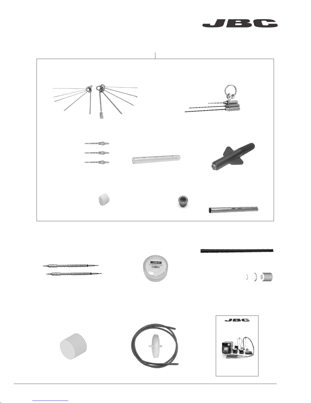
Manual ............................. 1 unit
Ref. 0017356
Premium Rework Station
with Pneumatic Pump
Ref. DDVE-B
Suction Filter ................. 1 unit
Ref. 0821830
Cotton Filter .................... 1 unit
Ref. 0781046
It contains 10 filters
DR560 Accessories
Re f. 0 010211
Internal gasket .......... 1 unit
Ref. 0019208
It contains 2 gaskets
Filter Box .................... 1 unit
Ref. 0780840
It contains 10 filters
Spanner ...................... 1 unit
Ref. 0780550
Glass solder
collector ...................... 1 unit
Ref. 0812620
Metal solder
collector ...................... 1 unit
Ref. 0812630
Tips ............................. 3 units
Ref. C560005
Ref. C560013
Ref. C560004
Cleaning stick ................. 1 unit
Ref. 0786640
Cartridges .................... 2 units
Ref. C245903 (x1)
C245906 (x1)
Filter Box .......................... 1 unit
Ref. 0005966
It contains 50 filters
Venturi Filter ................... 1 unit
Ref. 0008446
Tip cleaning set ................................... 1 unit
Ref. 0965970
Long Tip Cleaning set ....................... 1 unit
Ref. 0965760
www.jbctools.com
3
www.jbctools.com
Page 4
Stand
Ref. DR-SD
Stand Cable
Re f. 0 0112 83
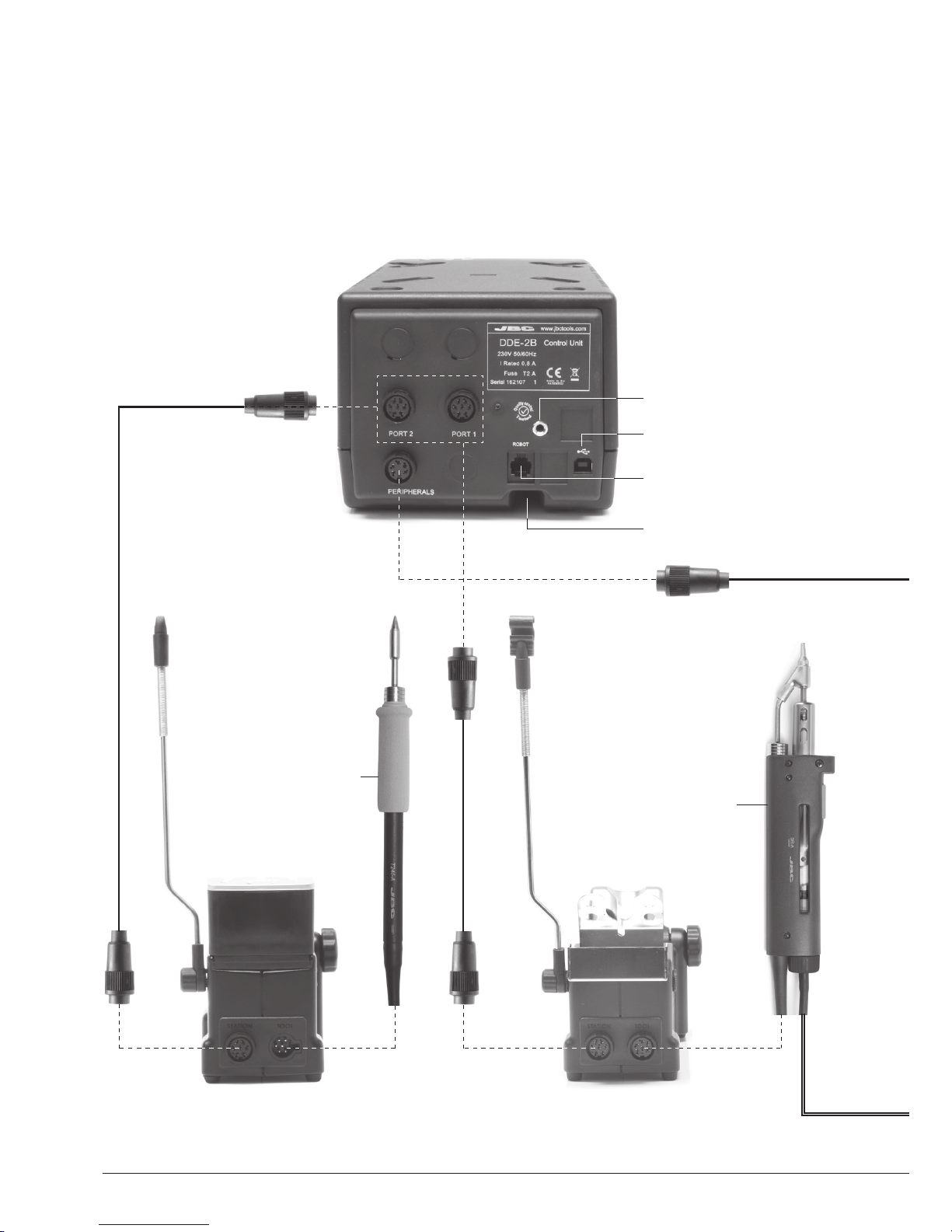
Features
Work simultaneously with up to 2 tools and join each station port with 1 module + 1 pedal (Peripherals).
Stand
Ref. AD-SD
RJ12 connector for Robot
USB-B connector
Equipotential connection
Power Socket
Desoldering Iron
Ref. DR560-A
General
Purpose
Handle
Ref. T245-A
4
Page 5
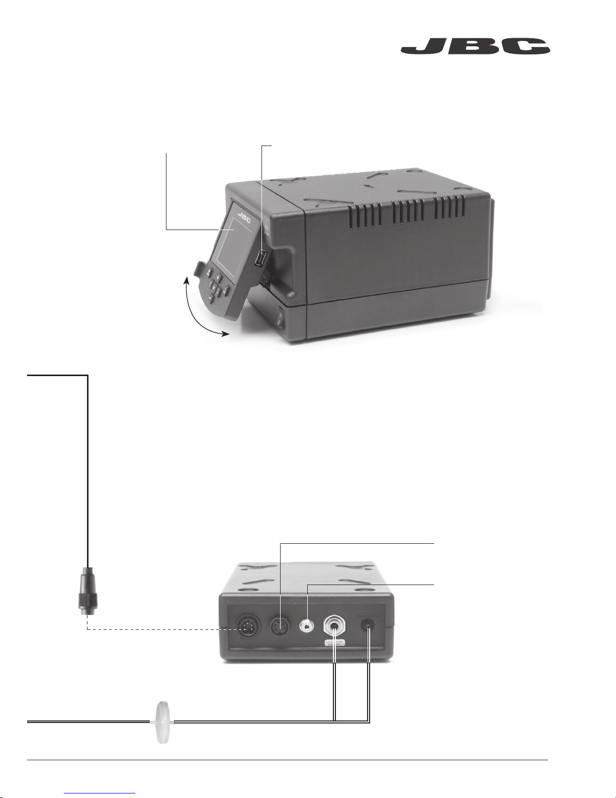
Suction Filter
Ref. 0821830
Module Cable
Re f. 0 014 874
USB-A connector2,8” Color TFT screen
Tilt the display
for easy reading
Air pressure (4-6 bar)
Pneumatic Desoldering Module
Ref. MVE-A
To another peripheral
To Pedal
Ref. P-005
www.jbctools.com
5
Page 6
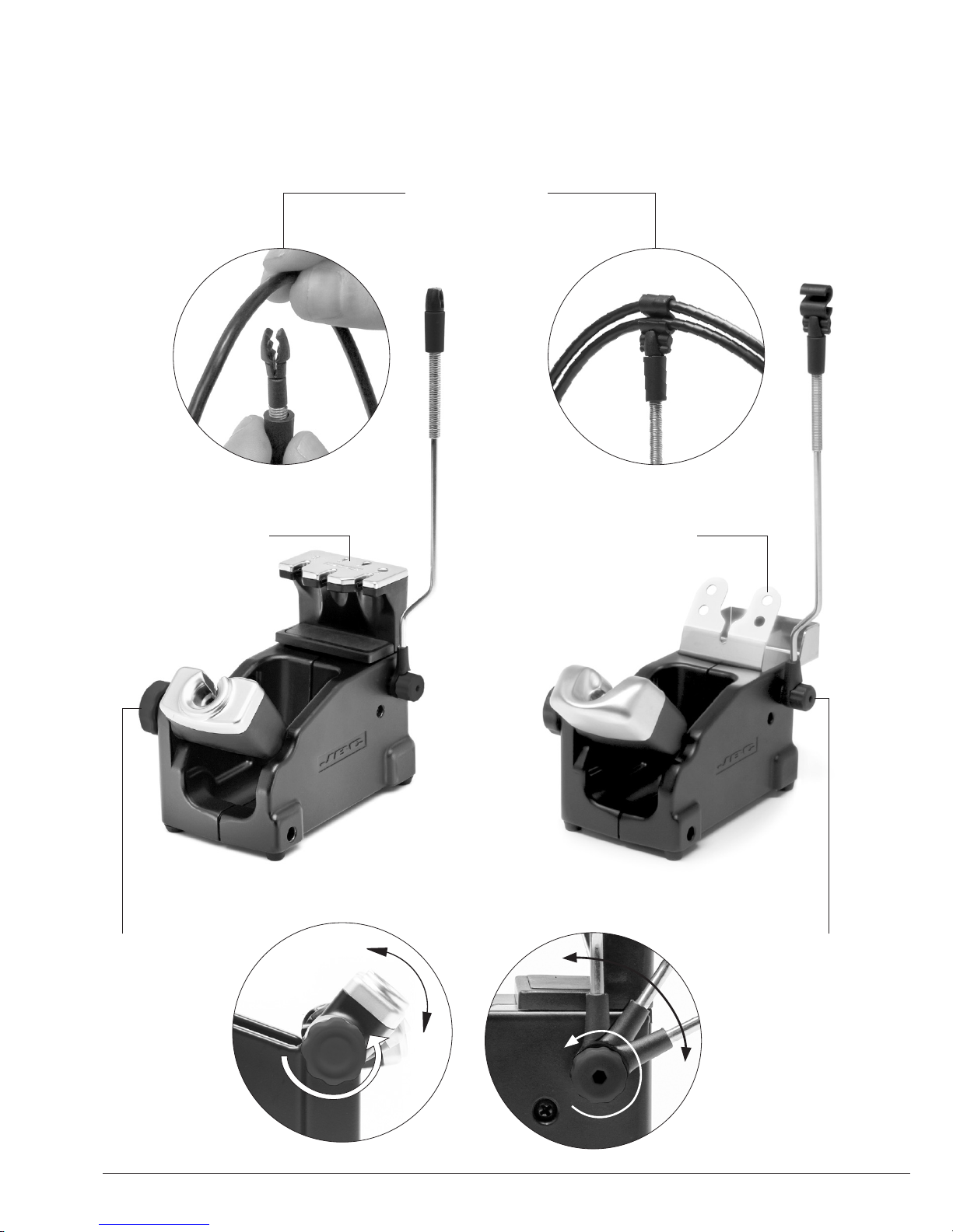
Quick tip changer
Permits switching
cartridges without
interrupting your work.
Adjustable
tool holder
Suits your work
position.
Adjustable
cable collector
Adjustable Stands
Stand
Ref. DR-SD
Quick tip changer
Holding tip system
for easy change.
Cable collector
Keeps working area free of cable.
Stand
Ref. AD-SD
6
Page 7
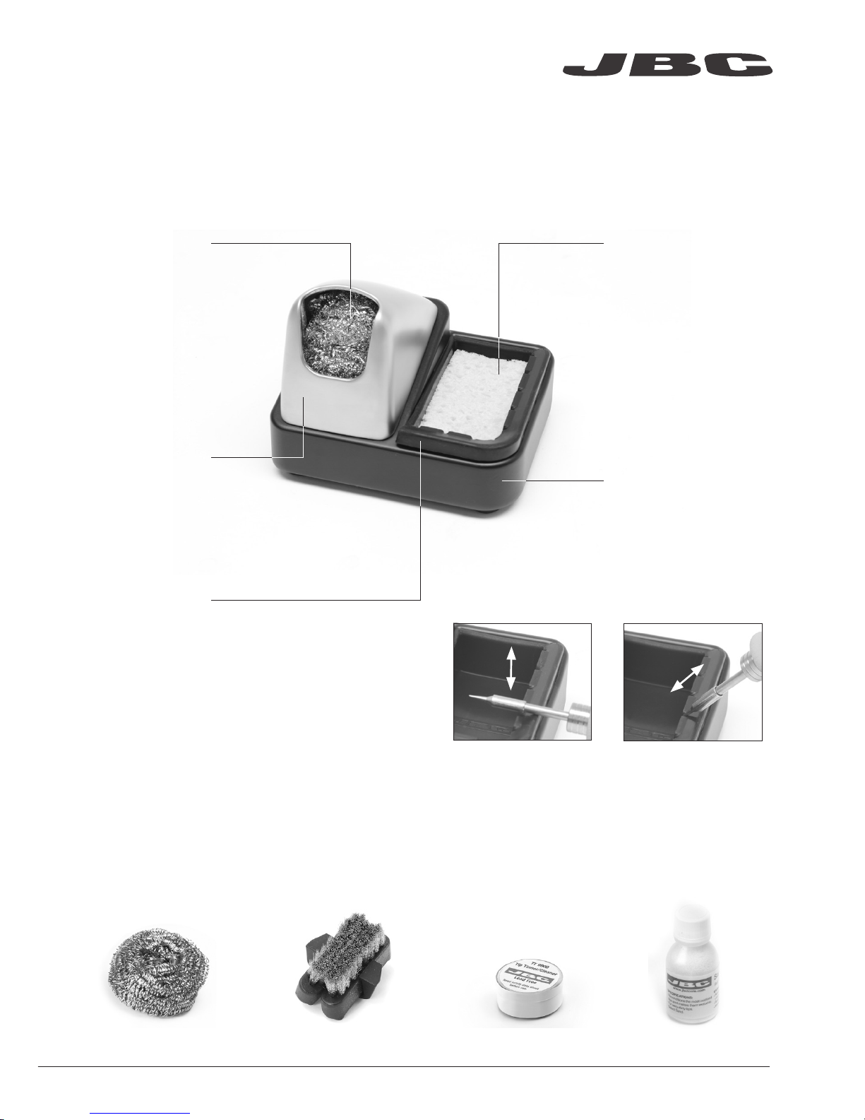
Improve thermal transfer by cleaning the tip after each solder joint.
ESD Tip Cleaner
Optional
Inox wool
Ref. CL6205
Brushes
Ref. CL6220
Tip-tinner
Ref. T T-A
Sand
Re f. C L6211
Brass wool
Ref. CL6210
Splashguard
Non-slip base
Sponge
Ref. S0354
ESD Tip Wiper
Ref. CL0240
Very effective cleaning
method. It leaves a small layer
of solder on the tip to prevent
oxidation between cleaning
and rewetting.
It prevents splashing of
solder particles. Also used
for sponge or brushes.
No need to hold the
base while cleaning tips.
The least harmful
cleaning method.
Keep the sponge damp
with distilled water when
working to avoid tip wear.
A temperature resistant receptacle
lets the operator remove excess
solder by gentle tapping or wiping.
Tapping: Wiping:
Tap to remove excess
solder.
Use the slots to remove
remaining particles.
www.jbctools.com
7
Page 8
ø 1
ø 3,5
A
B
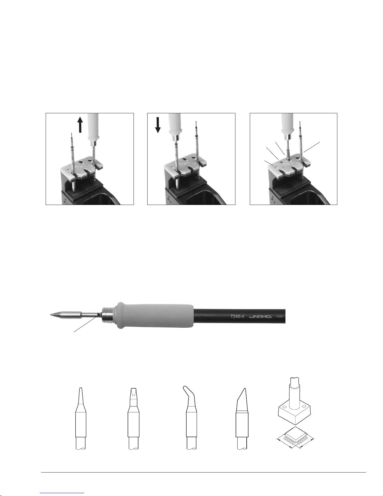
T245 Changing Cartridges
1. Removing 2. Inserting 3. Fixing
Place the handle in the
extractor and pull to remove
the cartridge.
Place the handle on top of
the new cartridge and press
down slightly.
Use the holes for fixing the
cartridge* as follows:
A. For straight C210.
B. For curved C210.
C. For curved C245.
D. For straight C245.
*Important
It is essential to insert the cartridges as far as the mark for a proper connection.
Compatible cartridges
The T245 handle works with C245 cartridges. Find the model that best suits your soldering needs in
www.jbctools.com
Round Chisel Round bent Bevel Special models
Save time and change cartridges safely without switching the station off.
Mark
B
C
A
D
8
Page 9
A ø
B ø
C560-001
C560-002
C560-003
C560-004
C560-009
C560-014
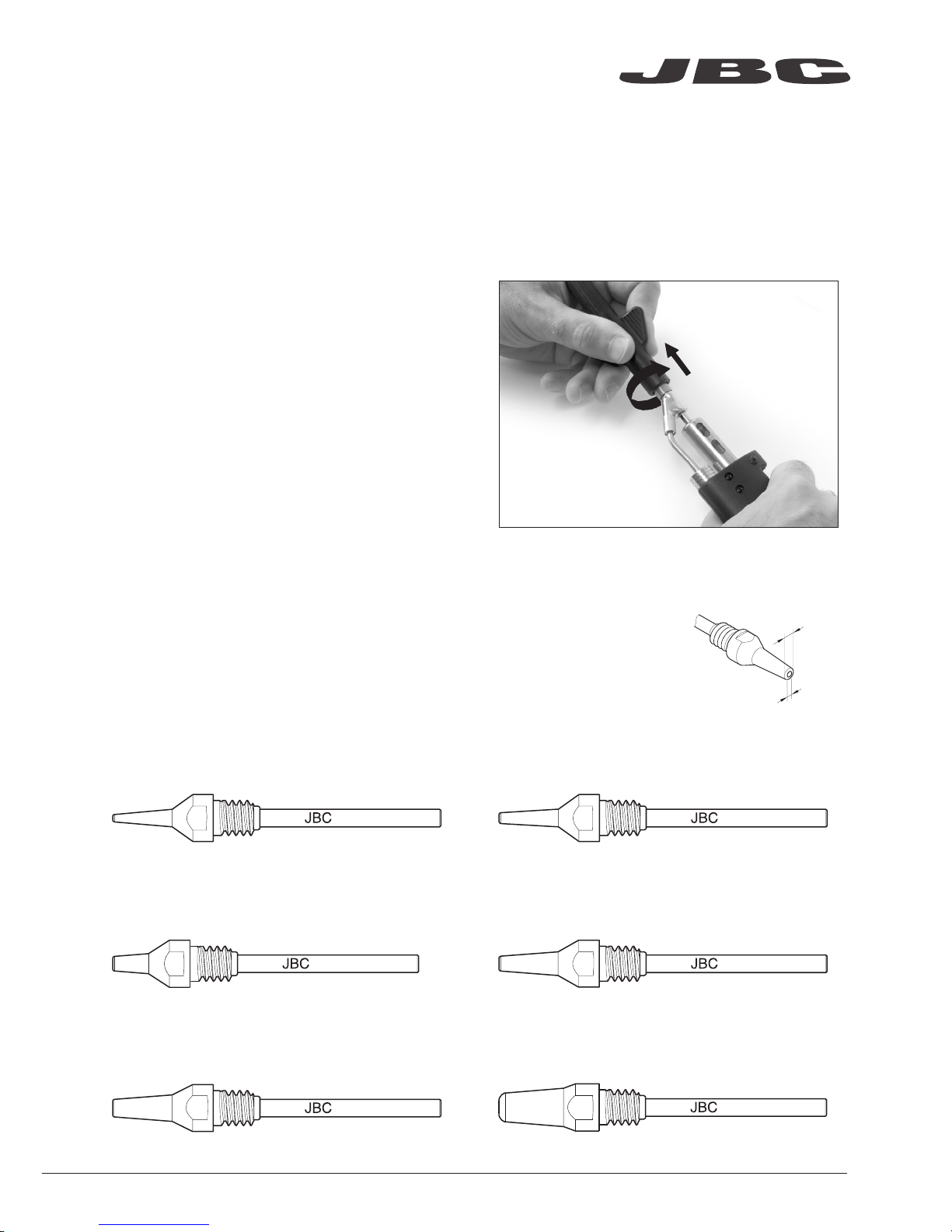
DR560 Changing Tips
This operation should be done while the tip is hot and at a minimum temperature of 250°C, so that
any tin left inside is still molten.
1. Removing
Use the special spanner to unscrew the tip.
2. Inserting
Fit the new tip and tighten with the spanner
to make sure it is air tight.
Compatible Tips
The DR560 uses C560 tips.
Find the model that best suits your soldering needs in www.jbctools.com
Here are some C560 tips in real size:
250ºC minimum
C560-001 A=1,4 B=0,6 max. pin=0,4 mm
(A=0.05 B= 0.02 max. pin= 0.01 in)
C560-002 A=1,8 B=0,8 max. pin=0,6 mm
(A=0.07 B= 0.03 max. pin= 0.02 in)
C560-003 A=2,7 B=1 max. pin=0,8 mm
(A=0.1 B= 0.04 max. pin= 0.03 in)
C560-004 A=3,2 B=1,3 max. pin=1,1 mm
(A=0.12 B= 0.05 max. pin= 0.04 in)
C560-009 A=5 B=1,3 max. pin=1,1 mm
(A=0.19 B= 0.05 max. pin= 0.04 in)
C560-014 A=2,5 B=0,8 max. pin=0,6 mm
(A=0.09 B= 0.03 max. pin= 0.02 in)
www.jbctools.com
9
Page 10
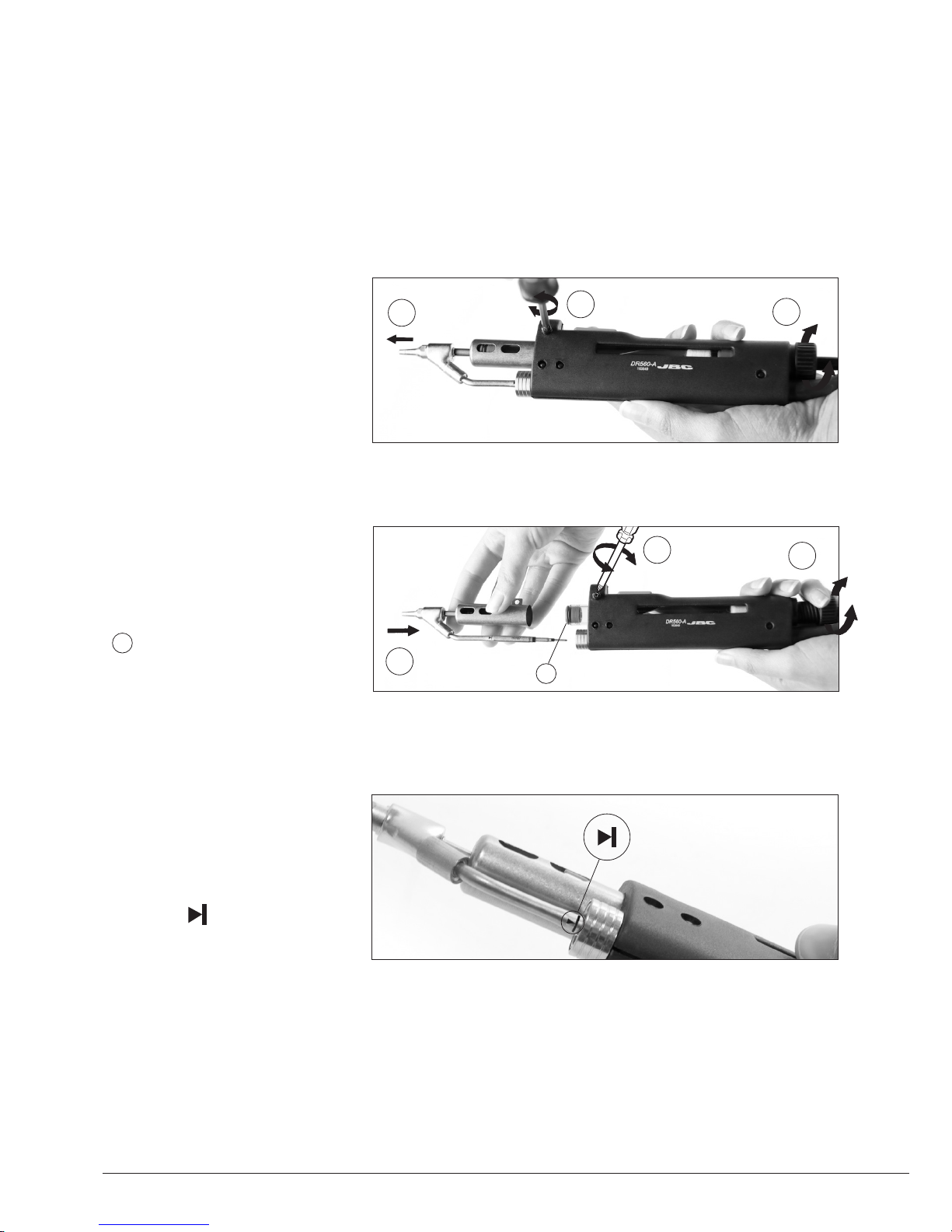
DR560 Changing the Heating Element
1. Removing
Loosen the deposit lid
(a), remove the screw (b)
and withdraw the heating
element (c).
For this operation, turn off the station or disconnect the tool and wait until the tool temperature
drops to room temperature.
2. Placing
Insert the new Heating
Element (a), tighten the screw
(b) and then the lid (c).
Important
Before placing, make sure to
insert the internal gasket into
the Glass Solder Collector.
b
a
c
b
c
a
!
!
Important
For a proper connection
it is essential to insert the
cartridge by lining it up to
the mark .
10
Page 11
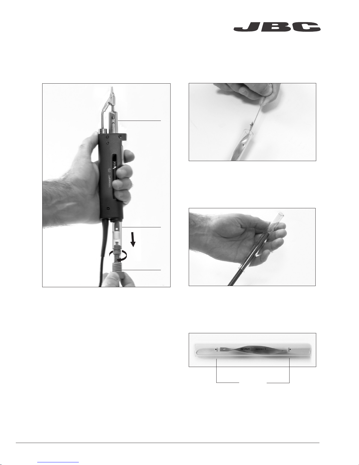
DR560 Glass Solder Collector Cleaning
1. Removing the lid
3. Inserting the glass solder collector
Check filter
Lid
Check
internal joint
2. Cleaning
Check the filter and replace it if it is dirty or
damaged.
Remove the coil and clean the inside of the glass
solder collector with the cleaning stick.
The lid must be unscrewed with the DR560 in a
vertical position.
The glass solder collector must be inserted
with coil filter in place, positioned between the
2 lines marked.
Then the whole unit must be closed by
screwing the lid.
Marks
www.jbctools.com
11
Page 12
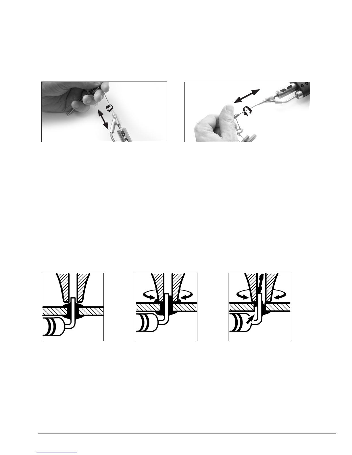
Desoldering process
Use a tip with a larger diameter than the pad to achieve maximum aspiration and thermal efficiency.
Place the tip with the
component terminal in
the hole.
After pressing the desoldering key there is a slight delay until the self-contained vacuum pump
stops. This makes sure that the vacuum circuit is completely empty. If any solder remains are left
on a terminal after desoldering it, resolder it with fresh solder and repeat the desoldering operation.
When the solder liquefies,
gently rotate the tip so that
the compo nent terminal
can be lifted off.
Press the vacuum pump
button long enough to remove
the solder.
3. Aspirating1. Placing 2. Rotating
The intake tube should be periodically cleaned by the largest rod.
DR560 Tip Care
Important
DO NOT press the vacuum pump button while tinning the desoldering tip, as the fumes given off
by the flux would quickly block the ducts and the air filter.
12
Page 13
Peripherals Port 2-DR
17:14
Pedal None
Module None
Module
MVE_a
None
1. Select the module from the list of peripheral
connections. Remember your first connection
is denoted as “a”, the second being “b”, etc.
(e.g. MVE_a, MVE_b,...)
2. Press Menu or Back to save changes.
Once set up, you can change the module
settings by entering the Peripherals Menu.
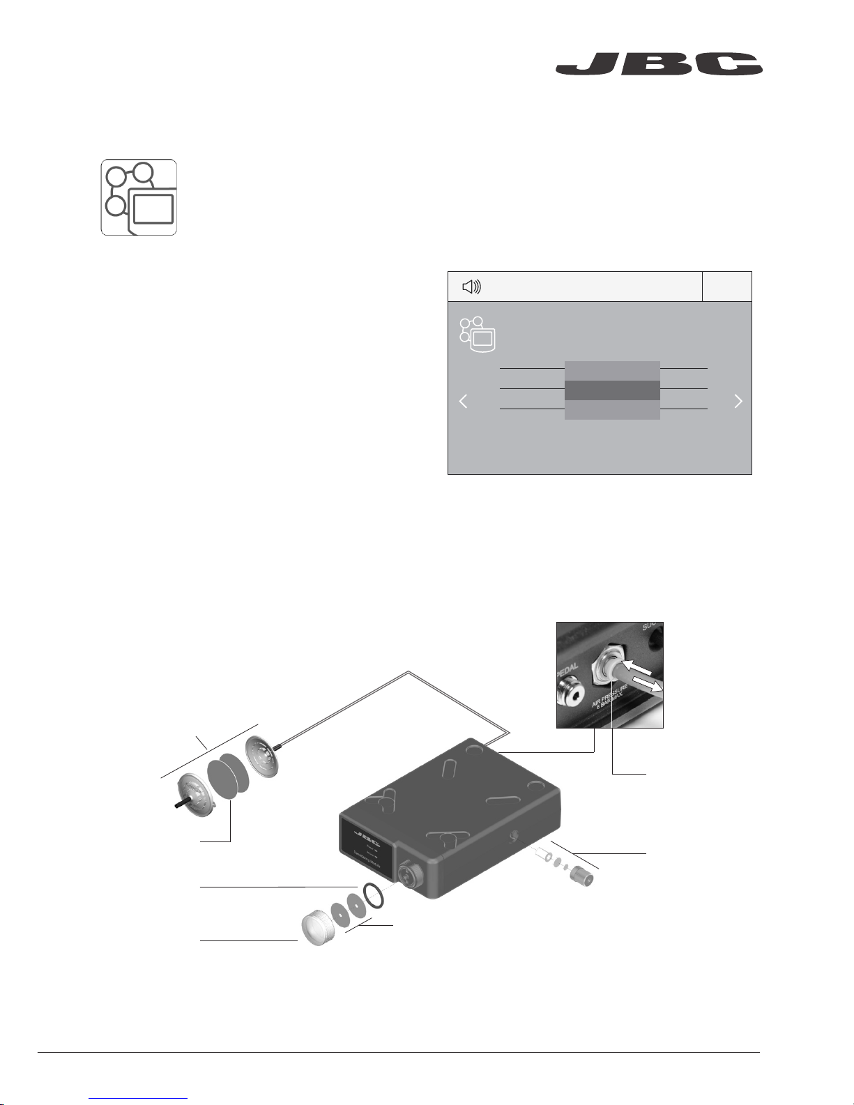
MVE Initial Setup
Peripherals
After connecting the pneumatic desoldering module (MVE-A), enter the
Peripherals Menu and select the port which you want to join with the module.
MVE Changing
the pump filters
- Use a damp cloth to keep the casing clean.
- Periodically check all cable and tube
connections.
- Keep filters clean to ensure proper solder
suction and replace them when
necessary.
Spare filters
Ref. 0005966
Cotton filters
Ref. 0781046
Suction filter
Ref. 0821830
O Ring
Ref. 0007717
Filter cover
Ref. 0004710
Escape filter
Ref. 0008446
Removing the
pneumatic tubing
- Push the release ring to remove the
pneumatic tubing.
Release ring
Important: Do not use sharp pointed objects to open the suction filter.
1
2
www.jbctools.com
13
Page 14
Port
2
T245
17:14
Sleep
Tool in the stand
Actual Temp. 180ºC
Delay to hibernation: 29:30
Port
2
T245
17:14
Hibernation
Actual Temp. 25ºC
350
ºC
Port
2
Power
45%
T245
17:14
Selected 350ºC
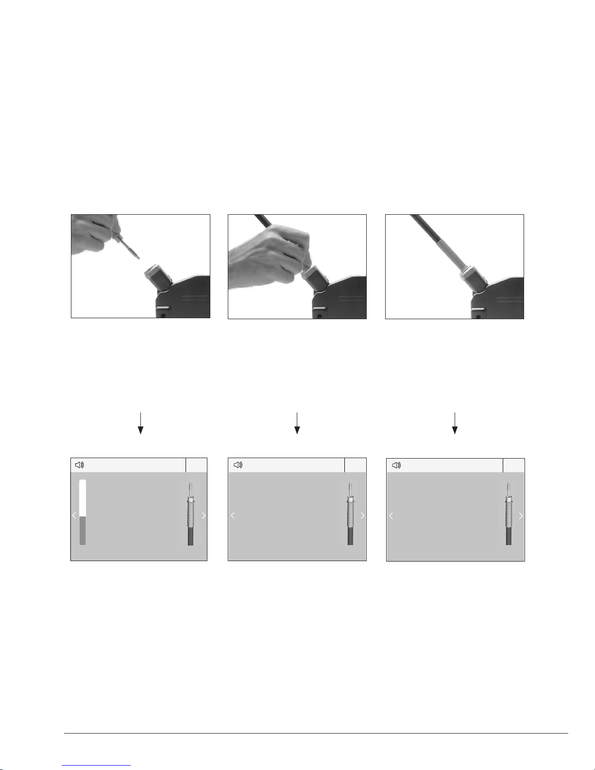
3. Hibernation
Operation
The JBC Exclusive Heating System
Our revolutionary technology is able to recover tip temperature extremely quickly. It means the user
can work at a lower temperature and improve the quality of soldering. The tip temperature is further
reduced thanks to the Sleep and Hibernation modes which increase the tip life by 5.
1. Work
2. Sleep
When the tool is lifted from the
stand the tip will heat up to the
selected temperature.
When the tool is in the stand,
the temperature falls to the
preset Sleep temperature.
After longer periods of
inactivity, the power is cut off
and the tool cools down to
room temperature.
Tools Menu:
· Set temperature limits
· Select temperature levels
Tools Menu:
· Set Sleep temperature
· Set Sleep delay
(from 0 to 9 min or no Sleep)
Tools Menu:
· Set Hibernation delay
(from 0 to 60 min or no
hibernation)
Long time in
the stand
14
Page 15
350
ºC
Port
2
Power
45%
Temp. Levels
T245
250 350 380
17:14
USB flash drive is connected.
Station is controlled by a PC.
Station is controlled by a robot.
Station software update.
Press INFO to start the process.
Warning.
Press INFO for failure description.
Error. Press INFO for failure description,
the type of error and how to proceed.
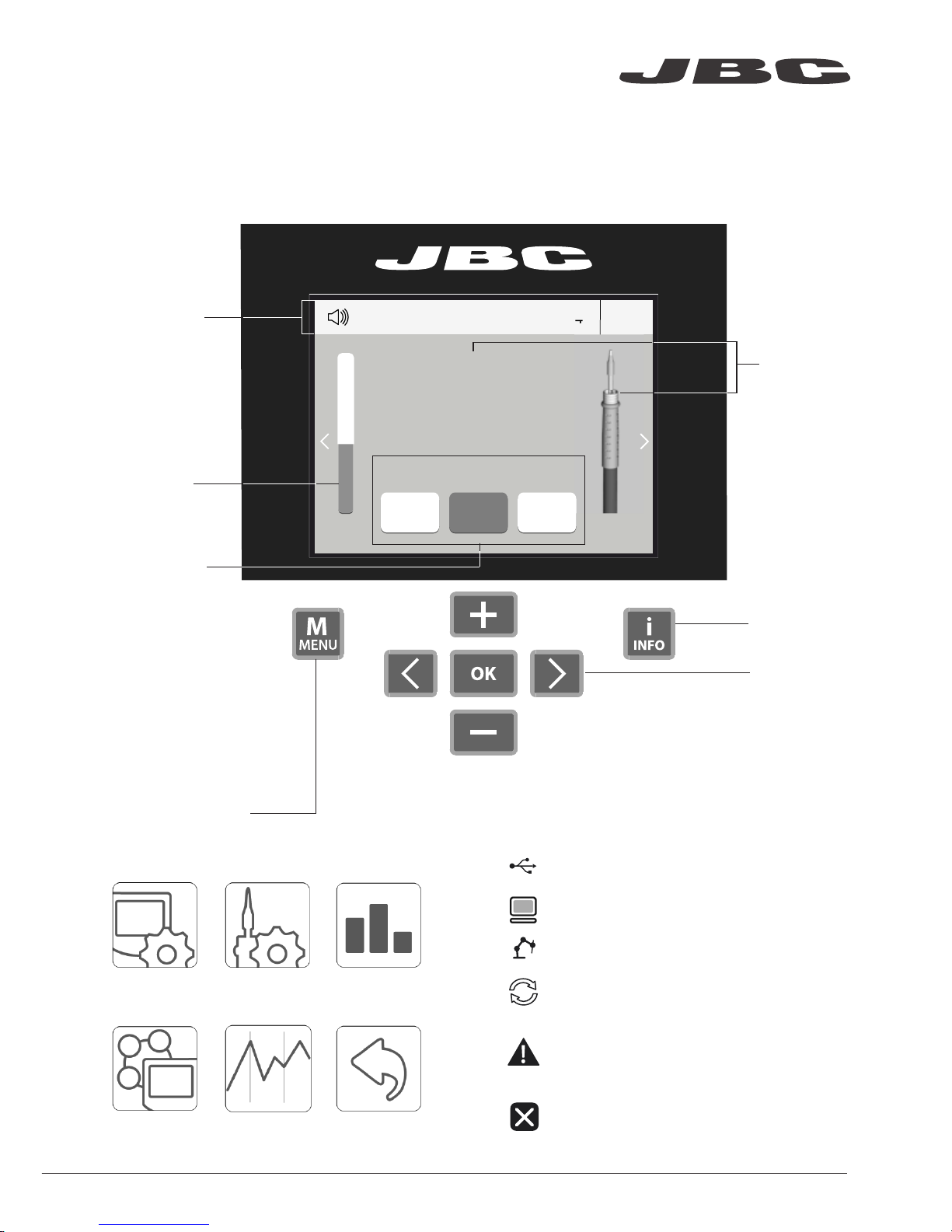
System notifications (Status Bar)Menu Options
Station
Information
Power
indicator
Tool
in use
Work Screen
Status bar
The DDE offers an intuitive user interface which provides quick access to station parameters.
Original PIN: 0105
Change port
Displayed if
temperature
levels are
activated
Station Tools Counters
ResetGraphicsPeripherals
Press INFO for each parameter description.
www.jbctools.com
15
Page 16
Port 1 - T245
450
400
350
300
250
150
100
50
200
Power Temp
17:14
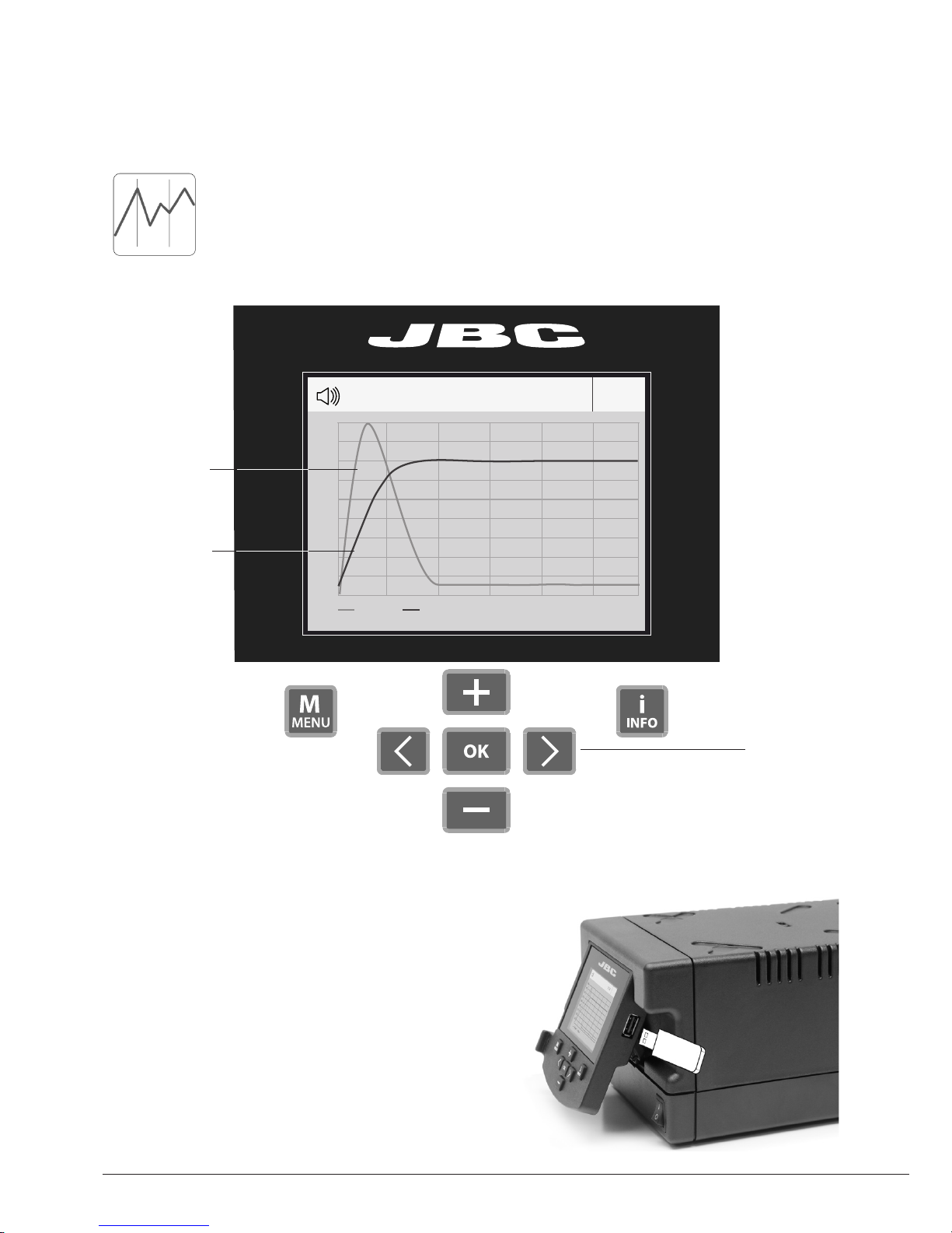
By pressing Graphics in the main MENU, temperature and power figures in real
time are displayed for each port. This helps you decide which tip to use to obtain
the best quality solder joints.
Process analysis
Export graphics
Insert a USB flash drive into the USB-A connector
to save your soldering process in csv format.
Graphics
Temperature
Power (%)
See other
port graphic
16
Page 17
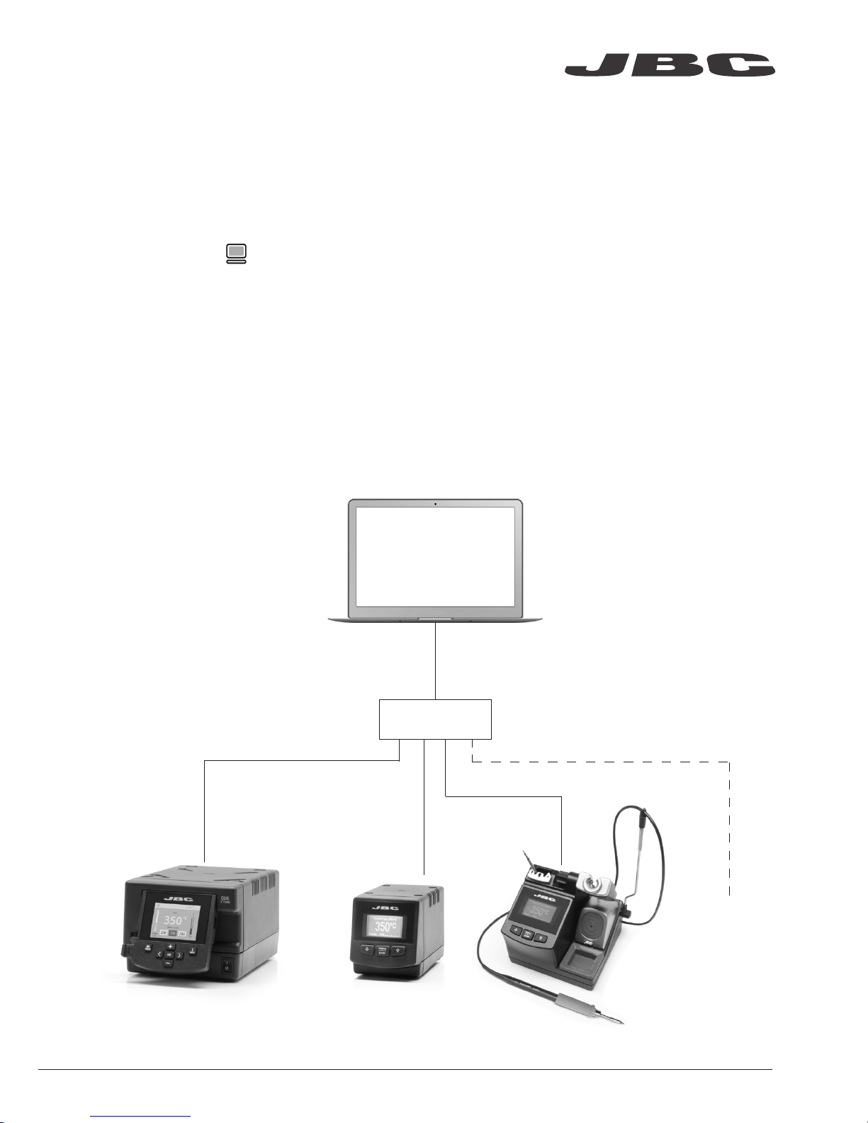
Soldering Net
Remotely manage and monitor as many stations as your PC can handle.
Functions:
- Set all the station parameters from your PC.
- Organize groups of stations and set all their parameters at the same time.
- Store specific configurations for later uses.
- Analyze the soldering graphics of the stations on your PC and export them.
1. Download the JBC Manager software and the user manual from www.jbctools.com/manager.html
2. Connect the stations via USB-B connector and the PC will automatically detect them.
3. The notification will be displayed on the station.
any JBC
station
USB Hub
JBC
Manager
Software
www.jbctools.com
17
Page 18
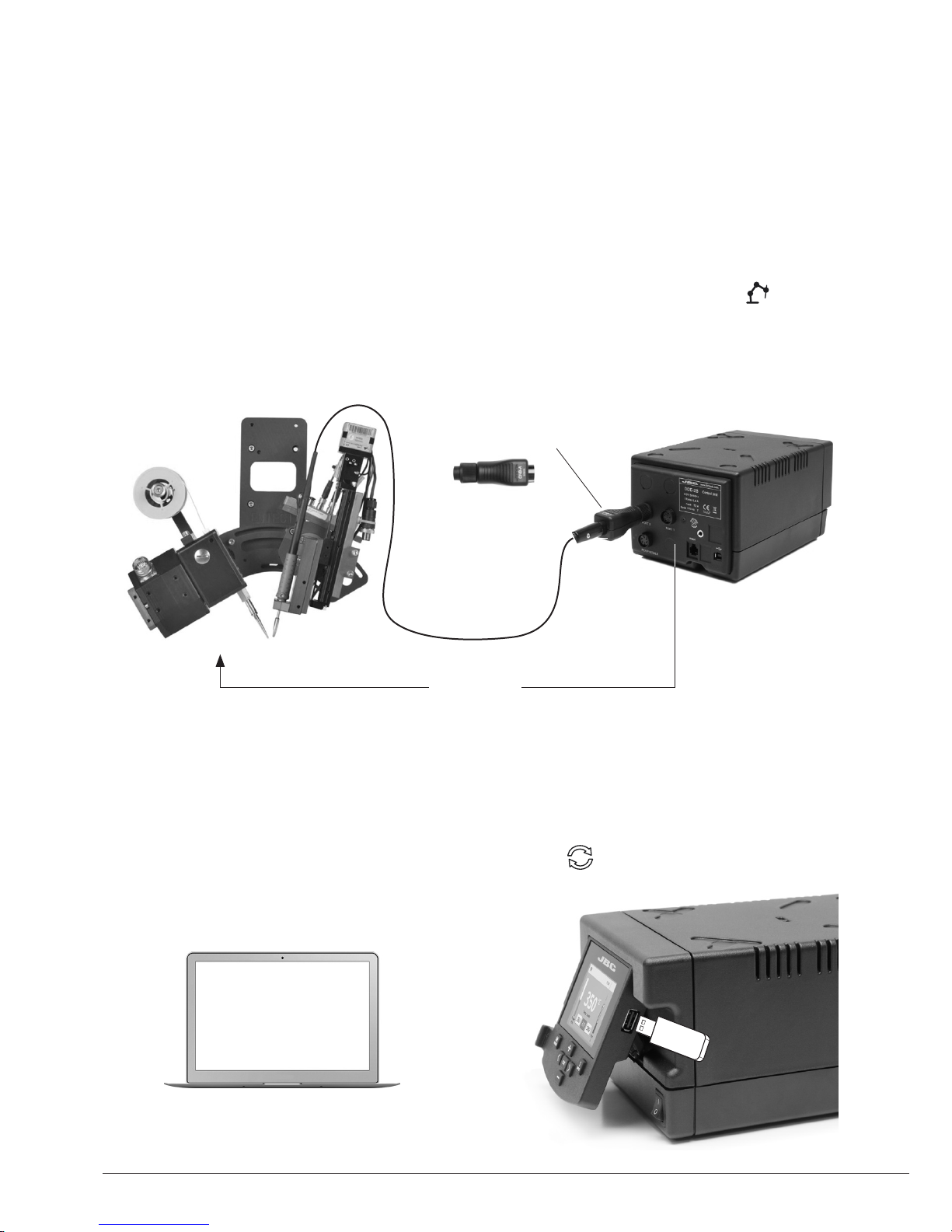
1. Connect the tool to the station port by means of the CHB-A Converter.
2. Connect your Robot system to the Robot connector (RJ12) of the station.
DB9-RJ12 Adapater available only if necessary (Ref: 0013772).
3. Enable the Robot option in the station settings and the notification will be displayed:
4. Set your Robot’s commands according to the Robot Communication Protocol, available on the
website www.jbctools.com/jbcsoftware-menu-115.html.
Manage and monitor the station using a Robotic system.
Working with Robots
Control
Unit
Robot
Update the station software
1. Download the JBC Update File from
www.jbctools.com/software.html and save
it on a USB flash drive. Preferably one with no
other files.
CHB-A
Converter
Ref. CHB-A
2. Insert the USB flash drive to the station.
The icon is diplayed while updating.
RS-232
connection
JBC
Update File
18
Page 19
Clean periodically
Maintenance
Before carrying out maintenance or storage, always allow the equipment to cool.
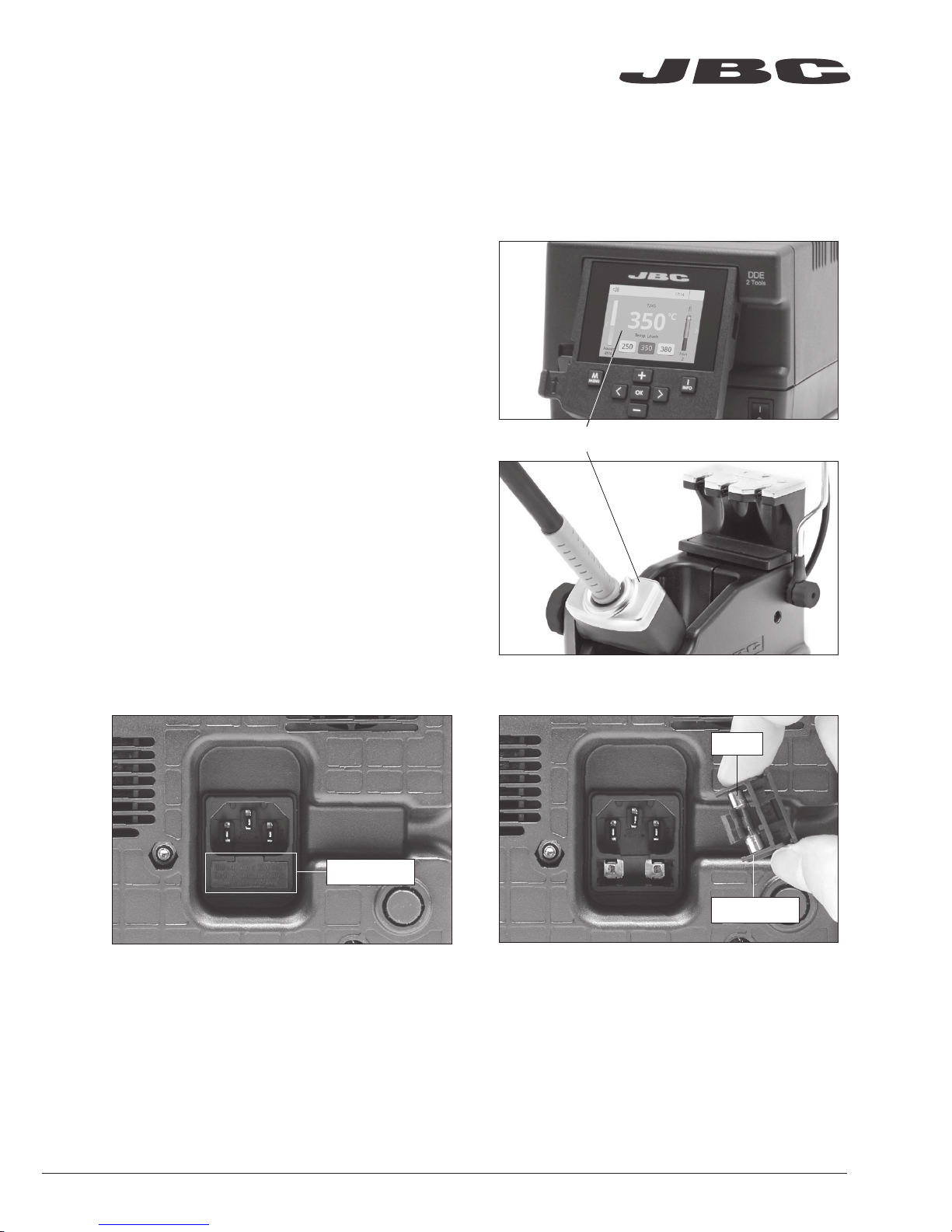
- Clean the station screen with a glass cleaner
or a damp cloth.
1. Pull off the fuse holder and remove the
fuse. If necessary use a tool to lever it off.
2. Press the new fuse into the fuse holder
and replace it in the station.
- Use a damp cloth to clean the casing and the
tool. Alcohol can only be used to clean the
metal parts.
- Periodically check that the metal parts of the
tool and stand are clean so that the station
can detect the tool status.
Fuse holder
Fuse holder
- Maintain tip surface clean and tinned prior to
storage in order to avoid tip oxidation. Rusty
and dirty surfaces reduce heat transfer to the
solder joint.
- Periodically check all cables and tubes.
Fuse
- Replace a blown fuse as follows:
- Replace any defective or damaged pieces. Use original JBC spare parts only.
- Repairs should only be performed by a JBC authorized technical service.
www.jbctools.com
19
Page 20

Safety
- Do not use the units for any purpose other than soldering or rework. Incorrect use may cause fire.
- The power cord must be plugged into approved bases. Be sure that it is properly grounded
before use. When unplugging it, hold the plug, not the wire.
- Do not work on electrically live parts.
- The tool should be placed in the stand when not in use in order to activate the sleep mode.
The soldering tip, the metal part of the tool and the stand may still be hot even when the station is
turned off. Handle with care, including when adjusting the stand position.
- Do not leave the appliance unattended when it is on.
- Do not cover the ventilation grills. Heat can cause inflamable products to ignite.
- Avoid flux coming into contact with skin or eyes to prevent irritation.
- Be careful with the fumes produced when soldering.
- Keep your workplace clean and tidy. Wear appropriate protective glasses and gloves when
working to avoid personal harm.
- Utmost care must be taken with liquid tin waste which can cause burns.
- This appliance can be used by children over the age of eight and also persons with reduced
physical, sensory or mental capabilities or lack of experience provided that they have been given
adequate supervision or instruction concerning use of the appliance and understand the hazards
involved. Children must not play with the appliance.
It is imperative to follow safety guidelines to prevent electric
shock, injury, fire or explosion.
20
Page 21

Specifications
Premium Rework Station with Pneumatic Pump
DDVE-1B / DDVE-2B / DDVE-9B
- Total weight: 8.3 Kg (18.4 lb)
DDE-1B 120V 50/60Hz. Input fuse: 4A. Output: 23.5V
DDE-2B 230V 50/60Hz. Input fuse: 2A. Output: 23.5V
DDE-9B 100V 50/60Hz. Input fuse: 5A. Output: 23.5V
- Weight: 3.8 Kg (8.4 lb)
- Dimensions: 148 x 120 x 232 mm (5.83 x 4.72 x 9.13 in)
- Output Peak Power: 150W per tool
- Temperature Range: 90-450°C (190-840 ºF)
- Idle Temp. Stability (still air) ±1.5 ºC (±3 ºF)
- Tip to ground resistance: <2 ohms
- Tip to ground voltage: <2mV RMS
- Ambient Operating Temperature: 10-40 ºC (50-104 ºF)
- USB-A / USB-B / Peripherals connectors
- RJ12 connector for Robot
MVE-A
- Weight: 0.7 Kg (1.54 lb)
- Dimensions: 145 x 55 x 225 mm (5.71 x 2.17 x 8.86 in)
- Air Pressure supply range: 4-6 Bar
- Vacuum at 6 Bar: 90% / 680 mmHg / 26.8 inHg
- Flow rate: 15 SLPM
Complies with CE standards
ESD protected
www.jbctools.com
21
Page 22

Composición
Los siguientes artículos deberían estar incluidos:
Stand Cable.......... 2 unidades
Cable del soporte
Re f. 0 0112 83
Stand ..................... 1 u
Soporte
Ref. AD-SD
Sponge ...................... 1 unidad
Esponja
Ref. S0354
Metal Brush .............. 1 unidad
Cepillo metálico
Ref. CL6217
Pneumatic Desoldering
Module ................................. 1 u
Módulo desoldador neumático
Ref. MVE-A
Tip Cleaner ......................... 1 u
Limpiador de puntas
Ref. CL6166
Module Cable .......... 1 unidad
Cable del módulo
Re f. 0 014 874
DDE Control Unit .............. 1 u
Unidad de Control DDE
Ref. DDE-1B (120V)
DDE-2B (230V)
DDE-9B (100V)
Union Flanges ......... 1 unidad
Bridas de unión
Re f. 0 0113 56
Contiene 2 bridas
Desoldering Iron .. 1 u
Desoldador
Ref. DR560-A
Stand ..................... 1 u
Soporte
Ref. DR-SD
Power cord ............... 1 unidad
Cable de Red
Ref. 0010569 (230V)
0013671 (100/120V)
General Purpose
Handle ...................... 1 u
Mango para
aplicaciones generales
Ref. T245-A
22
Page 23

Manual ....................... 1 unidad
Ref. 0017356
Suction Filter ........... 1 unidad
Filtro de aspiración
Ref. 0821830
Cotton Filter .............. 1 unidad
Filtros de algodón
Ref. 0781046
Contiene 10 filtros
DR560 Accessories
Accesorios del DR560
Re f. 0 010211
Internal gasket .... 1 unidad
Casquillo junta interior
Ref. 0019208
Contiene 2 casquillos
Filter Box .............. 1 unidad
Caja de filtros
Ref. 0780840
Contiene 10 filtros
Spanner ................. 1 unidad
Llave
Ref. 0780550
Glass solder
collector ................ 1 unidad
Depósito de estaño
Ref. 0812620
Metal solder
collector ................ 1 unidad
Depósito de metal para estaño
Ref. 0812630
Tips ..................... 3 unidades
Puntas
Ref. C560005
Ref. C560013
Ref. C560004
Cleaning stick ........... 1 unidad
Baqueta de limpieza
Ref. 0786640
Cartridges ............ 2 unidades
Cartuchos
Ref. C245903 (x1)
C245906 (x1)
Filter Box .................... 1 unidad
Caja de filtros
Ref. 0005966
Contiene 50 filtros
Venturi Filter ................... 1 unit
Filtro Venturi
Ref. 0008446
Tip cleaning set ............................. 1 unidad
Juego de limpieza de puntas
Ref. 0965970
Long Tip Cleaning set .................. 1 unidad
Juego de limpieza de puntas largo
Ref. 0965760
Premium Rework Station
with Pneumatic Pump
Ref. DDVE-B
www.jbctools.com
23
www.jbctools.com
Page 24

Stand
Soporte
Ref. DR-SD
Stand Cable
Cable del soporte
Re f. 0 0112 83
Características
Trabaje simultáneamente con 2 herramientas y enlace cada puerto con 1 módulo + 1 pedal (Peripherals).
Stand
Soporte
Ref. AD-SD
Conector RJ12 para Robot
Conector USB-B
Conexión equipotencial
Toma de corriente
Desoldering Iron
Desoldador
Ref. DR560-A
Ref. DR560-A
General
Purpose Handle
Mango para
aplicaciones
generales
Ref. T245-A
24
Page 25

Suction Filter
Filtro de succión
Ref. 0821830
Module Cable
Cable del módulo
Re f. 0 014 874
Conector USB-APantalla color TFT de 2,8”
Incline la
pantalla para
una mejor
lectura
Presión de aire (4-6 bar)
Pneumatic Desoldering Module
Módulo desoldador neumático
Ref. MVE-A
A otro periférico
Al Pedal
Ref. P-005
www.jbctools.com
25
Page 26

Cambio rápido
de cartuchos
Cambie cartuchos
sin interrumpir
su trabajo.
Soporte de
herramienta
ajustable
Se adapta a
su posición de
trabajo.
Recogecable
ajustable
Soportes ajustables
Stand
Soporte
Ref. DR-SD
Cambio rápido
de puntas
El sistema de sujeción
de puntas
facilita el cambio.
Recogecable
Mantiene el área de trabajo ordenada sin cable
Stand
Soporte
Ref. AD-SD
26
Page 27

Mejore la transferéncia térmica limpiando la punta después de cada soldadura.
Limpiador de Puntas
Opcional
Inox wool
Lana inoxidable
Ref. CL6205
Brushes
Cepillos de metal
Ref. CL6220
Tip-tinner
Reestañador de puntas
Ref. T T-A
Sand
Arena
Re f. C L6211
Brass wool
Lana de latón
Ref. CL6210
Método de limpieza muy
eficaz. Deja una fina capa
de estaño en la punta
para prevenir la oxidación
entre la limpieza y la
rehumectación.
Splashguard
Protector
anti-salpicaduras
Protege la estación de
las salpicaduras cuando
se utiliza la lana de latón.
Non-slip base
Base antideslizante
No es necesario sujetar
la base al limpiar.
Sponge
Esponja
Ref. S0354
El método de limpieza
menos dañino. Mantenga
la esponja húmeda con
agua destilada cuando
trabaje para evitar el
desgaste de la punta.
ESD Tip Wiper
Limpiador ESD
Ref. CL0240
Receptáculo resistente a la
temperatura que permite que
se pueda eliminar el exceso
de soldadura golpeando
la punta suavemente. Se
puede extraer fácilmente
para su limpieza
Golpeteo: Limpieza:
Golpee suavemente
para retirar el exceso
de soldadura.
Use las ranuras para
retirar las partículas
restantes.
www.jbctools.com
27
Page 28

ø 1
ø 3,5
A
B
Cambiar cartuchos del T245
1. Retirar 2. Insertar 3. Fijar
Coloque el soldador en el
extractor y tire para retirar el
cartucho..
Coloque el mango soldador
en la parte superior del
nuevo cartucho y presione
ligeramente.
Fije el cartucho* utilizando
los agujeros:
A. Para los C210 rectos.
B. Para los C210 curvados.
C. Para los C245 curvados.
D. Para los C245 rectos.
*Importante
Es necesario insertar el cartucho hasta la marca para una conexión correcta.
B
C
A
D
Cartuchos compatibles
El mango para soldador T245 funciona con cartuchos C245. Encuentre el modelo que mejor se
adapte a sus necesidades de soldadura en www.jbctools.com
Redondo Cincel
Redondo
curvado
Bisel
Modelos
especiales
Ahorre tiempo cambiando los cartuchos de forma rápida y segura sin apagar la estación.
Marca
28
Page 29

A ø
B ø
C560-001
C560-002
C560-003
C560-004
C560-009
C560-014
Cambiar puntas del DR560
Esta operación debe realizarse con la punta caliente (por encima de los 250°C) para que el estaño
de su interior se mantenga fundido.
250ºC minimo
1. Retirar
Desenrosque la punta utilizando la llave
suministrada.
2. Insertar
Coloque la punta nueva y enrósquela
con la llave para asegurarse que queda
hermético.
Puntas compatibles
El DR560 funciona con puntas C560.
Encuentre el modelo que mejor se adapte a sus necesidades de desoldadura
en www.jbctools.com
Algunas de las puntas C560 en tamaño real (mm):
C560-001 A=1,4 B=0,6 max. pin=0,4 mm
(A=0.05 B= 0.02 max. pin= 0.01 in)
C560-002 A=1,8 B=0,8 max. pin=0,6 mm
(A=0.07 B= 0.03 max. pin= 0.02 in)
C560-003 A=2,7 B=1 max. pin=0,8 mm
(A=0.1 B= 0.04 max. pin= 0.03 in)
C560-004 A=3,2 B=1,3 max. pin=1,1 mm
(A=0.12 B= 0.05 max. pin= 0.04 in)
C560-009 A=5 B=1,3 max. pin=1,1 mm
(A=0.19 B= 0.05 max. pin= 0.04 in)
C560-014 A=2,5 B=0,8 max. pin=0,6 mm
(A=0.09 B= 0.03 max. pin= 0.02 in)
www.jbctools.com
29
Page 30

Cambio del elemento calefactor del DR560
1. Retire
Desenrosque el tapón del
depósito (a), retire el tornillo
(b) y extraiga el elemento
calefactor (c).
Para realizar esta operación debe apagar la estación o desconectar la herramienta y esperar
que la punta esté a temperatura ambiente.
2. Coloque
Inserte el nuevo elemento
calefactor (a), apriete el tornillo
(b) y luego el tapón del
depósito (c).
Importante
Antes de colocar el depósito,
asegúrese que la junta interna
esté colocada.
b
a
c
b
c
a
Importante
Para una buena conexión, es
imprescindible introducir el
cartucho hasta la marca .
!
!
30
Page 31

Limpieza del depósito de estaño del DR560
1. Retire la tapa
3. Inserte el depósito de estaño
Compruebe
el filtro
Tap a
Compruebe
la junta interna
2. Limpieza
El filtro y la junta interna deben supervisarse
para reemplazarlos si fuera necesario, ya sea
por exceso de suciedad o por algún daño.
Retire el espiral para limpiar el interior del
depósito con la baqueta suministrada.
La tapa se debe retirar con el desoldador en
posición vertical.
El depósito se debe insertar con el espiral ya
colocado entre las dos marcas.
Concluya el proceso cerrando el depósito con
la tapa.
Marcas
www.jbctools.com
31
Page 32

Proceso de desoldadura
La punta elegida debe tener un diámetro más grande que el pad para conseguir la máxima
aspiración posible y el mejor rendimiento térmico.
Coloque la punta con el
terminal del componente
en el orificio.
Tras pulsar el botón del desoldador hay un ligero retraso hasta que la bomba de succión se
detiene. Esto asegura que el conducto de succión está completamente vacío.
Si se quedaran restos de soldadura en algun terminal después de desoldarlo, vuelva a soldarlo
con estaño nuevo y repita el proceso de desoldadura.
Cuando la soldadura se
liqüe, gire la punta con
suavidad para que el terminal
del componente se suelte.
Pulse el botón de la bomba
de succión hasta retirar
por completo los restos de
soldadura.
3. Aspirar1. Coloca r 2. Rotar
El conducto de entrada se debe limpiar periódicamente con la baqueta más larga.
Mantenimiento de puntas del DR560
Importante
NO pulse el botón de la bomba de succión mientras estaña la punta, ya que los humos producidos
por el flux bloquearían rápidamente los conductos y el filtro de aire.
32
Page 33

Peripherals Port 2-DR
17:14
Pedal None
Module None
Module
MVE_a
None
1
2
1. Seleccione el módulo del listado de
conexiones periféricas. Recuerde que su
primera conexión se indica como “a”, la
segunda como “b”, etc. (MVE_a, MVE_b,...)
2. Pulse Menu o Back para guardar los
cambios. Una vez configurado podrá
modificar cambios desde el menú Peripherals.
Puesta en marcha de la bomba MVE
Peripherals
Tras conectar el módulo desoldador neumático (MVE-A), entre en el menú de
Peripherals y seleccione el puerto con el que desee enlazar el módulo.
Cambiar los filtros
de la bomba MVE
- Limpie la carcasa con un paño húmedo.
Asegúrese utilizar un paño suave para el
frontal.
- Revise periódicamente los cables y tubos.
- Mantenga los filtros limpios para garantizar
una correcta aspiración y reemplácelos si
fuera necesario.
Filtros
Ref. 0005966
Filtros de algodón
Ref. 0781046
Filtro de aspiración
Ref. 0821830
Anillo
Ref. 0007717
Tapa de filtros
Ref. 0004710
Filtro
de escape
Ref. 0008446
Cambiar el tubo del módulo
- Presione el anillo de liberación para extraer
el tubo del módulo.
Anillo
de liberación
Importante: No utilice objetos punzantes para abrir el filtro de aspiración.
www.jbctools.com
33
Page 34

Port
2
T245
17:14
Sleep
Tool in the stand
Actual Temp. 180ºC
Delay to hibernation: 29:30
Port
2
T245
17:14
Hibernation
Actual Temp. 25ºC
350
ºC
Port
2
Power
45%
T245
17:14
Selected 350ºC
3. Hibernación
Funcionamiento
El exclusivo sistema calefactor de JBC
Nuestra tecnología revolucionaria es capaz de recuperar la temperatura de la punta de forma
extremadamente rápida. Esto significa que el usuario puede trabajar a una temperatura más baja
y mejorar la calidad de la soldadura. Esta temperatura se reduce aún más gracias a los modos de
Sleep e Hibernation que incrementan hasta 5 veces la vida de las puntas.
1. Tra bajo 2. Sleep
Al levantar la herramienta
del soporte, la punta se
calienta hasta la temperatura
seleccionada.
Si la herramienta permenece
en el soporte, la temperatura
se reduce a la temperatura
predefinida.
Luego de largos períodos de
inactividad, el suministro de
energía se corta y la punta
se enfría hasta temperatura
ambiente.
Menu To ols:
· Configure límites de
temperatura.
· Seleccione niveles de
temperatura.
Menu To ols:
· Configure la temperatura
de Sleep
· Configure el tiempo de
retraso de Sleep (de 0 a 9
min o ninguno)
Menu To ols:
· Configure el retraso de
Hibernación (de 0 a 60 min
o ninguno)
Mucho tiempo
en el soporte
34
Page 35

350
ºC
Port
2
Power
45%
Temp. Levels
T245
250 350 380
17:14
Unidad de memoria USB conectada.
Estación controlada por un PC.
Estación controlada por un robot.
Actualización del software de la estación.
Pulse INFO para iniciar el proceso.
Aviso.
Pulse INFO para la descripción del fallo.
Error. Pulse INFO para la descripción del
fallo, el tipo de error y cómo proceder.
Notificaciones (Barra de estado)Opciones de Menú
Ayuda de
la estación
Indicador de
potencia
Herramienta
en uso
Pantalla de trabajo
Barra
de estado
La DDE-B presenta una interfaz de usuario intuitiva y ofrece un rápido acceso a los parámetros.
PIN original: 0105
Cambio
de puerto
Se muestra si
los niveles de
temperatura
están activos
Station Tools Counters
ResetGraphicsPeripherals
Pulse INFO para la descripción de parámetros.
www.jbctools.com
35
Page 36

Port 1 - T245
450
400
350
300
250
150
100
50
200
Power Temp
17:14
Pulsando sobre Graphics en el menú principal, se muestran las respuestas de
temperatura y potencia en tiempo real de cada puerto. Esto le ayudará a decidir cuál
es la punta más adecuada para obtener la mejor calidad en sus soldaduras.
Análisis del proceso
Exporte gráficos
Inserte una unidad de memoria USB para guardar
su proceso de trabajo en formato csv.
Graphics
Temperatura
Potencia (%)
Vea el gráfico del
otro puerto
36
Page 37

Red de soldadura
Gestione y monitorice tantas estaciones como soporte su PC.
Funciones:
- Configure todos los parámetros de la estación desde su PC.
- Organice grupos de estaciones y configure todos sus parámetros al mismo tiempo.
- Guarde configuraciones específicas para usos posteriores.
- Analice gráficos del proceso de soldadura de las estaciones desde su PC y expórtelos.
1. Descargue el software JBC Manager y el manual de usuario de www.jbctools.com/manager.html
2. Conecte las estaciones a través del conector USB-B y el PC las detectará automáticamente.
3. La notificación se mostrará en la estación.
cualquier
estación
JBC
USB Hub
JBC
Manager
Software
www.jbctools.com
37
Page 38

1. Conecte la herramienta a la estación utilizando el convertidor CHB-A.
2. Conecte su sistema robotizado al conector Robot de la estación (RJ12).
Si lo necesita, el adaptador DB9-RJ12 está disponible (Ref: 0013772).
3. Active la opción de robot en la estación y se mostrará la siguiente notificación:
4. Configure su sistema robotizado según el Protocolo de Comunicación para Robots,
que encontrará en www.jbctools.com/jbcsoftware-menu-115.html.
Gestione y monitorice la estación por medio de un sistema robotizado.
Trabajar con Robots
Unidad
de Control
Robot
Actualice el software de la estación
1. Descargue el archivo de actualización de
www.jbctools.com/software.html cuando
esté disponible y guá rdelo en una unidad de
memoria USB (preferentemente una sin
otros archivos).
Convertidor
CHB-A
Ref. CHB-A
2. Inserte la unidad de memoria USB.
La notificación se muestra mientras
se actualiza el software.
Conexión
RS-232
JBC
Update File
38
Page 39

Mantenga limpio
Mantenimiento
Antes de realizar tareas de mantenimiento o almacenar, desconecte el equipo y déjelo enfriar.
1. Tire del portafusible para retirar el fusible.
Si lo precisa, utilice una pequeña palanca.
2. Sustituya el fusible y coloque de nuevo el
portafusibles en su sitio.
- Use un paño húme do para limpiar la pantalla
del equipo, la carcasa y la herramienta.
Puede utilizar alcohol solamente en las
partes metálicas.
- Compruebe periódicamente que las partes
metálicas de la herramienta y del soporte
están limpias. Así la estación puede detectar
el estado de la herramienta y activar los
modos de Sleep o Hibernation.
- Mantenga la punta limpia y estañada la
para evitar su oxidación. Las superfícies
sucias reducen la transferencia térmica a la
soldadura.
- Revise periódicamente los tubos y cables.
Portafusible
Portafusible
Fusible
- Cambie cualquier pieza defectuosa o dañada. Utilice solamente recambios originales de JBC.
- Cualquier reparación sólo se podrá realizar por un servicio técnico oficial JBC.
- Cambie el fusible fundido de la siguiente manera:
www.jbctools.com
39
Page 40

Seguridad
- No utilice el equipo para otros fines que no sea la soldadura o reparación. El uso incorrecto
puede causar fuego.
- El cable de red debe enchufarse en bases homologadas. Asegúrese de que está conectado a
tierra correctamente antes de su uso. Al retirarlo, tire del conector, no del cable.
- No trabaje con tensión.
- La herramienta debe permanecer en el soporte mientras no está en uso con el fin de activar el modo
de Sleep o Hibernación. El cartucho y las partes metálicas de la herramienta o del soporte pueden
estar calientes incluso cuando con la estación apagada. Manipule con cuidado, incluso cuando se
ajusta la posición del soporte.
- No deje el aparato desatendido cuando está en funcionamiento.
- No cubra las rejillas de ventilación. El calor puede causar que los productos inflamables se enciendan.
- Evite el contacto del Flux con la piel o los ojos para prevenir la irritación.
- Tenga cuidado con el humo producido al trabajar.
- Mantenga su lugar de trabajo limpio y ordenado. Use gafas y guantes de protección adecuados.
Así evitará cualquier daño.
- Tenga cuidado con los restos de estaño líquido. En contacto con la piel, puede causar quemaduras.
- Este aparato puede ser utilizado por personas a partir de 8 años y también por aquellas
personas con movilidad reducida o capacidades físicas, sensoriales o mentales limitadas o
con falta de experiencia y conocimientos siempre y cuando reciban supervisión o instrucciones
relativas al uso del aparato de una manera segura y entiendan los riesgos que implica. Los niños
no deben jugar con el aparato.
- Los niños no deberán realizar tareas de mantenimiento sin supervisión.
Es necesario cumplir estas normas de seguridad para prevenir cualquier
choque eléctrico, heridas, fuego o explosiones.
40
Page 41

Especificaciones
Premium Rework Station with Pneumatic Pump
Estación de reparación con bomba neumática
DDVE-1B / DDVE-2B / DDVE-9B
- Peso total: 8,3 Kg (18.4 lb)
DDE-1B 120V 50/60Hz. Fusible de entrada: 4A. Salida: 23.5V
DDE-2B 230V 50/60Hz. Fusible de entrada: 2A. Salida: 23.5V
DDE-9B 100V 50/60Hz. Fusible de entrada: 5A. Salida: 23.5V
- Peso: 3,8 Kg (8.4 lb)
- Dimensiones: 148 x 120 x 232 mm (5.83 x 4.72 x 9.13 in)
- Potencia máxima de pico: 150W por herramienta
- Rango de temperatura: 90-450°C (190-840 ºF)
- Estabilidad de temperatura en reposo: ±1.5 ºC (±3 ºF)
- Resistencia punta a tierra: <2 ohms
- Tensión en punta: <2mV RMS
- Temperatura ambiente de trabajo: 10-40 ºC (50-104 ºF)
- Conectores USB-A / USB-B / Peripherals (periféricos)
- Conector RJ12 para Robot
MVE-A
- Peso: 0,7 Kg (1.54 lb)
- Dimensiones: 145 x 55 x 225 mm (5.71 x 2.17 x 8.86 in)
- Rango de presión de aire: 4-6 Bar
- Vacío a 6 Bar: 90% / 680 mmHg / 26.8 inHg
- Caudal: 15 SLPM
Cumple con las normativas CE
Seguridad ESD
www.jbctools.com
41
Page 42

Packliste
Die folgenden Artikel sollten enthalten sein:
Stand Cable................ 2 Stück
Anschlusskabel
Re f. 0 0112 83
Stand .................. 1 St.
Ablageständer
Ref. AD-SD
Sponge ........................ 1 Stück
Schwamm
Ref. S0354
Metal Brush ................ 1 Stück
Metallbürste
Ref. CL6217
Pneumatic Desoldering
Module ......................... 1 Stück
Druckluft Entlöt Modul
Ref. MVE-A
Tip Cleaner ................. 1 Stück
Lötspitzenreiniger
Ref. CL6166
Module Cable ............ 1 Stück
Modulkabel
Re f. 0 014 874
DDE Control Unit ...... 1 Stück
DDE Versorgungseinheit
Ref. DDE-1B (120V)
DDE-2B (230V)
DDE-9B (100V)
Union Flanges ........... 1 Stück
Kabelclips
Re f. 0 0113 56
Sie enthält
2 Kabelclips
Desoldering Iron .. 1 St.
Entlötkolben
Ref. DR560-A
Stand .................. 1 St.
Ablageständer
Ref. DR-SD
Power cord ................. 1 Stück
Netzkabel
Ref. 0010569 (230V)
0013671 (100/120V)
General Purpose
Handle ................... 1 St.
Universal-Handstück
Ref. T245-A
42
Page 43

Handbuch ................... 1 Stück
Ref. 0017356
Suction Filter ............. 1 Stück
Saugfilter
Ref. 0821830
Cotton Filter ................ 1 Stück
Baumwollfilter
Ref. 0781046
Sie enthält 10 filter
DR560 Accessories
DR560 Zubehör
Re f. 0 010211
Internal gasket ...... 1 Stück
Dichtung für Entlötkolben
Ref. 0019208
Sie enthält 2 dichtung
Filter Box ................ 1 Stück
Ref. 0780840
Sie enthält 10 filter
Spanner ...................... 1 Stück
Entlötspitzen-Wechselwerkzeug
Ref. 0780550
Glass solder
collector .................. 1 Stück
Glasrohr
Ref. 0812620
Metal solder
collector .................. 1 Stück
Metallrohr für Entlötkolben
Ref. 0812630
Tips ........................... 3 Stück
Spitzen
Ref. C560005
Ref. C560013
Ref. C560004
Cleaning stick ............. 1 Stück
Reinigungsstab
Ref. 0786640
Cartridges ................... 2 Stück
Kartuschen
Ref. C245903 (x1)
C245906 (x1)
Filter Box ...................... 1 Stück
Ref. 0005966
Sie enthält 50 filter
Venturi Filter ................ 1 Stück
Filtro Venturi
Ref. 0008446
Tip cleaning set ............................... 1 Stück
Lötspitzen-Reinigungsset
Ref. 0965970
Long Tip Cleaning set .................... 1 Stück
Reinigungswerkzeug, Nadeln
Ref. 0965760
Premium Rework Station
with Pneumatic Pump
Ref. DDVE-B
www.jbctools.com
43
www.jbctools.com
Page 44

Stand
Ablage
Ref. DR-SD
Stand Cable
Anschlusskabel
Re f. 0 0112 83
Merkmale
Arbeiten Sie gleichzeitig mit bis zu 2 Werkzeugen und verbinden Sie jeden Stationsport mit 1 Modul
+ 1 Fußschalter (Peripheriegeräte).
Stand
Ablage
Ref. AD-SD
RJ12-Buchse für Roboter
USB-B-Anschluss
Potenzialausgleichsbuchse
Netzkabelbuchse
Desoldering Iron
Entlötkolben
Ref. DR560-A
Ref. DR560-A
General
Purpose Handle
Universal-Handstück
Ref. T245-A
44
Page 45

Suction Filter
Saugfilter
Ref. 0821830
Module Cable
Modulkabel
Re f. 0 014 874
USB-A Anschluss2,8” Farb TFT Bildschirm
Das Display
zum einfachen
Ablesen kippen
Luftdruck (4-6 bar)
Pneumatic Desoldering Module
Druckluft Entlöt Modul
Ref. MVE-A
Zu einem anderen
Peripheriegerät
Zum Fußschalter
Ref. P-005
www.jbctools.com
45
Page 46

Spitzen-Schnellwechsler
Ermöglicht Ihnen
Spitzenwechsel ohne
Arbeitsunterbrechung.
Verstellbarer
Werkzeughalter
Optimiert Ihre
Arbeitsposition.
Verstellbarer
Kabel-ausleger
Verstellbare Ablagen
Stand
Ablage
Ref. DR-SD
Spitzen-Schnellwechsler
Spitzenfixiersystem
für einfachen Wechsel.
Kabelausleger
Sorgt für einen kabelfreien Arbeitsbereich
Stand
Ablage
Ref. AD-SD
46
Page 47

Verbessern Sie die Wärmeübertragung durch Reinigung der Lötspitze nach jeder Lötverbindung.
Spitzenreiniger
Wahlweise
Inox wool
Edelstahlwolle
Ref. CL6205
Brushes
Bürstenl
Ref. CL6220
Tip-tinner
Lötspitzenverzinner
Ref. T T-A
Sand
Re f. C L6211
Brass wool
Messinggeflecht
Ref. CL6210
Sehr wirksame
Reinigungsmethode. Lässt
eine dünne Lotschicht auf
der Spitze zurück, wodurch
die Oxidation zwischen
Reinigung und Rückfeuchten
vermieden wird.
Splashguard
Spritzschutz
Verhindert Lötpartikelspritzer.
Auch für Schwamm oder
Bürsten benutzt.
Non-slip base
Rutschfeste
Bodenauflage
Während der
Lötspitzenreinigung ist
es nicht notwendig, die
Bodenauflage festzuhalten.
Sponge
Schwamm
Ref. S0354
Die schonendste
Reinigungsmethode.
Halten Sie den
Schwamm bei der
Arbeit mit destilliertem
Wasser feucht, um
Spitzenverschleiß zu
vermeiden.
ESD Tip Wiper
ESD-Lötspitzenabstreifer
Ref. CL0240
Ein temperaturfester Behälter
ermöglicht dem Bediener
durch leichtes Abklopfen oder
Abstreifen überschüssiges
Lot zu entfernen.
Abklopfen: Abstreifen:
Klopfen Sie ab, um
überschüssiges Lot zu
entfernen.
Benutzen Sie die
Aussparungen, um noch
vorhandene Partikel zu
entfernen.
www.jbctools.com
47
Page 48

ø 1
ø 3,5
A
B
T245 Auswechseln der Kartuschen
1. Entfernen 2. Einsetzen 3. Fixieren
Positionieren Sie das Handstück im Abzieher und ziehen
Sie zum Entfernen der
Kartusche.
Positionieren Sie das
Handstück auf der neuen
Kartusche und drücken Sie
mit leichtem Druck nach
unten.
Benutzen Sie die
Aussparungen zur Fixierung
der Kartusche* wie folgt:
A. Für gerade C210.
B. Für bogenförmige C210.
C. Für bogenförmige C245.
D. Für gerade C245.
*Wichtig
Es ist wichtig, die Kartuschen für eine einwandfreie Verbindung genau bis zur Markierung einzustecken.
B
C
A
D
Kompatible Kartuschen
Der Lötkolben T245 arbeitet mit C245 Spitzen. Finden Sie das passende Modell für Ihren Lötbedarf
unter www.jbctools.com
Rund Meißelförmig
Rund
gebogen
Abgeschrägt Spezialmodelle
Sparen Sie Zeit und wechseln Sie sicher Kartuschen, ohne die Station auszuschalten.
Markierung
48
Page 49

A ø
B ø
C560-001
C560-002
C560-003
C560-004
C560-009
C560-014
DR560 Tipps zum Auswechseln
Diese Operation sollte ausgeführt werden, solange die Spitze heiß ist, bei mindestens 250 °C,
sodass jegliches darin befindliche Zinn im geschmolzenen Zustand ist.
1. Entfernen
Schrauben Sie die Spitze mit dem
Wechsel-Werkzeug los.
2. Einsetzen
Passen Sie die neue Spitze ein, ziehen
Sie sie mit dem Wechsel-Werkzeug an,
um ihre Luftundurchlässigkeit zu
gewährleisten.
Kompatible Spitzen
Der Entlötkolben DR560 arbeitet mit C560 Spitzen.
Finden Sie das passende Modell für Ihren Lötbedarf unter
www.jbctools.com
Hier sehen Sie einige C560-Spitzen maßstabsgetreu (mm):
250ºC mindest
C560-001 A=1,4 B=0,6 max. pin=0,4 mm
(A=0.05 B= 0.02 max. pin= 0.01 in)
C560-002 A=1,8 B=0,8 max. pin=0,6 mm
(A=0.07 B= 0.03 max. pin= 0.02 in)
C560-003 A=2,7 B=1 max. pin=0,8 mm
(A=0.1 B= 0.04 max. pin= 0.03 in)
C560-004 A=3,2 B=1,3 max. pin=1,1 mm
(A=0.12 B= 0.05 max. pin= 0.04 in)
C560-009 A=5 B=1,3 max. pin=1,1 mm
(A=0.19 B= 0.05 max. pin= 0.04 in)
C560-014 A=2,5 B=0,8 max. pin=0,6 mm
(A=0.09 B= 0.03 max. pin= 0.02 in)
www.jbctools.com
49
Page 50

DR560 Wechsel des Heizelements
1. Entnehmen
Schrauben Sie die
Abdeckung ab (a), öffnen
Sie die Schraube (b)
und entnehmen Sie das
Heizelement (c).
Um diese Operation durchzuführen, die Station ausschalten oder das Werkzeug vom Netz trennen.
2. Einsetzen
Setzen Sie das neue
Heizelement ein (a), befestigen
Sie die Schraube (b) und
schrauben Sie die Abdeckung
wieder fest (c).
Wichtig
Bevor Sie das Glasrohr
einsetzen, stellen Sie sicher,
daß die innere Dichtung
eingesetzt ist.
b
a
c
c
b
a
!
!
Wichtig
Setzen Sie das Heizelement
bis zur Markierung ein, um
eine korrekte Verbindung zu
gewährleisten .
50
Page 51

DR560 Reinigung des Glasrohrs
1. Abdeckung entfernen
3. Einsetzen des Glasrohrs
Filter prüfen
Abdeckung
Innendichtung
prüfen
2. Reinigung
Der Filter und die Innendichtung müssen
geprüft werden und bei Verschmutzung oder
Beschädigung ausgetauscht werden.
Entnehmen Sie die Spirale, um das Innere
des Glasrohrs mit dem zum Lieferumfang
gehörenden Stab zu reinigen.
Die Abdeckung muss entfernt werden, wenn
der Entlötkolben DR560 in senkrechter
Position steht.
Das Glasrohr muss mit korrekt ausgerichtetem
- zwischen den 2 auf dem Glasrohr markierten
Linien - Spiralfilter eingesetzt werden.
Dann muss die ganze Einheit durch
Einschrauben der Abdeckung verschlossen
werden.
Markierungen
www.jbctools.com
51
Page 52

Entlöt-Verfahren
Benutzen Sie eine Spitze mit einem größeren Durchmesser als das Lötauge, um so maximale
Saugleistung und thermische Effizienz zu erzielen.
Platzieren Sie die
Spitze mit dem
Baugruppenterminal
innerhalb der Öffnung.
Nach Betätigung der Entlöttaste tritt eine kurze Verzögerung ein, bis die eigenständige Vakuumpumpe abschaltet. Dies gewährleistet, dass der Vakuumkreislauf vollständig leer ist. Falls nach
dem Entlöten irgendein Lotrest auf einem Terminal zurückbleiben sollte, mit frischem Lot löten
und den Entlöt-Vorgang wiederholen.
Wenn das Lot flüssig wird,
drehen Sie vorsichtig
die Entlötspitze, sodass
das Baugruppenterminal
angehoben werden kann.
Drücken Sie lang genug den
Pumpenknopf, um das Lot zu
entfernen.
3. Saugen1. Einsetzen 2. Drehen
Die Ansaugleitung sollte regelmäßig mit dem größten Stab gereinigt werden.
DR560 Spitzenpflege
Wichtig
Betätigen SIE NICHT den Druckknopf der Vakuumpumpe, während die Entlötspitze verzinnt
wird, da der aus dem Flussmittel entweichende Rauch schnell die Leitungen und den Luftfilter
blockieren würde.
52
Page 53

Peripherals Port 2-DR
17:14
Pedal None
Module None
Module
MVE_a
None
1. Wählen Sie das Modul aus der Liste der
Anschlüsse von Peripheriegeräten aus.
Denken Sie daran, dass Ihr erster
Anschluss als “a”, der zweite als “b”, usw.
bezeichnet werden (d.h. MVE_a, MVE_b,...)
2. Drücken Sie Menu oder Back, um die
Änderungen zu speichern. Nach
vorgenommener Konfiguration, können Sie
die Moduleinstellungen ändern, indem Sie
in das Menü Peripherals gehen.
MVE Startkonfiguration
Peripherals
Nachdem die Druckluft Entlöt Modul (MVE-A) angeschlossen wurde, gehen Sie
in das Menü Peripherals und wählen den Port aus, den Sie mit dem Modul
verbinden möchten.
MVE Wechsel der
Pumpenfilter
- Halten Sie das Gehäuse sauber, indem Sie
einen feuchten Lappen benutzen. Bitte darauf
achten dass Sie ein weiches Tuch für die
Vorderseite benutzen.
- Überprüfen Sie regelmäßig alle Kabel und
Schlauchanschlüsse. Halten Sie die Filter sauber,
um einwandfreie Lotabsaugung zu gewährleisten
und tauschen Sie sie bei Bedarf aus.
Ersatzfilter
Ref. 0005966
Baumwollfilter
Ref. 0781046
Saugfilter
Ref. 0821830
O-Ring
Ref. 0007717
Filterdeckel
Ref. 0004710
Ausströmfilter
Ref. 0008446
Herausziehen des
Druckluftschlauchs
- Üben Sie Druck auf den Ausrückring aus, um
den Druckluftschlauch herauszuziehen.
Ausrückring
Wichtig: Zum Öffnen des Ansaugfilters keine Gegenstände mit scharfer Spitze verwenden.
1
2
www.jbctools.com
53
Page 54

Port
2
T245
17:14
Sleep
Tool in the stand
Actual Temp. 180ºC
Delay to hibernation: 29:30
Port
2
T245
17:14
Hibernation
Actual Temp. 25ºC
350
ºC
Port
2
Power
45%
T245
17:14
Selected 350ºC
3. Hibernation
Betrieb
Das exklusive Heizsystem von JBC
Unsere revolutionäre Technik ist dazu in der Lage, außerordentlich schnell die Spitzentemperatur zu
erreichen. Dies bedeutet, dass der Benutzer bei geringerer Temperatur arbeiten und die Lötqualität
verbessern kann. Die Spitzentemperatur wird zudem dank der Betriebsarten Sleep und Hibernation
weiter gesenkt, wodurch die Spitzenstandzeit verfünffacht wird.
1. A rbeit
2. Sleep
Wenn das Werkzeug aus der
Ablage genommen wird, wird
die Spitze auf die ausgewählte
Temperatur aufgeheizt.
Wenn sich das Werkzeug in
der Ablage befindet, wird die
Temperatur auf voreingestellte
Sleep-Temperatur abgesenkt.
Nach längeren Zeiträumen
der Untätigkeit wird die
Stromversorgung abgeschaltet
und das Werkzeug kühlt auf
Raumtemperatur ab.
Menü Werkzeuge:
· Temperaturgrenzwerte
einstellen
· Temperaturstufen auswählen
Menü Werkzeuge:
· Sleeptemperatur einstellen
· Sleepverzögerung einstellen
(von 0 bis 9 Min. oder kein
Sleepzustand)
Menü Werkzeuge:
· Hibernationverzögerung
einstellen (von 0 bis 60 Min.
oder keine Hibernation)
Lange Zeit in
der Ablage
54
Page 55

350
ºC
Port
2
Power
45%
Temp. Levels
T245
250 350 380
17:14
USB-Flashspeicher ist angeschlossen.
Station wird von einem PC gesteuert.
Station wird von einem Roboter gesteuert.
Aktualisierung Stationsoftware. Drücken
Sie INFO, um den Prozess zu starten.
Warnung. Drücken Sie INFO zur
Störungsbeschreibung.
Fehler. Drücken Sie INFO zur
Störungsbeschreibung, des Fehlertyps
und emp-fohlenen Vorgehensweise.
Systemmeldungen (Statusleiste)Menüoptionen
Station
Informationen
Leistungsanzeige
Angeschlossenes
Werkzeug
Arbeitsbildschirm
Statusleiste
Die DDE-B bietet eine intuitive Benutzerschnittstelle, die schnellen Zugriff auf die Stationsparameter
gewährt. Original-PIN: 0105
Port ändern
Angezeigt, wenn
Temperaturstufen
aktiviert sind
Station
Werkzeuge Zähler
ResetGraphics
Peripheriegeräte
Drücken Sie INFO für jede ParameterBeschreibung.
www.jbctools.com
55
Page 56

Port 1 - T245
450
400
350
300
250
150
100
50
200
Power Temp
17:14
Beim Drücken von Graphics im Haupt-MENU, werden für jeden Port in Echtzeit
Temperatur- und Leistungsangaben eingeblendet. Dies hilft Ihnen bei der
Entscheidung, welche Spitze Sie für die beste Qualität der Lötverbindungen
benutzen müssen.
Prozessanalyse
Grafiken exportieren
Stecken Sie einen USB Flashspeicher in den
USB-A-Anschluss, um mit dem Speichern Ihres
Lötprozesses im csv-Format zu beginnen.
Graphics
Temperatur
Leistung (%)
Siehe andere
Portgrafik
56
Page 57

Lötnetz
So viele Stationen, wie Ihr PC bewältigen kann, aus der Ferne steuern und überwachen.
Funktionen:
- Alle Stationsparameter von Ihrem PC aus einstellen.
- Stationsgruppen organisieren und alle ihre Parameter zur selben Zeit einstellen.
- Spezifische Konfigurationen für spätere Anwendungen speichern.
- Die Lötgrafiken der Stationen auf Ihrem PC analysieren und sie exportieren.
1. Laden Sie die JBC Manager Software und das Benutzerhandbuch herunter unter
www.jbctools.com/manager.html
2. Schließen Sie die Stationen per USB-B-Anschluss an und der PC wird sie automatisch erkennen.
3. Die Meldung wird auf der Station angezeigt werden.
irgendeine
JBC
Station
USB Hub
JBC
Manager
Software
www.jbctools.com
57
Page 58

1. Schließen Sie das Werkzeug mit einem CHB-A Konverter an den Stationsport an.
2. Verbinden Sie Ihr Robotersystem mit der Roboterbuchse (RJ12) der Station. DB9-RJ12 Adapter
nur bei Bedarf verfügbar (Ref. 0013772).
3. Aktivieren Sie die Roboteroption in den Stationseinstellungen und die Mitteilung wird angezeigt
werden:
4. Gestalten Sie Ihre Roboter-Befehle gemäß dem Roboter-Kommunikations-Protokoll, verfügbar
auf der Website www.jbctools.com/jbcsoftware-menu-115.html.
Steuern und Überwachen der Station unter Nutzung eines Robotersystems.
Arbeit mit Robotern
Steuer-gerät
Roboter
Stationssoftware aktualisieren
1. Laden Sie den JBC Update File herunter
unter www.jbctools.com/software.html und
speichern Sie ihn auf einem USB-Flashspeicher.
Möglichst einer ohne andere Dateien.
CHB-A
Konverter
Ref. CHB-A
2. Stecken Sie den USB-Flashspeicher in die
Station. Das Symbol wird während des
Aktualisierens angezeigt.
RS-232
Buchse
JBC
Update File
58
Page 59

Wartung
Vor der Durchführung von Wartungsarbeiten oder Einlagerung die Geräte immer erst auskühlen lassen.
1. Ziehen Sie die Sicherungshalterung
heraus und entnehmen Sie die Sicherung.
Falls notwendig, benutzen Sie ein
Werkzeug, um sie herauszudrücken.
2. Drücken Sie die neue Sicherung in die
Halterung und setzen Sie sie erneut in die
Station ein.
- Reinigen Sie den Bildschirm der Station mit
einem Glasreiniger oder mit einem feuchten
Lappen.
- Benutzen Sie einen feuchten Lappen, um
das Gehäuse und das Werkzeug zu reinigen.
Alkohol darf nur zur Reinigung der Metallteile
benutzt werden.
- Regelmäßig überprüfen, dass die metallischen
Teile des Werkzeugs/der Ablage sauber
sind, damit die Station den Werkzeugstatus
erkennen kann.
- Halten Sie die Oberfläche der Spitze vor
der Aufbewahrung sauber und verzinnt, um
Spitzenoxidation zu vermeiden. Angerostete
und verschmutzte Oberflächen mindern den
Wärmedurchgang zur Lötstelle.
- Überprüfen Sie regelmäßig alle Kabel und
Schläuche.
Sicherungshalterung
Sicherungshalterung
Sicherung
- Jedes defekte oder schadhafte Teil austauschen. Nur Original-Ersatzteile von JBC verwenden.
- Reparaturen dürfen nur von dem Vertragskundendienst von JBC durchgeführt werden.
- Eine durchgebrannte Sicherung wie folgt
austauschen:
Regelmäßig reinigen
www.jbctools.com
59
Page 60

Sicherheit
- Die Anlagen für keinen anderen Zweck verwenden als zum Löten oder Reparieren. Unsachgemäße
Verwendung kann Feuer hervorrufen.
- Das Netzkabel muss in zugelassene Steckdosen eingesteckt werden. Vergewissern Sie sich vor
der Benutzung, dass sie korrekt geerdet ist. Beim Herausziehen am Stecker ziehen, nicht am Kabel.
- Nicht an aktiven Bauteilen arbeiten.
- Das Werkzeug sollte bei Nichtgebrauch in der Ablage abgestellt werden, um die Betriebsart
Ruhe auszulösen. Die Lötspitze, der metallische Teil des Werkzeugs und die Ablage können
noch heiß sein, wenn die Station ausgeschaltet ist. Gehen Sie vorsichtig vor, sogar wenn Sie die
Ständerposition justieren.
- Das eingeschaltete Gerät niemals unbeaufsichtigt lassen.
- Die Kühlungsgitter nicht abdecken. Hitze kann entzündliche Stoffe entzünden.
- Um Irritationen zu vermeiden keinen Flussmittelkontakt mit der Haut oder den Augen.
- Sich vor dem beim Löten entstehenden Rauch in Acht nehmen.
- Ihren Arbeitsplatz sauber und aufgeräumt halten. Bei der Arbeit geeignete Schutzbrille und
Handschuhe tragen, um gesundheitliche Schäden zu vermeiden.
- Im Umgang mit flüssigen Zinnrückständen muss äußerste Sorgfalt walten.
- Dieses Gerät kann von Kindern über acht Jahren und auch Personen mit körperlicher, sinnlicher
oder geistiger Behinderung oder mangelnder Erfahrung benutzt werden, nachdem ihnen
angemessene Überwachung oder Einweisung hinsichtlich der Verwendung des Geräts und der
damit verbundenen Risiken gegeben worden ist. Kinder dürfen mit dem Gerät nicht spielen.
- Wartung darf nicht von Kindern durchgeführt werden, wenn sie hierbei nicht beaufsichtigt werden.
Die Sicherheits-Leitlinien müssen unbedingt eingehalten werden, um
elektrischen Schlag, Verletzung, Feuer oder Explosion zu vermeiden.
60
Page 61

Spezifikationen
Premium Rework Station with Pneumatic Pump
Löt-/Entlötstation mit Druckluftpumpe
DDVE-1B / DDVE-2B / DDVE-9B
- Gesamtgewicht: 8,3 kg (18.4 lb)
DDE-1B 120 V 50/60 Hz. Eingangssicherung: 4 A. Ausgang: 23,5 V
DDE-2B 230 V 50/60 Hz. Eingangssicherung: 2 A. Ausgang: 23,5 V
DDE-9B 100 V 50/60 Hz. Eingangssicherung: 5 A. Ausgang: 23,5 V
- Gewicht: 3,8 kg (8.4 lb)
- Abmessungen: 148 x 120 x 232 mm (5.83 x 4.72 x 9.13 in)
- Spitzenausgangsleistung: 150 W pro Werkzeug
- Temperaturbereich: 90-450 °C (190-840 ºF)
- Temperaturstabilität ohne Last (stillstehende Luft) ±1,5 ºC (±3 ºF)
- Spitze-Erde-Widerstand: <2 Ohm
- Spitze-Erde-Spannung: <2 mV RMS
- Umgebungsbetriebstemperatur: 10-40 ºC (50-104 ºF)
- USB-A / USB-B / Peripheriegeräte-Buchsen
- RJ12-Buchse für Roboter
MVE-A
- Gewicht: 0,7 kg (1.54 lb)
- Abmessungen: 145 x 55 x 225 mm (5.71 x 2.17 x 8.86 in)
- Druckluftversorgungsbereich: 4-6 bar
- Vakuum bei 6 bar: 90 % / 680 mmHg / 26,8 inHg
- Durchflussrate: 15 slpm
Erfüllt EG-Normen
ESD-gerechtes Gehäuse “skin effect”
www.jbctools.com
61
Page 62

Exploded View · Despiece · Explosionszeichnung
62
Page 63

www.jbctools.com
63
Page 64

0017356-051
7
Garantie
Die 2-Jahres-Garantie von JBC
ersteckt sich auf das Gerät bei
Herstellungsfehlern, einschließlich
Fehlern der Verarbeitung und dem
Ersatz defekter Teile und deren
Austausch.
Die Garantie gilt nicht für
Produktverschleiß durch normale
Nutzung oder durch falsche
Anwendung.
Damit die Garantie Gültigkeit
erlangt, muß das Gerät an den
Händler, bei dem es gekauft
wurde, zurückgesand weden
(Porto bezahlt).
Dieses Produkt sollte nicht mit dem Hausmüll entsorgt werden.
In Übereinstimmung mit der europäischen Richtlinie 2012/19/EU müssen elektronische Geräte am
Ende ihrer Lebensdauer eingesammelt und einem autorisierten Recyclingbetrieb zugeführt werden.
Garantía
Esta garantía de 2 años cubre este
equipo contra cualquier defecto
de fabricación, incluyendo la
sustitución de partes defectuosas
y mano de obra.
La garantía no cubre el desgaste
del producto por uso o mal uso.
Para que esta garantía sea válida,
el equipo debe ser devuelto, a
portes pagados, al distribuidor
donde se compró.
Este producto no debe desecharse en la basura.
De acuerdo a la directiva europea 2012/19/UE, los equipos electrónicos al final de su vida se deberán
recoger y trasladar a una planta de reciclaje autorizada.
Warranty
JBC’s 2 year warranty covers
this equipment against all
manufacturing defects, including
the replacement of defective parts
and labour.
Warranty does not cover product
wear or misuse.
In order for the warranty to be
valid, equipment must be returned,
postage paid, to the dealer where
it was purchased.
This product should not be thrown in the garbage.
In accordance with the European directive 2012/19/EU, electronic equipment at the end of their life
must be collected and returned to an authorized recycling facility.
www.jbctools.com
 Loading...