

Page 1
www.jbctools.com
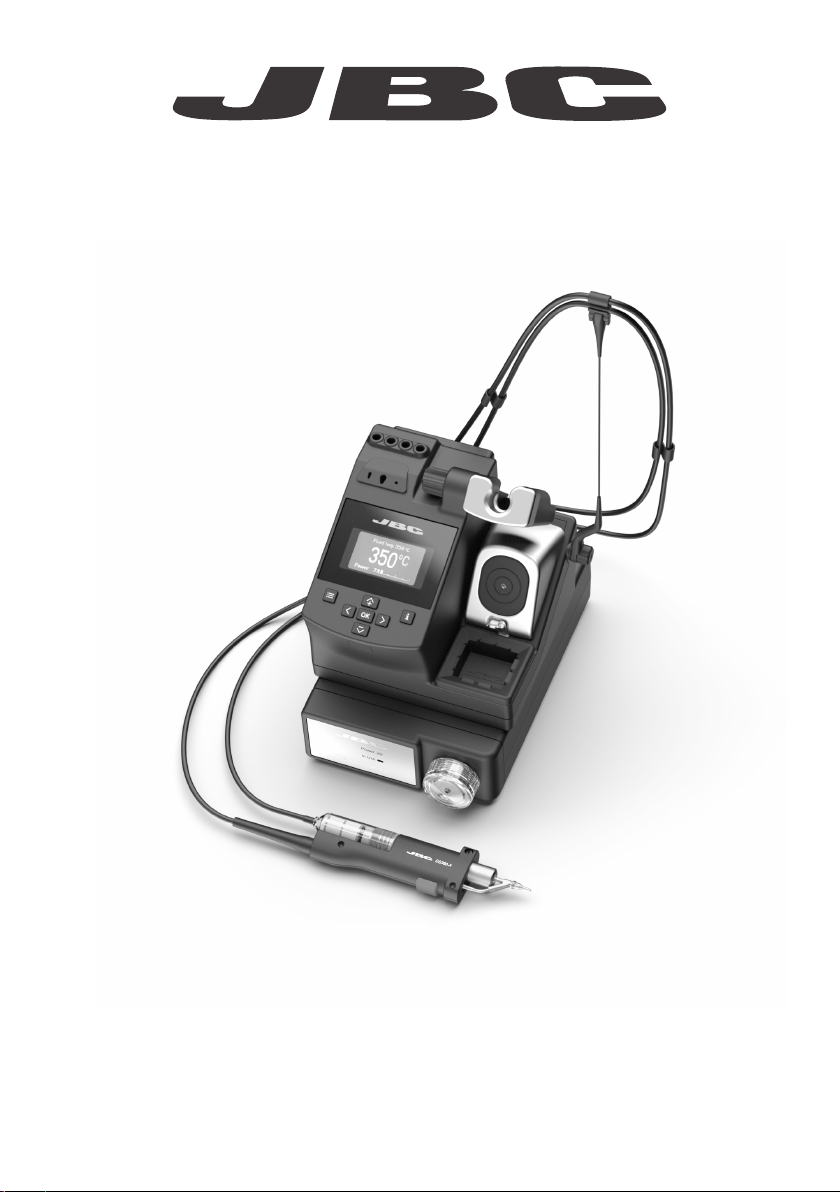
INSTRUCTION MANUAL
Compact Desoldering Station
with Electric Pump
Ref. CS-F
Page 2
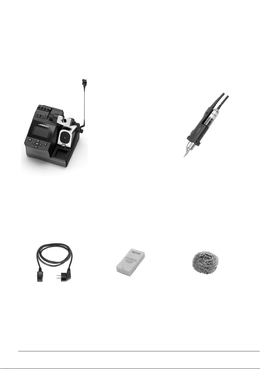
Packing List
The following items are included:
CSV Control Unit ......... 1 unit
Ref. CSV-1F (120V)
CSV-2F (230V)
CSV-9 F (100V)
Power Cord .....................1 unit
Ref. 0023715 (120V)
0023714 (230V)
0024092 (100V)
2
Sponge ........................ 1 unit
Ref. S0354
Micro Desoldering
Iron ................................... 1 unit
Ref. DS360-A
C360004 already inserted
Brass Wool ...................1 unit
Ref. C L6 210
Page 3
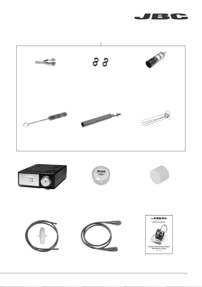
DS360-A Accessories
Ref. 0 010 259
www.jbctools.com
Tips .......................... 10 units
Ref. C360002 (x5)
C360004 (x5)
Cleaning Brush ......... 1 u ni t
Ref. 0008297
Electric Desoldering
Module ............................ 1 unit
Ref. MS-A
Union Flanges ......... 2 units
Re f. 00113 5 6
Solder Collector ..... 2 un its
Ref. 0008467
Filter Box ........................ 1 un it
Ref. 0005966
It contains 50 filters
Filter ........................... 2 units
Ref. 0008473
Cleaning Rods .............. 1 unit
Ref. 0008466
Cotton Filter ................... 1 unit
Ref. 0781046
It contains 10 filters
Suction Filter ................ 1 unit
Re f. 08 21830
Module Cable ............. 1 unit
Ref. 0010207
Manual ......................... 1 unit
Ref. 0026123
3
Page 4
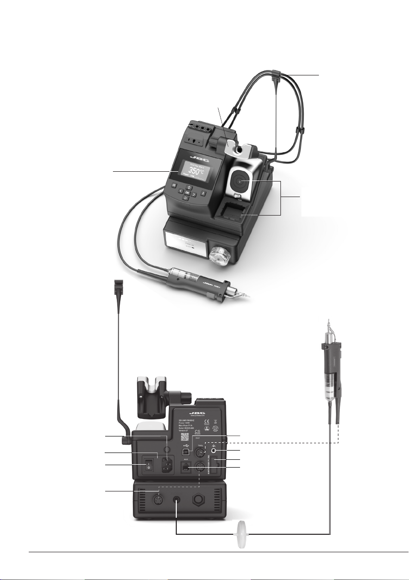
Features and Connections
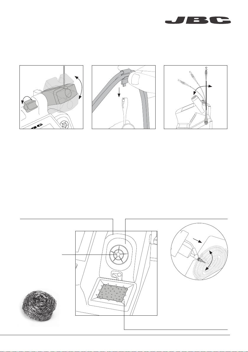
Adjustable Stand:
Intelligent Heat Management
Process
Screen
Cable Collector
Tip Cleaner Brass Wool
with Antisplash Membrane
and Wiper
4
Power Socket
Fuse
Main switch
Module Cable
Ref. 0010207
Micro
Desoldering Iron
Ref. DS360-A
USB-B Connector
Equipotential Connection
Earth Fuse
Fume Extractor Connector
Suction Filter
Re f. 08 21830
Page 5
www.jbctools.com
Adjustable Stand Cable Collector (Ref. CC1001)
Adjust the tool stand to suit
your work position.
The Cable Collector keeps the cable away from the work area
and prevents that the weight of the cable from disturbing the
operator while soldering.
Insert the cable into the clip
and then insert into the Cable
Collector. Do not leave the
cable longer than necessary
The Cable Collector is flexible.
It accompanies and adapts
to the movements during the
soldering process.
to reach the work area freely.
Tip Cleaner
Select the option to suit your needs and improve the thermal transfer of the tip.
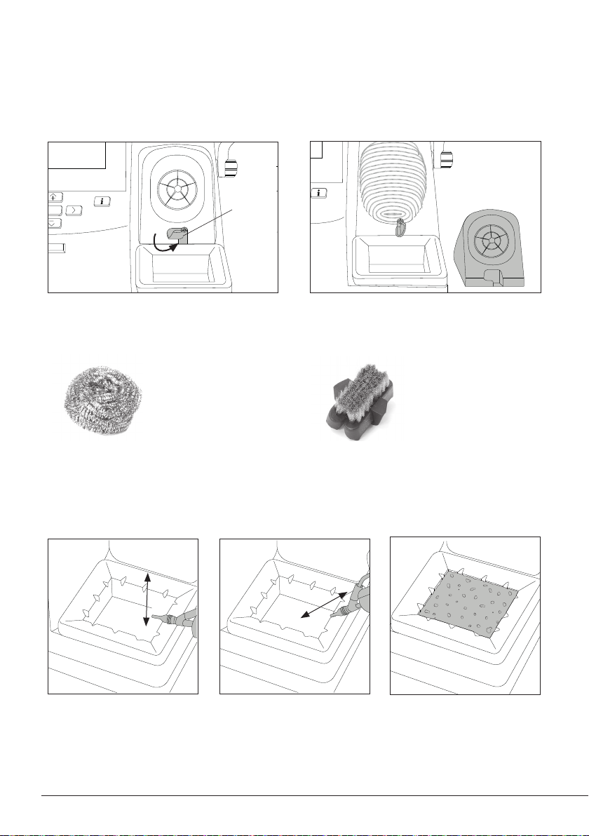
Splashguard
Ref . 0017576
It prevents splashing of solder particles
when using the brass wool.
Antisplash Membrane
Ref. 0 0175 74
Prevents splashing to maintain the work
area clean.
Brass Wool
Ref. C L6 210
Very ef fective cleaning
method. Leaves a small
layer of solder on the
tip preventing oxidation
between cleaning and
rewetting.
If the tip is very dir ty,
JBC recommends f irst
cleaning it with the
wiper to remove excess
solder.
Wiper R ef. CL0160
A temperature resistant receptacle for removing excess
solder by gently tapping or wiping.
5
Page 6
OK
Removing the Splashguard
OK
TOOL
EARTHING FUSE
AUX
USE ONLY WITH A 250 V FUSE
OK
EARTHING FUSE
AUX
USE ONLY WITH A 250 V FUSE
1. Unlock the splashguard. 2. Lift off.
More cleaning options (not supplied):
Inox Wool
Ref. CL6205
Stronger cleaning
method than brass
wool.
Wiper
Ref. CL0160
Lock
Metal Brush
Ref. CL6220
When used carefully,
it provides a more
thorough cleaning.
Sponge
Ref. S0354
Tapping:
Tap gently to remove excess
solder.
Wiping:
Use the slots to remove
remaining particles.
The softest cleaning method.
Keep the sponge damp with
distilled water when working
to avoid tip wear.
6
Page 7
A
B
C360-001
C360-007
C360-002
C360-004
www.jbctools.com
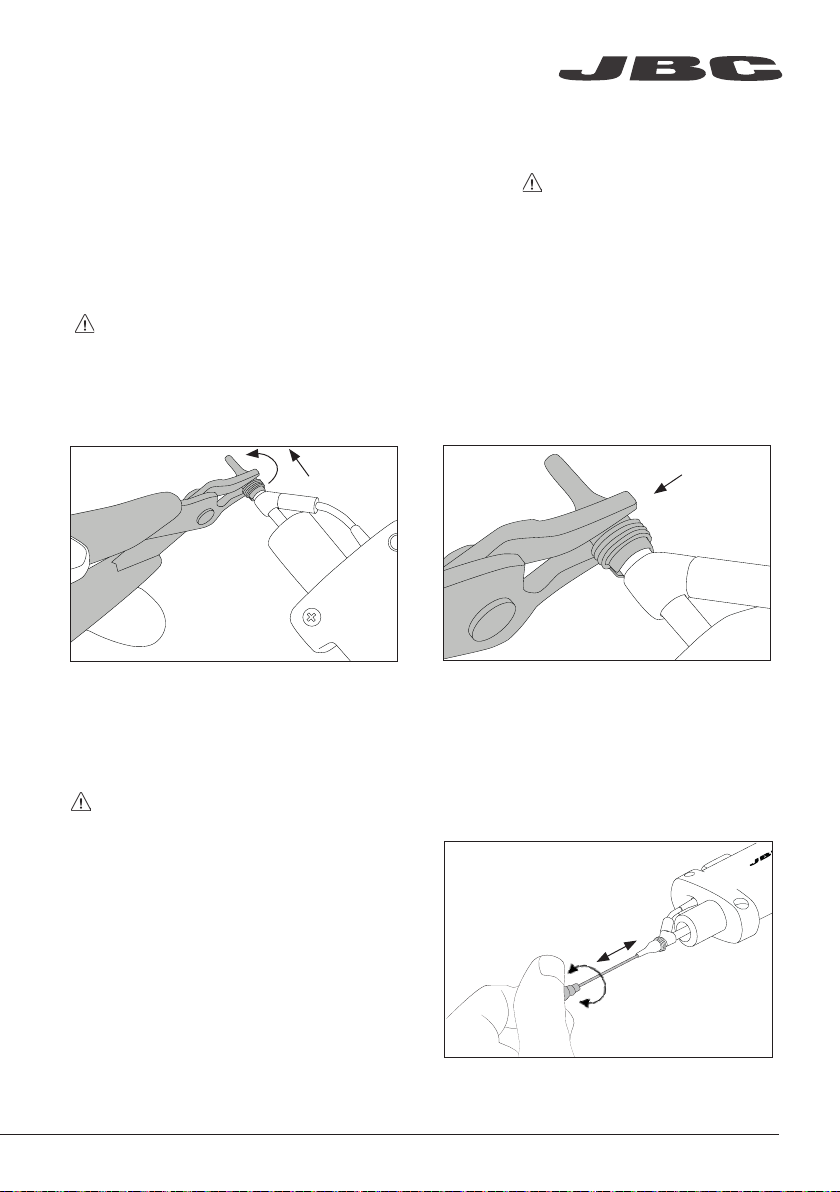
Tips Care
To prevent tip oxidation cover tip with solder tin when not in use. Note: Do not press the vacuum
pump button while tinning the desoldering tip, as the fumes given of f by the flux would quickly block
the ducts and the air filter.
Changing Tips
Note: This operation should be done while the tip is hot and at a minimum temperature of
250°C, so that any tin left inside is still molten.
1. To remove the tip, use a pair of flat-nosed
pliers, twist the tip and pull.
2. To fasten the tip, do not hold it on the spring
clamp. Place the pliers directly in front of the
spring.
Cleaning Tips
The tip hole should be periodically cleaned.
Note: Let the tool cool down before performing this operation.
Choose the cleaning rod diameter
according to the tip size. Put the rod at
the tip, gently move it back and forth
while turning it slightly.
7
Page 8
$¡
%¡
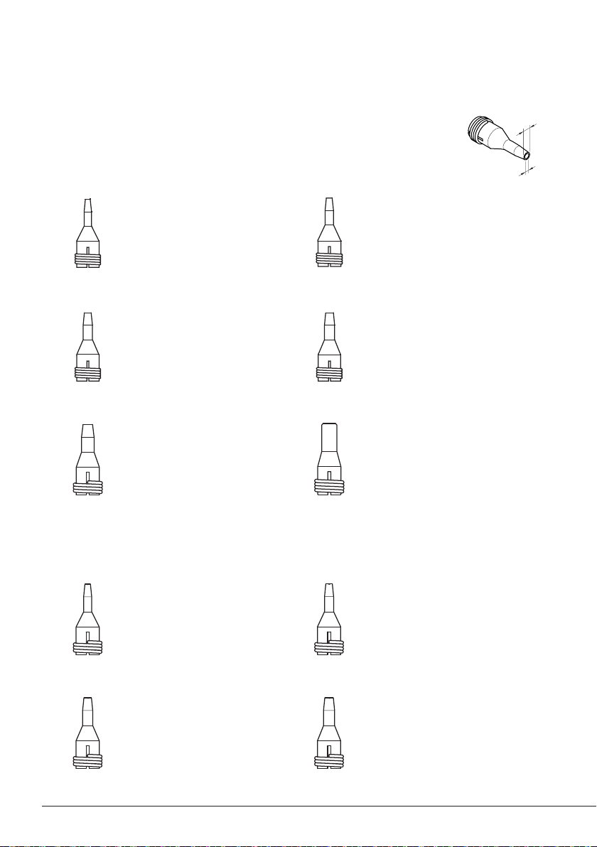
Compatible Tips
This station works with C360 tips and DS360 iron.
Find the model that best suits your needs in www.jbctools.com
Through-Hole Desoldering Tips
C360-001
ØA= 1 mm (0.04 in)
ØB= 0,6 mm (0.02 in)
Ømax. pin= 0,4 mm (0.02 in)
C360-003
ØA= 1,4 mm (0.06 in)
ØB= 1 mm (0.04 in)
Ømax. pin= 0,8 mm (0.03 in)
C360-007
ØA= 1,9 mm (0.08 in)
ØB= 1,4 mm (0.06 in)
Ømax. pin= 1,2 mm (0.05 in)
Pad Cleaning Tips
C360-011
C360-002
ØA= 1,2 mm (0.05 in)
ØB= 0,8 mm (0.03 in)
Ømax. pin= 0,6 mm (0.02 in)
C360-004
ØA= 1,6 mm (0.06 in)
ØB= 1,2 mm (0.05 in)
Ømax. pin= 1 mm (0.04 in)
C360-006
ØA= 3 mm (0.12 in)
ØB= 1,5 mm (0.06 in)
Ømax. pin= 1,3 mm (0.05 in)
C360-012
ØA= 1 mm (0.04 in)
ØB= 0,6 mm (0.02 in)
C360-013
ØA= 1,4 mm (0.06 in)
ØB= 1 mm (0.04 in)
ØA= 1,3 mm (0.05 in)
ØB= 0,8 mm (0.03 in)
C360-014
ØA= 1,6 mm (0.06 in)
ØB= 1,2 mm (0.05 in)
8
Page 9
www.jbctools.com
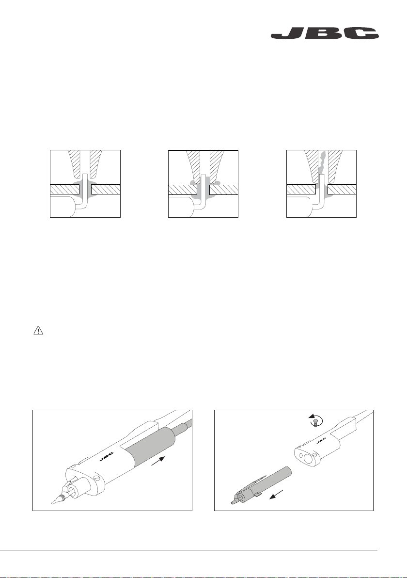
Desoldering Process
When desoldering, use a tip with a diameter larger than the pad being desoldered. This will achieve
maximum suction and thermal efficiency.
1. Apply the tip so that it fits
over the component terminal.
The vacuum pump will continue to run for a few seconds. This makes sure that the vacuum
circuit is completely empty. If there are any solder remains left on a terminal, just resolder it
with fresh solder and repeat the desoldering operation.
2. When the solder liquefies,
gently rotate the tip so that the
terminal can be lifted off.
3. Then press the vacuum
pump button long enough to
suck up the solder.
Desoldering Iron Maintenance
Note: For the following operations, turn off the station or disconnect the tool and wait until the
tool temperature drops to room temperature.
Changing Heating Element
1. Remove the filter before changing the
heating element.
2. Remove the fixing screw and take out the
heating element.
9
Page 10

A
B
C360-007
C360-004
A
B
C360-001
C360-003
C360-007
C360-002
C360-004
C360-006
A
B
C360-007
C360-004
3. Insert the new heating element into the tool. 4. Tighten the fixing screw and insert the filter.
Changing Iron Filter
1. Remove the tube from the filter. 2. Remove the filter form the tool.
3. Insert a new filter (ref. 0008473) into the tool
and mount the tube onto the filter.
10
Page 11

A
B
C360-001
C360-003
C360-007
C360-002
C360-004
C360-006
A
B
C360-001
C360-007
C360-002
C360-004
C360-006
www.jbctools.com
Cleaning Solder Collector
Note: For this operations, turn off the station or disconnect the tool and wait until the tool
temperature drops to room temperature.
1. Remove the filter before cleaning the solder
collector.
3. Use the cleaning brush (ref. 0008297) to
clean the solder collector inside or replace it
for a new one.
2. Take out the solder collector with the metal
solder retention.
4. Insert the solder collector with the metal
solder retention into the heating element.
5. Mount the filter onto the tool.
11
Page 12

Electric Desoldering Module
Note: Before carrying out maintenance, always unplug the equipment.
If there is loss of suction, check that there is no obstruction in the tool (tip, heating element, tool
filter), tube or suction filters.
Changing Pump Filters
Periodically check the filters and replace them if they are yellowish.
Note: Do not use sharp pointed objects to open the suction filter.
Suction Filter
Ref. 0821830
Cotton Filters
Ref. 0781046
O Ring
Ref. 0007717
12
Filter Cover
Ref. 0004710
Spare Filters
Ref. 0005966
Page 13

OK
OK
www.jbctools.com
Operation
The JBC Most Efficient Soldering System
This revolutionar y technology is able to recover tip temperature extremely quickly.
This allows the user to work at a lower temperature.
As a result, tip life increases up to 5.
1. Wo rk 2. Sleep 3. Hibernation
Long time in
the stand
When the tool is lifted from the
stand the tip will heat up to the
selected temperature.
Selected temp
350
Power 5%Power 5%
· Change temperature
(from 90 to 450ºC)
Steps ± 5
Steps ± 50
Through menu settings:
· Select temperature levels
· Fix one temperature
350 350 ooCC
0
c
When the tool is in the stand,
the temperature falls to the
preset sleep temperature.
Sleep
0
c
350
Sleep temp 150Sleep temp 150ooCC
Through menu settings:
· Change Sleep temperature
· Set Sleep delay
(from 0 to 9 min or no Sleep)
After longer periods of
inactivity, the power is cut off
and the tool cools down to
room temperature.
Hibernation
0
c
350
Tool in the stand, no heat
Through menu settings:
· Change Hibernation delay
(from 0 to 35 min)
13
Page 14
Main menu
210
Back
Back
Total Counters
Tool settings
Station settings
350
o
C
Power 5%
350
o
C
270
350
400
-10
210
Back
EARTH
FUSE
Control Process
Station Settings
Minimum Temperature
Set the minimum temperature
to work with.
Min. temp. by default is 200ºC
(392ºF ). This is considered to
be a proper starting point for
leaded applications.
Maximum Temperature
Set the maximum
temperature to work with.
Max. temp by default is 400°C
(750°F). This is considered
high enough to work with
most lead-free applications.
Temperature Unit
Celsius (ºC) or Fahrenheit (ºF)
Recommendations Parameter Description
N/a
Warnings
The station temperature
range is 90-450ºC
(190-840ºF). Change the
temperature limits when
working with less common
applications such as low / high
melting point soldering (HMP)
or plastics (e. g. riveting).
In most cases,
working with temperatures
over 400°C (750°F) can
damage the PCB and its
components. Even in short
time periods of tip contact
with the soldering joint, the
flux may not work properly
and could seriously reduce
tip life. If the solder joint
requires more power
(e.g. multilayered or high
dissipation boards), JBC
strongly recommends using
other aids like preheaters.
Be careful when using these parameters as they may reduce the tip life if not used properly.
Please follow the recommended guidelines:
Parameters
Metronome
This activates a beep sound.
Frequencies vary from 1 to 50
seconds.
Change Pin
Change the default security
PIN number (0105).
The PIN must be entered every
time a parameter is changed.
Useful for setting a work rate
in repetitive jobs. The beep
lets you know the length of
time the tip must be in contact
with the soldering joint.
N/a
N/a
N/a
N/a
Pin
Enable/disable pin prompt. N/aN/a
QST
Enable/disable QST. N/aN/a
Beep
Enable/disable the beep
sound of the keypad.
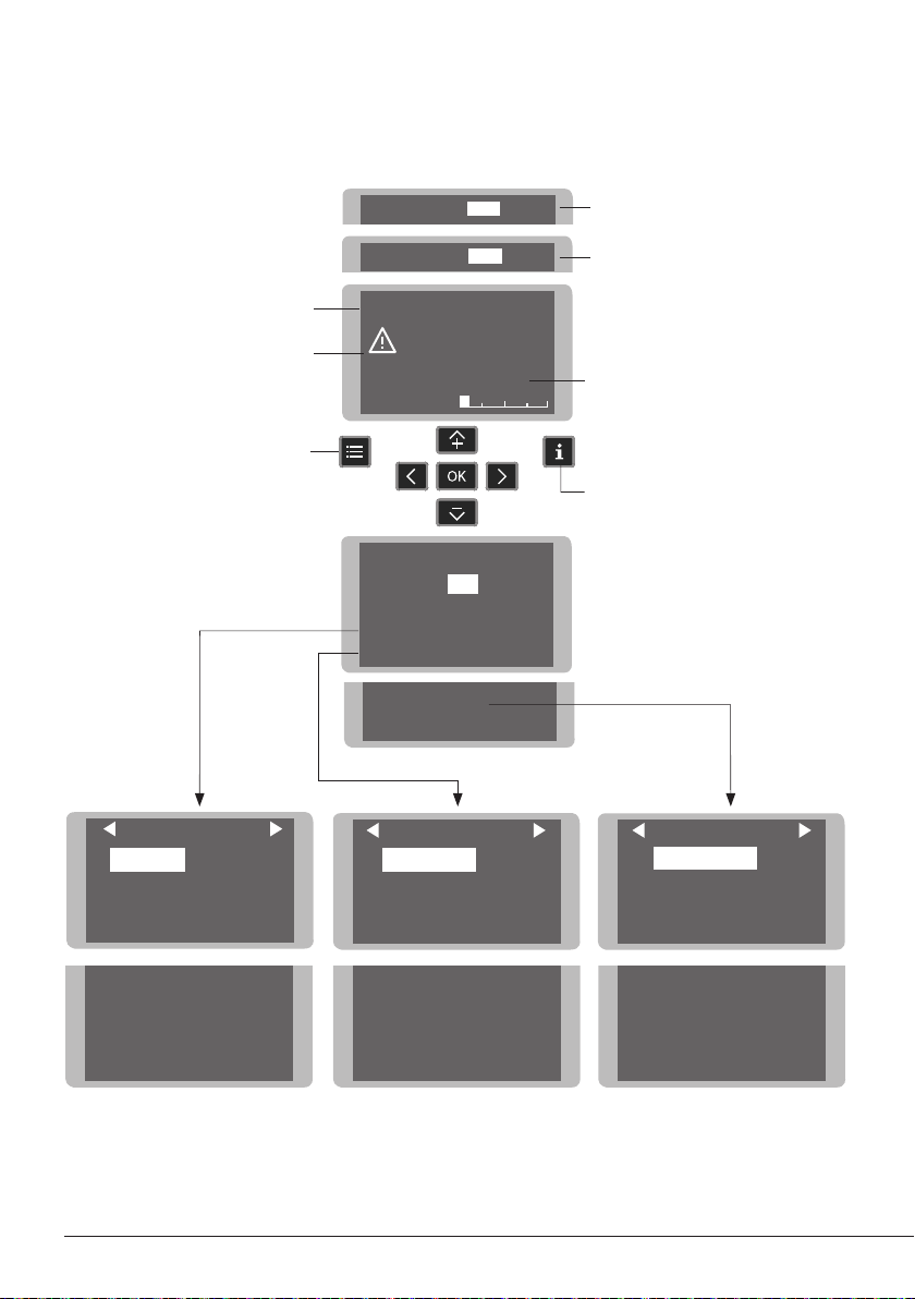
Work Screen
The work screen provides
useful information of tool
status in real time.
Levels ºC
Selected temp.
Earth Fuse warning is
shown when fuse is
blown. Replace the fuse.
Menu
EARTH
FUSE
Power 5%
Menu Screen
Default PIN: 0105
Exit
1 Reset settings
2
3
4 Counters
5
Fixed temp.
270
350
350
350
0
350
Main menu
Station settings
Tool settings
Program version
o
400
c
-10
C
o
C
Displays a specific fixed temp.
Shown when you have selected
temp. levels. T he values must be
adjusted for the task.
“Temp. Adjust ” parameter.
It provides a more precise
adjustment between the selected
temp and the actual one.
Help Information
Station settings
1 Temp unit
2
Maximum temp 4000C
3
Minimum temp 2000C
4
Metronome ----
Celsius
Tool settings
1
Fix one temp -----
2
Temp levels set OFF
3
Sleep delay 0 min
Tool
210
5 Beep ON
6 QST ON
7
PIN ON
8
Change PIN
Back
4
Sleep temp 1500C
5
Hibernation delay 10 min
6
Temp adjust + O OC
Back
Tool
210
Troubleshooting
Station troubleshooting available on the product page at www.jbctools.com
14
Total Counters
1
Plugged hours 0
2
Working hours 0
3
Sleep hours 0
4 Hi
bernation hours 0
5
No tool hours 0
6 Sleep cycles
0
Back
Page 15

www.jbctools.com
Parameters
Be careful when using these parameters as they may reduce the tip life if not used properly.
Please follow the recommended guidelines:
Station Settings
Temperature Unit
Celsius (ºC) or Fahrenheit (ºF)
Maximum Temperature
Set the maximum
temperature to work with.
Max. temp by default is 400°C
(750°F). This is considered
high enough to work with
most lead-free applications.
Minimum Temperature
Set the minimum temperature
to work with.
Min. temp. by default is 200ºC
(392ºF ). This is considered to
be a proper starting point for
leaded applications.
Metronome
This activates a beep sound.
Frequencies vary from 1 to 50
seconds.
Beep
Enable/disable the beep
sound of the keypad.
Recommendations Parameter Description
N/a
The station temperature
range is 90-450ºC
(190-840ºF). Change the
temperature limits when
working with less common
applications such as low / high
melting point soldering (HMP)
or plastics (e. g. riveting).
Useful for setting a work rate
in repetitive jobs. The beep
lets you know the length of
time the tip must be in contact
with the soldering joint.
N/a
Warnings
In most cases,
working with temperatures
over 400°C (750°F) can
damage the PCB and its
components. Even in short
time periods of tip contact
with the soldering joint, the
flux may not work properly
and could seriously reduce
tip life. If the solder joint
requires more power
(e.g. multilayered or high
dissipation boards), JBC
strongly recommends using
other aids like preheaters.
N/a
N/a
QST
Enable/disable QST. N/aN/a
Pin
Enable/disable pin prompt. N/aN/a
Change Pin
Change the default security
PIN number (0105).
The PIN must be entered every
time a parameter is changed.
N/a
15
Page 16

Tool Settings
Recommendations Parameter Description Warnings
Fix One Temperature
Fix a value within the
temperature range of the
station (90-450ºC/190-840ºF).
Temperature Levels Set
Similar to “Fix one temp”
parameter. In this case, the
user can set up to 3 values for
different power requirements.
Sleep Delay
Set the time that the tool
will remain at the selected
temperature when in the stand
before entering sleep mode.
The tip temperature will then
drop to the Sleep temperature.
Ideal for soldering more than
one component at a specific
temperature. The station will
reject any attempt to change
the temperature.
This allows a quick change
between 3 different temperatures. Set them according
to the allowed values for your
soldering applications.
Because our tools reach the
working temperature from the
deafult Sleep mode in only a
few seconds, this parameter is
preset to 0 min. Once the tool
is returned to the stand the
temperature will automatically
drop to the sleep temperature,
extending tip life and avoiding
oxidation. Retinning the tip
before placing the tool in the
stand will protect the tip and
extend its life.
N/a
N/a
Setting these
parameters to higher values
will unnecessarily accelerate
oxidation and shorten tip
life especially when working
with temperatures up to
450°C (840°F).
Sleep Temperature
This is the set temperature the
tip reaches when returned to
the stand.
16
The sleep temperatures are
set to achieve a balance
between preventing oxidation
and reaching the working
temperature in a few seconds.
Page 17
Tool Settings
www.jbctools.com
RecommendationsParameter Description Warnings
Hibernation Delay
Set the time the tool will
remain at Sleep temperature
before entering the Hibernation
mode. At this time, the power
supply is cut off and the tip
remains at room temperature.
Temp Adjustment
It provides a more precise
adjustment between the
selected temperature and the
actual one.
This function completely
protects the tip from oxidation
during long periods of
inactivity while the tool is in the
stand.
Retinning the tip before
placing the tool in the stand
also helps prevent oxidation
and extends the life of the tip.
Set values within ±50°C
(± 90°F) to achieve zero error.
JBC strongly recommends
the use of TID-A or TIA-A
Thermometers to obtain
precise readings.
Increasing the default
value will accelerate
oxidation and shorten the
tip life.
When the user changes
the cartridge type, the
parameter should be reset
to 0°C/F or to the value
needed for this cartridge.
E.g. If a correction of +20°C
(+36°F) is set for a thick
cartridge and then the
user changes to a thinner
one whitout resetting the
temperature adjustment, he
would be working at a higer
temperature than needed
for this thinner cartridge,
which does not need any
temperature adjustment.
17
Page 18

A
B
C360-001
C360-003
C360-007
C360-002
C360-004
C360-006
USB Connector
Download the latest software from our website to improve your soldering station.
JBC Updater
www.jbctools.com/software.html
Update the station software via USB connection:
Cable USB AB
JBC
Updater
JBC Web Manager
www.jbctools.com/manager.html
Manage and monitor as many stations as your PC can handle by using the JBC Web Manager.
You can export data to another PC.
any JBC
station
18
Cable USB AB
USB
Hub
JBC Web
Manager
Manager Settings
Change settings for a
group of JBC stations
at the same time.
Register Settings
Create graphs of the
soldering process in
real time with power
and temperature data.
Page 19
EARTHING FUSE
AUX
USE ONLY WITH A 250 V FUSE
OK
www.jbctools.com
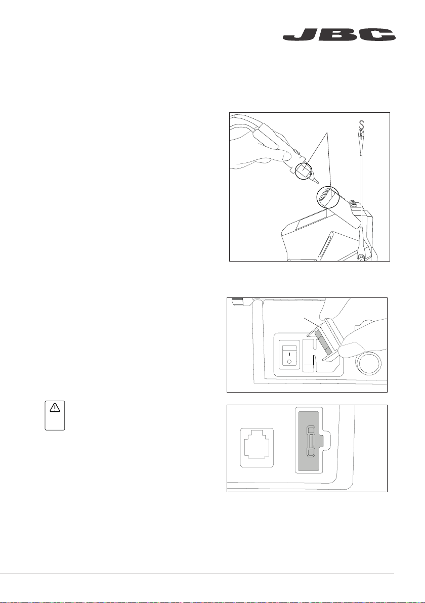
Maintenance
Before carrying out maintenance, always switch the device off and disconnect it from the mains.
Allow the equipment to cool down.
Fuse
holder
Clean
periodically
Clean
periodically
TOOL
- Clean the station screen with a glass
cleaner or a damp cloth.
- Use a damp cloth to clean the casing and
the tool. Alcohol can only be used to clean
the metal parts.
- Periodically check that the metal parts
of the tool and stand are clean so that the
station can detect the tool status.
- Maintain tip surface clean and tinned prior
to storage in order to avoid tip oxidation.
Rusty and dirty surfaces reduce heat transfer
to the solder joint.
- Periodically check all cables and tubes.
- Replace any defective or damaged pieces.
Only use original JBC spare parts.
- Replace a blown fuse as follows:
1. Pull off the fuse holder and remove the
fuse. If necessary use a tool to lever it of f.
2. Insert the new fuse into the fuse holder
and return it to the station.
EARTH
FUSE
- When this warning appears on the
AUX
main screen Earthing Fuse must be replaced
EARTHING FUSE
- Repairs should only be performed by a JBC authorized technical service.
USE ONLY WITH A 250 V FUSE
19
Page 20

Safety
It is imperative to follow safety guidelines to prevent electric
shock, injury, fire or explosion.
- Do not use the units for any purpose other than soldering or rework. Incorrect use may cause fire.
- The power cord must be plugged into approved bases. Be sure that it is properly grounded
before use. When unplugging it, hold the plug, not the wire.
- Do not work on electrically live parts.
- The tool should be placed in the stand when not in use in order to activate the sleep mode.
The soldering tip, the metal part of the tool and the stand may still be hot even when the station
is turned off. Handle with care, including when adjusting the stand position.
- Do not leave the appliance unattended when it is on.
- Do not cover the ventilation grills. Heat can cause inflamable products to ignite.
- Avoid flux coming into contact with skin or eyes to prevent irritation.
- Be careful with the fumes produced when soldering.
- Keep your workplace clean and tidy. Wear appropriate protection glasses and gloves when
working to avoid personal harm.
- Utmost care must be taken with liquid tin waste which can cause burns.
- This appliance can be used by children over the age of eight and also persons with reduced
physical, sensor y or mental capabilities or lack of experience provided that they have been given
adequate supervision or instruction concerning use of the appliance and understand the hazards
involved. Children must not play with the appliance.
- Maintenance must not be carried out by children unless supervised.
20
Page 21

Notes
www.jbctools.com
21
Page 22

Notes
22
Page 23

www.jbctools.com
Specifications
CS -1F 120V 50/60Hz. Input fuse: 2A. Output: 23.5V. Control Unit model: C SV -1F
CS-2F 230V 50/60Hz. Input fuse: 1A. Output: 23.5V. Control Unit model: CSV-2F
CS-9F 100V 50/60Hz. Input fuse: 2A. Output: 23.5V. Control Unit model: CSV-9F
- Output Peak Power CS-F: 40W
- Temperature Range: 180 - 450 °C / 360 - 840 °F
- Idle Temp. Stability (still air): ±1.5ºC / ±3ºF (Meets and exceed IPC J-STD-001)
- Temp accuracy: ±3% (using reference cartridge)
- Temp adjustment: ±50 ºC / ±90ºF Through station menu setting
- Tip to ground voltage/resistance: Meets and exceed
ANSI/ESD S20.20-2014 IPC J-STD-001F
- Earthing Fuse: F 1.25A
- Connections: USB connector station-PC
RJ12 Connector
- Ambient operating temp: 10 - 50 ºC / 50 - 122 ºF
- Control Unit Dimensions / Weight: 170 x 176 x 145 mm / 2.8 Kg
(L x W x H) 6.7 x 6.9 x 5.7 in / 6.17 lb
MS-A
- Dimensions / Weight: 145 x 55 x 225 mm / 1.2 kg
(L x W x H) 5.7 x 2.2 x 8.9 in / 2.6 lb
- Vacuum: 75% / 570 mmHg / 22.4 inHg
- Flow rate: 9 SLPM
- Total Package Dimensions / Weight: 495 x 295 x 255 mm / 5.47 kg
(L x W x H) 19.5 x 11.6 x 10 in / 12.06 lb
Complies with CE standards.
ESD protected housing.
23
Page 24

Warranty
JBC’s 2 year warranty covers this equipment against
all manufacturing defects, including the replacement
of defective parts and labour.
Warrant y does not cover product wear or misuse.
In order for the warranty to be valid, equipment must
be returned, postage paid, to the dealer where it was
purchased.
Get 1 extra year JBC warranty by registering here:
https://www.jbctools.com/productregistration/
within 3 0 days of purchase.
This product should not be thrown in the garbage.
In accordance with the European directive 2012/19/EU, electronic equipment at the end of its life must
be collected and returned to an authorized recycling facility.
www.jbctools.com
00 2 612 3 -0 12 1
 Loading...