

Page 1
www.jbctools.com
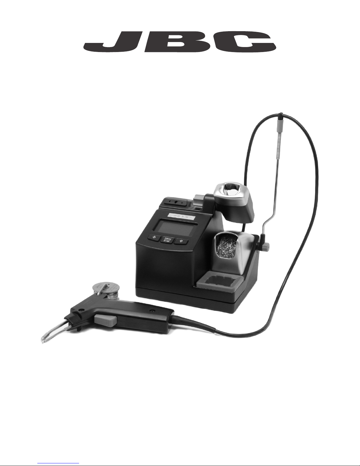
CF
SOLDER FEED STATION
Page 2
2
www. jbct ool s.co m
CF
SOLDER FEED STATION
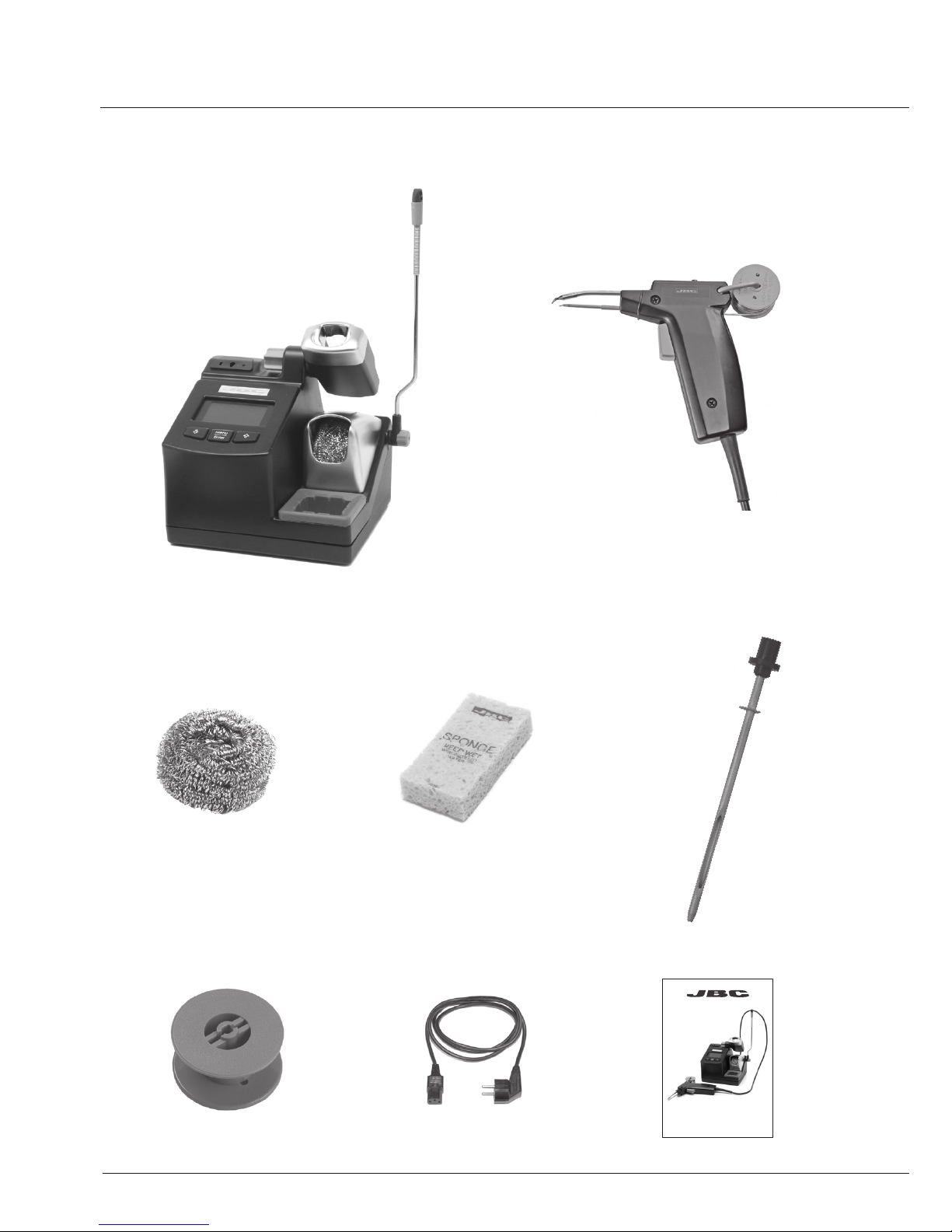
AP130-A
Solder Feed Iron
MANUAL0002801 Reel
0006559
Feeding tube
POWER CORD
CL6210 Brass Wool
CF / SOLDER FEED STATION
CF-2C / CF-1C / CF-9C
Control Unit
S0354 Sponge
Page 3

3
Main switch
Equipotential connection
Power Cord Socket
Cable collector
Tip Cleaning System
Process Control
Intelligent Heat Management
PART NAMES
INSTALLATION
AP130-A
Solder Feed Iron
USB-B connector to PC:
- Update station software
- Create graphs of the soldering process
- Manage and monitor parameters via PC
CONTROL UNIT
Page 4

4
CF / SOLDER FEED STATION
Loosen the tightening knob to adjust the position
of the cable collector.
ADJUSTABLE STAND
CABLE COLLECTOR
The tool stand is easily adjustable. Loosen the tightening knob to adjust the position.
Slide the green piece down to place the wire.
Page 5

5
Tap smoothly the cartridge on the wiper profile to
remove the excess of solder
Provides a deeper cleaning on the tip.
CL6205 Inox Wool
TAPPING WIPING
S0331 Sponge S0354 Sponge
Use the slots to wipe any posible particle sticked
on the tip
More agressive on the tip than the wool.
CL6220 Brushes
CLEANING OPTIONS
Full set of clean option: sponge, metal wool and brush
The smoothest cleaning method. The sponge has to be kept wet (not soaked) using distilled water.
Page 6

Guide tube screw
6
Place the new cartridge in the solder feed handle.
Important: It is essential to insert the cartridge
till the end for a good connection.
Use the mark as reference.
CF / SOLDER FEED STATION
CHANGING THE CARTRIDGE
Cartridge screw
Alignment
21
3
Loosen the cartridge screw to release the
cartridge.
Align the tip of the cartridge with the solder
guide tube.
Important: It is esential to tighten the cartridge
screw for the tool to function.
SOLDER FEED IRON
AP130-A Solder Feed Iron
The AP130-A offers a ‘third hand’ by feeding soldering wire of diameters 0.8 to 1 mm.
Specifically suitable for high-volume soldering jobs, and whenever an extra hand is needed.
SN5450
Solder Reels for AP130-A
Supplied with lead
free solder reel - 99%
Sn / 0,3% Ag / 0,7%
Cu - with 50g solder.
Consult our wide range of cartridges with more than 300 references in www.jbctools.com.
For special cartridges contact with our distributor.
Uses C130 cartridge range.
Page 7

ACCESSORIES (not included)
Press the empty reel to remove it and replace it
with a new one.
7
REPLACING THE REEL
Always use 0.8 to 1.0 mm diameter solder wire.
Press
1
2
3
F1204
Fume Extractor
BE-SA
Solder reel stand
For production-line purposes we
recommend using our BE-SA holder which
allows for solder reels of sizes up to 2.5 Kg
to be used.
Simply wrap a couple of turns of the solder
wire around an empty reel as shown.
Before fitting a new reel, pull out the solder
remaining inside the solder direction tube.
Insert the solder into its hole checking that the
wire becomes straight. Pull the trigger
intermittently until the solder feed system works
by itself.
Page 8

Count er s
Tool se tt in gs
Exit
1 Reset settings
2
Station settings
3
Tool settings
1
Plugged hours 0
2
Working hours 0
3
Sleep hours 0
1
Fix one temp -----
2
Temp levels set OFF
3
Sleep delay 0 min
4 Counters
5
Program version
4
Hibernation hours 0
5
No tool hours 0
6 Sleep cycles
0
4
Sleep temp 1800C
5
Hibernation delay 30 min
6
Temp adjust + O OC
Tool AP
Tool AP
Back
Back
Stati on set ti ng s
1 Temp unit
Celsius
2
Maximum temp 4000C
3
Minimum temp 2000C
4
Help text OFF
5 Beep ON
6 Power limit 130W
7
Change PIN
Back
Main me nu
0
c
Selected temp.
350 oC
P ow e r 1 0%
350
8
CONTROL SCREEN
SETTINGS MENU
Tip temperature
Decrease &
move down
Increase &
move up
Access Menu &
Confirm Selection
% Instant power supplied
to the tool
Original PIN: 0105
CF / SOLDER FEED STATION
Page 9

Expected life
(hours)*
Sleep
Temp
Working
Temp
Temp (ºC)
700
600
500
400
300
200
200 225 250 275 300 325 350 375 400 425 450
100
0
9
JBC stations intelligently manage the tool temperature and it helps to extend the tip life:
Heat management increase tip life which reduces cost of ownership.
HEAT MANAGEMENT
Work mode: Lift tool from the stand and the tool tip heats up to the selected temperature.
Sleep mode: When the tool is in the stand, the temperature reduces (preset sleep temperature is
180ºC / 360ºF).
Hibernation mode: After longer periods of inactivity (pre-set to 30 minutes), the power is cut off and
the tool cools down to room temperature.
Page 10

10
MAINTENANCE
Prior to maintenance or storage should
disconnect the equipment from the power supply
and let it cool down.
- Use a damp cloth to clean the case and the
tool. Alcohol can be used only to clean the
metal parts.
- Check periodically that the metal parts of the
tool/stand are clean in order to have a good
detection when the tool is in the stand.
- Clean the station’s screen with a glass cleaner
Remove the fuse by pulling the black cap. Help
yourself with a lever tool if necessary.
Place the new fuse into the holder by pushing
and enter it again into the station.
Clean periodically
or a damp cloth.
- Maintain tip surface clean and tinned prior to storage in order to avoid tip oxidation.
Rusty and dirty surfaces reduce heat transfer to the solder joint.
- Periodically check all cables and tubes connected.
- Replace any defective or damaged handpiece or tool.
- Replace the fuse if it is blown according to the following guidelines:
REPAIR
- Repairs should be performed only by a specialist. Otherwise JBC can not rule out the risk of accident.
- JBC offers you a professional after-sales service for your equipment.
CF / SOLDER FEED STATION
Page 11

11
SAFETY
- Keep children and non-trained personnel away from the equipment.
- The mains cable must be plugged into approved bases.
- The tool should be placed in the stand when not in use. This way the sleep mode will be activated.
- The soldering tip and the metal part of the tool may still be hot even when the station is turned off.
Handle with care.
- The stand can also be hot as well. To adjust the angle, turn the station off and wait until the cartridge
cools down.
- Be careful with the remains of liquid tin. In contact with skin, it can cause burns.
- Use a “non residue” classified flux and avoid contact with skin or eyes to prevent irritation.
- Do not work on electrically live parts. Antistatic handle of soldering irons is electrically conductive.
- Be careful with the smoke produced when soldering.
- Wear appropriate protection glasses and gloves when working to avoid any damage.
CAUTION
- Incorrect use of tool may cause fire.
- Be careful when using the tool in areas where inflamable products are stored.
- Heat can cause inflamable products to ignite even when not in sight.
It is imperative to meet the following safety guidelines to protect health and prevent
electric shock, injury, fire or explosions.
Page 12

0013991-1113
TECHNICAL SPECIFICATIONS
- Temperature selection from 90°C (190°F) to 450°C (840°F) (±5%).
- Output Peak Power: 130W.
- Safety transformer, mains separator and double isolation.
- CF-2C 230V 50/60Hz. Input fuse: 1A. Output: 23,5V.
- CF-1C 120V 50/60Hz. Input fuse: 2A. Output: 23,5V.
- CF-9C 100V 50/60Hz. Input fuse: 2A. Output: 23,5V.
- Total unit weight: 2,8 Kg.
- Complies with CE standards on electrical safety, electromagnetic compatibility
and ESD protected housing “skin effect”.
- RoHS compliant.
- Equipotential connector and the tool tip are connected to the station’s mains grounding
for ESD protection.
This product should not be
thrown in the garbage.
WARRANTY
JBC’s 2 year warranty covers this equipment against all
manufacturing defects, including the replacement of defective
parts and labour.
Warranty does not cover product wear due to use or mis-use.
In order for the warranty to be valid, equipment must be returned,
postage paid, to the dealer where it was purchased enclosing
this form duly filled in.
www.jbctools.com
SERIAL Nº
DEALER’S STAMP
DATE OF PURCHASE
 Loading...