

Page 1

www.jbctools.com
Precision Soldering Station
Ref. CD-SC
Page 2
2
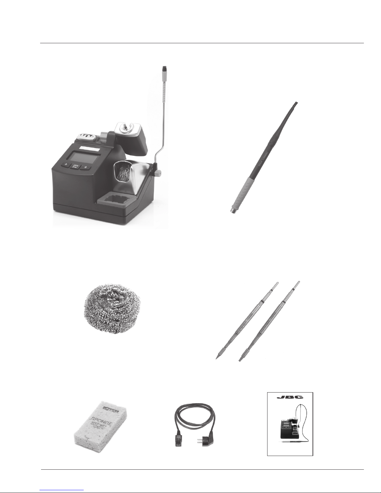
T210-A
Precision Handpiece
C210001
C210008
Cartridges
MANUAL
POWER CORD
www. jbct ool s.co m
S0354 Sponge
CL6210 Brass Wool
CD-2C / CD-1C / CD-9C
Control Unit
CD-SC / PRECISION SOLDERING STATION
Precision Soldering Station
Ref. CD-SC
Page 3
3
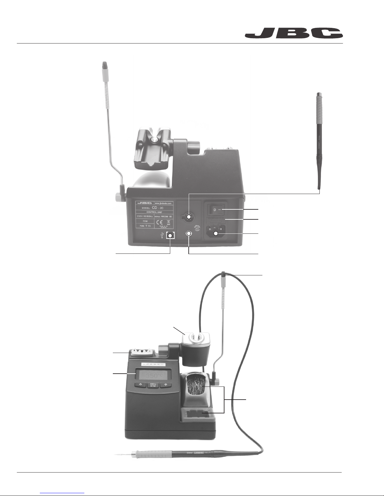
Power Cord Socket
Main switch
Fuse
Cable collector
Quick Tip Changer
Tip Cleaning System
Process Control
Intelligent Heat Management
Equipotential connection
CONTROL UNIT
T210-A
Precision
Handpiece
USB-B connector to PC:
- Update station software
- Create graphs of the soldering process
- Manage and monitor parameters via PC
INSTALLATION
PART NAMES
Page 4

4
Loosen the tightening knob to adjust the
position of the cable collector.
ADJUSTABLE STAND
CABLE COLLECTOR
The tool stand is easily adjustable. Loosen the tightening knob to adjust the position.
Slide the green piece down to place the wire.
CD-SC / PRECISION SOLDERING STATION
Page 5

5
Tap smoothly the cartridge on the wiper profile to
remove the excess of solder
Provides a deeper cleaning on the tip.
CL6205 Inox Wool
TAPPING WIPING
Full set of clean option: sponge, metal wool and brush
S0331 Sponge S0354 Sponge
Use the slots to wipe any posible particle sticked
on the tip
More agressive on the tip than the wool.
CL6220 Brushes
The smoothest cleaning method. The sponge has to be kept wet (not soaked) using distilled water.
CLEANING OPTIONS
Page 6

6
Alignment
B
C
A
Place the handpiece on top of the new
cartridge, press it slightly down and remove
the handpiece from the extractor.
Place the handpiece in the extractor and
remove the cartridge.
Press the cartridge into the opening A, B or C:
A. For straight C210 cartridges.
B. For curved C210 cartridges.
C. For C245 cartridges.
QUICK TIP CHANGER
Important
It is essential to insert the cartridge till the
end for a good connection. Use the mark as
reference.
CD-SC / PRECISION SOLDERING STATION
Page 7

7
T210-A Precision Handpiece
These handpieces are perfect For precision applications with medium power requirements.
Use C210 cartridge range
HANDPIECE
CONNECTABLE HANDPIECES
T245-A* Handpiece
For general soldering purposes with high power requirements.
T245-PA* Blue Handpiece
Used for leaded jobs
T470-A* Comfort Handpiece with screw
It incorporates a screw for securing the cartridges.
T470-SA* Long Handpiece (3m cable)
T470-FA* Comfort Handpiece
It incorporates a foamed grip of insulating material which makes you feel
more comfortable when working
T470-MA* Long Comfort Handpiece
(3m cable)
T210-PA Precision Blue Handpiece
The blue grip allows the user to differentiate the tool for leaded jobs from the lead-free ones.
Use C210 cartridge range
*These handpieces only works with C245 cartridge range for this station.
F3450 Fume Extractor (not included)
Easily clips onto the handpiece and can be quickly removed for easy
maintenance.
ACCESSORIES
Page 8

0
c
Selected temp.
350 oC
P ow e r 1 0%
350
Main me nu
Count er s
Tool se tt in gs
Exit
1 Reset settings
2
Station settings
3
Tool settings
1
Plugged hours 0
2
Working hours 0
3
Sleep hours 0
1
Fix one temp -----
2
Temp levels set OFF
3
Sleep delay 0 min
4 Counters
5
Program version
4
Hibernation hours 0
5
No tool hours 0
6 Sleep cycles
0
4
Sleep temp 1800C
5
Hibernation delay 30 min
6
Temp adjust + O OC
Tool 210
Tool 210
Back
Back
Stati on set ti ng s
1 Temp unit
Celsius
2
Maximum temp 4000C
3
Minimum temp 2000C
4
Help text OFF
5 Beep ON
6
Change PIN
Back
8
CONTROL SCREEN
SETTINGS MENU
Tip temperature
Decrease &
move down
Increase &
move up
Access Menu &
Confirm Selection
% Instant power supplied
to the tool
Original PIN: 0105
CD-SC / PRECISION SOLDERING STATION
Page 9

Expected life
(hours)*
Sleep
Temp
Working
Temp
Temp (ºC)
700
600
500
400
300
200
200 225 250 275 300 325 350 375 400 425 450
100
0
9
JBC stations intelligently manage the tool temperature and it helps to extend the tip life:
Heat management increase tip life which reduces cost of ownership.
HEAT MANAGEMENT
Work mode: Lift tool from the stand and the tool tip heats up to the selected temperature.
Sleep mode: When the tool is in the stand, the temperature reduces (preset sleep temperature is
180ºC / 360ºF).
Hibernation mode: After longer periods of inactivity (pre-set to 30 minutes), the power is cut off and
the tool cools down to room temperature.
Page 10

10
CD-SC / PRECISION SOLDERING STATION
MAINTENANCE
Before carrying out maintenance or storage, always allow the equipment to cool.
- Replace any defective or damaged pieces. Use original JBC spare parts only.
- Repairs should only be performed by a JBC authorized technical service.
- Maintenance shall not be carried out by children unless supervised.
Remove the fuse by pulling the black cap. Help
yourself with a lever tool if necessary.
Place the new fuse into the holder by pushing
and enter it again into the station.
Clean periodically
- Clean the station’s screen with a glass cleaner or
a damp cloth.
- Maintain tip surface clean and tinned prior to storage in order to avoid tip oxidation.
Rusty and dirty surfaces reduce heat transfer to the solder joint.
- Periodically check all cables and tubes connected.
- Replace the fuse if it is blown according to the following guidelines:
- Use a damp cloth to clean the case and the
tool. Alcohol can be used only to clean the
metal parts.
- Check periodically that the metal parts of the
tool/stand are clean in order to have a good
detection when the tool is in the stand.
Page 11

11
It is imperative to follow safety guidelines to prevent electric
shock, injury, fire or explosion.
- Do not use the units for any purpose other than soldering or rework. Incorrect use may cause
fire.
- The power cord must be plugged into approved bases. Be sure that it is properly grounded
before use. When removing it, hold the plug, not the wire.
- Do not work on electrically live parts. Antistatic handle of soldering irons is electrically
conductive.
- The tool should be placed in the stand when not in use in order to activate the sleep mode. The
soldering tip, the metal part of the tool and the stand may still be hot even when the station is
turned off. Handle with care, including when adjusting the stand position.
- Do not leave the appliance unattended when it is on.
- Do not cover the ventilation grills. Heat can cause inflamable products to ignite even when out
of sight.
- Use a “non residue” classified flux and avoid contact with skin or eyes to prevent irritation.
- Be careful with the fumes produced when soldering.
- Keep your workplace clean and tidy. Wear appropriate protection glasses and gloves when
working to avoid personal harm.
- Utmost care must be taken with liquid tin waste which can cause burns.
- This appliance can be used by children over the age of eight and also persons with reduced
physical, sensory or mental capabilities or lack of experience provided that they have been given
adequate supervision or instruction concerning use of the appliance and understand the hazards
involved. Children must not play with the appliance. Maintenance shall not be carried out by
children unless supervised.
SAFETY
Page 12

www.jbctools.com
0013839-0414
TECHNICAL SPECIFICATIONS
- Total unit weight: 2,6 Kg.
- Size: 150 x 175 x 145 mm
- Temperature selection from 90°C (190°F) to 450°C (840°F) (±5%).
- Output Peak Power CD-SC: 40W.
- Safety transformer, mains separator and double isolation.
- CD-2C 230V 50/60Hz. Input fuse: 1A. Output: 23,5V.
- CD-1C 120V 50/60Hz. Input fuse: 2A. Output: 23,5V.
- CD-9C 100V 50/60Hz. Input fuse: 2A. Output: 23,5V.
- Input Fuse 1A (230V), 2A (120V and 100V)
- Tip to ground resistance <2 ohms
- Tip to ground voltage <2mV RMS
- Ambient operating temp: 10-40 ºC / 50-104 ºF
- USB interface station-PC
- Complies with CE standards
- ESD protected housing “skin effect”
Warranty
JBC’s 2 year warranty covers this equipment
against all manufacturing defects, including the
replacement of defective parts and labour.
Warranty does not cover product wear due to use
or mis-use.
In order for the warranty to be valid, equipment
must be returned, postage paid, to the dealer
where it was purchased.
This product should not be thrown in the garbage.
In accordance with the European directive 2002/96/EC, electronic equipment at the end of their life
must be collected and returned to an authorized recycling facility.
 Loading...